EP0304542A2 - Dispositif de fermeture assisté pour porte de véhicule automobile - Google Patents
Dispositif de fermeture assisté pour porte de véhicule automobile Download PDFInfo
- Publication number
- EP0304542A2 EP0304542A2 EP88106375A EP88106375A EP0304542A2 EP 0304542 A2 EP0304542 A2 EP 0304542A2 EP 88106375 A EP88106375 A EP 88106375A EP 88106375 A EP88106375 A EP 88106375A EP 0304542 A2 EP0304542 A2 EP 0304542A2
- Authority
- EP
- European Patent Office
- Prior art keywords
- locking
- pressure
- piston
- aid according
- door
- Prior art date
- Legal status (The legal status is an assumption and is not a legal conclusion. Google has not performed a legal analysis and makes no representation as to the accuracy of the status listed.)
- Granted
Links
Images

Classifications
-
- E—FIXED CONSTRUCTIONS
- E05—LOCKS; KEYS; WINDOW OR DOOR FITTINGS; SAFES
- E05B—LOCKS; ACCESSORIES THEREFOR; HANDCUFFS
- E05B81/00—Power-actuated vehicle locks
- E05B81/12—Power-actuated vehicle locks characterised by the function or purpose of the powered actuators
- E05B81/20—Power-actuated vehicle locks characterised by the function or purpose of the powered actuators for assisting final closing or for initiating opening
-
- E—FIXED CONSTRUCTIONS
- E05—LOCKS; KEYS; WINDOW OR DOOR FITTINGS; SAFES
- E05B—LOCKS; ACCESSORIES THEREFOR; HANDCUFFS
- E05B81/00—Power-actuated vehicle locks
- E05B81/52—Pneumatic or hydraulic circuits
-
- E—FIXED CONSTRUCTIONS
- E05—LOCKS; KEYS; WINDOW OR DOOR FITTINGS; SAFES
- E05B—LOCKS; ACCESSORIES THEREFOR; HANDCUFFS
- E05B81/00—Power-actuated vehicle locks
- E05B81/54—Electrical circuits
- E05B81/64—Monitoring or sensing, e.g. by using switches or sensors
Definitions
- the invention relates to a closing aid for a vehicle door with a latch arranged on the door or door frame, of which a closing element arranged on the door frame or door can be gripped behind in a pre-latching position of the door and the door can be moved into its closing latching position, with a pneumatic or hydraulic pressurizable piston-cylinder unit, by means of whose piston the latch can be moved from the pre-latching position into the closing latching position via active connecting elements and which can be pressurized or relieved of pressure by a control unit, as well as with a pre-latching detection for recognizing the latching position or the neutral position of the latch, from which one of the positions the trap dependent signal of the control unit can be fed.
- the object of the invention is therefore to provide a locking aid according to the preamble, which has an increased service life despite the lightweight construction.
- a lock-dependent detection of the position of the trap signal of the control unit can be fed by a locking detent detection for detecting the locking locking position or non-locking locking position of the trap, with changing the position of the trap from the neutral position to the pre-locking position and simultaneous
- the piston-cylinder unit can be actuated to be pressurizable in the locking detent position, and upon changing the position of the latch from the non-locking detent position to the locking detent position, pressurization of the piston-cylinder unit can be canceled.
- the application of the locking aid only during the effective closing movement leads to a gentle operation and thus a long service life of the locking aid.
- the latch is a rotary latch that can be rotated about an axis.
- the latch can be locked in its locking position by a manually operated locking pawl, the locking pawl can be moved between a locking position and a release position, the locking or Detachable position can be recognized and a signal dependent on the position of the pawl can be fed to the control unit, wherein pressurization of the piston-cylinder unit can be broken off in the released position of the pawl.
- pre-detent detection and / or locking detent detection and / or locking detection are cam-operated switches, the switches of the pre-detent detection and / or the locking detent detection being actuable by cams which are firmly connected to the latch and the switch of the locking detection can be actuated by a cam which is firmly connected to the pawl or a drive component of the pawl.
- Pressurizing pressure can be detected by a pressure sensor and a corresponding pressure signal can be fed to the control unit, so the closing drive can take place with a controlled maximum force and overloading of the components can be avoided.
- the piston of the piston-cylinder unit can be decoupled from the latch in the opening movement direction, the piston-cylinder unit can also be moved in the opening direction when the latch is locked in the closed latching position. It is therefore easy to open the door quickly in an emergency.
- the piston of the piston-cylinder unit can be relieved of pressure after completion of the closing process or, preferably, can even be moved into the pre-locking or neutral position by applying negative pressure.
- a closing process without great effort and thus gentle on the component, as well as a flawless closing of the door is achieved in that a Door frame arranged door seal is designed as a hollow tube profile, the inner chamber of which can be pressurized with a certain target pressure after completion of a closing process of the door. By pressurizing the door seal, it fits perfectly against the door that is attached to it.
- the pressure acting on the door seal can be detected by a pressure sensor and a corresponding pressure signal can be fed to the control unit, and the pressure on the door seal can be relieved of pressure after the setpoint pressure has been reached.
- the target pressure or the pressure lower than the target pressure or an operating pressure higher than the target pressure can be maintained when the door is closed, the area between the door frame and the door in which the door seal is located is largely filled so that there is hardly any wind noise during the Driving operations can arise.
- the level of the operating pressure can be regulated.
- the level of the operating pressure is dependent on the vehicle speed.
- the vehicle speed can be detected by a vehicle speed sensor and a corresponding speed signal can be fed to the control unit.
- the door seal can be pressurized when the latch is in the latching position, the door can be brought into the latching position with little force and thus without damaging the components.
- either the pressurization or vacuum application of the piston-cylinder unit and / or the door seal can in each case be achieved until a certain predetermined pressure or vacuum or the pressure or Negative pressurization of the piston-cylinder unit and / or the door seal take place for a certain predetermined time.
- the locking aid is designed with few components and thus saves space.
- the pressure source is the pressure connection and the vacuum source is the suction connection of a pump. Furthermore, underpressure and overpressure can thereby be generated simultaneously, so that the closing of the door and the evacuation of the door seal can take place simultaneously. Furthermore, it is also possible to use one side of the piston To apply piston cylinder unit with overpressure and the other side with underpressure, which leads to a large pressure difference on the piston and thus to a higher actuating force or a smaller size.
- the control unit is preferably an electronic unit, to which the position and / or pressure and / or speed signals can be fed, and through which a valve unit producing or interrupting a connection of the cylinder piston unit and / or the door seal to the pressure or vacuum source can be controlled , wherein the valve unit can be a solenoid valve unit.
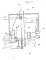
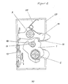
- a rotary latch 2 rotatable about an axis 3 is arranged in its locking position.
- a cam disk 4 and an actuating lever 5 extending radially away from the axis 3 are fixedly connected to the axis 3 of the rotary latch 2, and a piston rod 6 of a piston-cylinder unit 7 is articulated on the end opposite the axis 3.
- the piston-cylinder unit 7 consists of a chamber which is divided into an atmosphere chamber and an application chamber by a membrane connected to the piston rod 6.
- An admission line 8 opens into the admission chamber while the atmosphere chamber is permanently connected to the atmosphere.
- a pawl 10 rotatable about an axis 9 engages behind a latching element 11 of the rotary latch 2 in the illustrated locking position of the rotary latch 2 and thus secures the latter against turning clockwise in the opening direction.
- the pawl 10 can be moved manually via an actuating linkage 13 by means of the door handle 12 between the illustrated locking position and a release position releasing the latching element 11, the respective position of the pawl 10 being detectable by a locking detection 14 scanning the actuating linkage, from which a corresponding signal from an electronic unit 15 can be fed.
- a pre-latching detection 16 and a closing latching detection 17 on the cam disk 4 scan the respective position of the rotary latch 2 and transmit corresponding signals to the electronics unit 15.
- a bolt-shaped closing element 19 is located in a U-shaped recess 18 of the rotary latch 2, which is firmly connected to the door frame 20.
- a circumferential door seal 21 is arranged on the door frame 20 and extends along the contact area of the circumferential edge of the door.
- the door seal 21 is designed as a hollow tube profile, the inner chamber 22 of which can be pressurized via a door seal line 23.
- Both the door seal line 23 and the supply line 8 lead to a solenoid valve unit 24 which can be controlled by the electronics unit 15 operating as a control unit and via which the overpressure or underpressure of the piston-cylinder unit 7 and the door seal 21 generated by a pump 25 can be supplied.
- a pressure sensor 26 As further signals that can be processed by the electronics unit 15, these are generated by a pressure sensor 26, a pressure signal dependent on the pressure in the loading chamber of the piston-cylinder unit 7, a pressure sensor 27, a pressure signal dependent on the pressure in the inner chamber 22 of the door seal 21, and a vehicle speed sensor 33 Speed signal and a time signal supplied.
- the rotary latch 2 is pretensioned in the neutral position by a torsion spring 30 which engages the housing and the other end on the rotary latch 2.
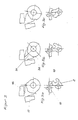
- FIG. 3 shows both the cam disk 4 with the pre-latching detection 16 and locking detent detection 17 acting thereon as well as the pawl 10 and the rotary latch 2, the neutral position being shown in FIG. 3a, the pre-latching position in FIG. 3b and the closing latching position being shown in FIG. 3c.
- the pre-latching detection 16 does not emit a signal in the neutral position, while a signal is emitted in the pre-latching position and in the closing latching position.
- the locking latch cam 32 controls the locking latch detection so that it emits no signal in the neutral position and in the locking position and a signal in the locking position.
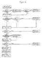
- the flow diagram shown in FIG. 4 represents the closing process of the closing aid shown in FIG. 1. It begins with the door and thus also the rotary latch 2 being moved from the neutral position into the pre-locking position by the locking element 19 and the pre-locking detection 16 thereby emitting a signal .
- the pump 25 generates an overpressure which is fed to the piston-cylinder unit 7 in order to move the rotary latch 2 from the pre-locking position into the closing locking position.
- Pressurization of the piston-cylinder unit 7 and returning the piston-cylinder unit 7 to the pre-latching position also takes place when the closing latching position has been reached by the rotary latch 2. However, this remains in the closing latching position, since it is held by the pawl 10 and because the piston-cylinder unit 7 moves in the opening direction from the catch 2 can be uncoupled.
- the signals of the locking detents of the other doors are used to check whether these are also closed.
- FIG. 5 shows a flow chart that describes the opening process of the closing aid. This is triggered in that the rotary latch 2 is moved into the neutral position by completely opening the door. The locking detent detection 17 therefore no longer emits a signal. As a result, the application of negative pressure to the door seal 21 is triggered until a certain desired negative pressure is reached. The pump 25 then switches off.
- a premature termination occurs when the latching position of the latch 2 is assumed again by moving the rotary latch 2 into the pre-latching position and the closing process thereby triggered, and the latching detection 17 thus again emits a signal.
Landscapes
- Lock And Its Accessories (AREA)
- Power-Operated Mechanisms For Wings (AREA)
Applications Claiming Priority (2)
| Application Number | Priority Date | Filing Date | Title |
|---|---|---|---|
| DE3728086 | 1987-08-22 | ||
| DE19873728086 DE3728086A1 (de) | 1987-08-22 | 1987-08-22 | Schliesshilfe fuer eine fahrzeugtuer |
Publications (3)
| Publication Number | Publication Date |
|---|---|
| EP0304542A2 true EP0304542A2 (fr) | 1989-03-01 |
| EP0304542A3 EP0304542A3 (en) | 1989-04-05 |
| EP0304542B1 EP0304542B1 (fr) | 1991-12-11 |
Family
ID=6334297
Family Applications (1)
| Application Number | Title | Priority Date | Filing Date |
|---|---|---|---|
| EP88106375A Expired - Lifetime EP0304542B1 (fr) | 1987-08-22 | 1988-04-21 | Dispositif de fermeture assisté pour porte de véhicule automobile |
Country Status (2)
| Country | Link |
|---|---|
| EP (1) | EP0304542B1 (fr) |
| DE (2) | DE3728086A1 (fr) |
Cited By (1)
| Publication number | Priority date | Publication date | Assignee | Title |
|---|---|---|---|---|
| DE4006126A1 (de) * | 1990-02-27 | 1991-08-29 | Daimler Benz Ag | Tuerschliesshilfeeinrichtung f. kraftfahrzeuge |
Families Citing this family (6)
| Publication number | Priority date | Publication date | Assignee | Title |
|---|---|---|---|---|
| DE3931866C1 (fr) * | 1989-09-23 | 1991-03-21 | Mercedes-Benz Aktiengesellschaft, 7000 Stuttgart, De | |
| DE4218730B4 (de) * | 1992-04-29 | 2004-05-27 | Karl Fliether Gmbh & Co. Kg | Verschließeinrichtung für eine Gebäudeabschlußtür, insbesondere Gebäudeaußentür, sowie mit einer solchen Verschließeinrichtung versehene Gebäudeabschlußtür |
| DE19619958C2 (de) * | 1996-05-17 | 1999-10-21 | Valeo Gmbh & Co Schliessyst Kg | Schloß für eine Kraftfahrzeugtür |
| DE202008003674U1 (de) * | 2008-03-14 | 2009-08-27 | Kiekert Ag | Kraftfahrzeugtür |
| DE102010006490A1 (de) | 2010-02-02 | 2011-04-28 | Audi Ag | Verfahren und Vorrichtung zum Abdichten einer Fahrzeugklappe gegenüber einer Fahrzeugkarosserie |
| DE102020110769A1 (de) * | 2020-04-21 | 2021-10-21 | Daimler Ag | Verfahren zur sicheren Erkennung einer Schließposition eines beweglichen Teils von einem Fahrzeug |
Family Cites Families (2)
| Publication number | Priority date | Publication date | Assignee | Title |
|---|---|---|---|---|
| DE1919148C3 (de) * | 1969-04-15 | 1978-07-06 | Pfeiffer, Hans Walter, 5970 Plettenberg | Pneumatisch oder hydraulisch betätigbare Schließhilfe für einen Fahrzeug- Türverschluß mit Drehfalle |
| DE2906860A1 (de) * | 1979-02-22 | 1980-09-04 | Egon Ing Grad Gelhard | Schliess- und/oder verriegelungseinrichtung fuer fahrzeugtueren |
-
1987
- 1987-08-22 DE DE19873728086 patent/DE3728086A1/de not_active Withdrawn
-
1988
- 1988-04-21 EP EP88106375A patent/EP0304542B1/fr not_active Expired - Lifetime
- 1988-04-21 DE DE8888106375T patent/DE3866827D1/de not_active Expired - Lifetime
Cited By (1)
| Publication number | Priority date | Publication date | Assignee | Title |
|---|---|---|---|---|
| DE4006126A1 (de) * | 1990-02-27 | 1991-08-29 | Daimler Benz Ag | Tuerschliesshilfeeinrichtung f. kraftfahrzeuge |
Also Published As
| Publication number | Publication date |
|---|---|
| EP0304542A3 (en) | 1989-04-05 |
| DE3866827D1 (de) | 1992-01-23 |
| DE3728086A1 (de) | 1989-03-02 |
| EP0304542B1 (fr) | 1991-12-11 |
Similar Documents
| Publication | Publication Date | Title |
|---|---|---|
| WO2023110023A1 (fr) | Ensemble porte de véhicule automobile | |
| DE1236755B (de) | Vorrichtung zum Heben von insbesondere flaechigem Gut mit einem als Zylinder-Kolben-Anordnung ausgefuehrten Saugkopf | |
| DE3728086A1 (de) | Schliesshilfe fuer eine fahrzeugtuer | |
| WO2005005757A1 (fr) | Serrure de portiere de vehicule automobile | |
| DE3912778C2 (de) | Türbetätigungseinrichtung | |
| EP1072749A2 (fr) | Actionnement électromécanique pour tourillon pour le movement du battant d'une porte palière d'un vehicule notamment d'un vehicule de transport public. | |
| EP1477627A2 (fr) | Serrure de porte pour véhicule automobile | |
| DE4105544C1 (fr) | ||
| EP0520166A1 (fr) | Circuit de commande pour l'ouverture assistée d'une porte en cas d'urgence | |
| DE3344444C2 (fr) | ||
| DE19628149B4 (de) | Einrichtung an einem Kraftfahrzeug mit Heckklappe | |
| DE1919148C3 (de) | Pneumatisch oder hydraulisch betätigbare Schließhilfe für einen Fahrzeug- Türverschluß mit Drehfalle | |
| DE1555038B2 (de) | Kombinierte betriebs-hilfs- bzw. standbremseinrichtung fuer kraftfahrzeuge | |
| AT328327B (de) | Pneumatische stellvorrichtung | |
| DE2530172C2 (de) | Pneumatische Türbetätigungseinrichtung, insbesondere für Fahrzeuge | |
| EP1931849A2 (fr) | Porte equipee d'un frein de porte | |
| DE3803836A1 (de) | Einrichtung zum ent- und verriegeln von tueren, insbesondere kraftfahrzeugtueren | |
| DE4243150C2 (de) | Schloß für eine Tür oder Klappe in einem Fahrzeug | |
| DE4118659B4 (de) | Schaltgetriebe zur Betätigung von Stellmitteln in Druckmaschinen | |
| DE102023116261A1 (de) | Kraftfahrzeug-Schloss | |
| EP0023531B1 (fr) | Dispositif pour soulever et abaisser des plateformes de levage en utilisant la pression d'un fluide | |
| DE102023110558A1 (de) | Kraftfahrzeug-Schloss | |
| AT247555B (de) | Vorrichtung zum Heben von insbesondere flächigem Gut | |
| DE1605227C3 (de) | Selbsttätig wirkende Steuerein richtung zum Betatigen von Ablaßven tilen in Druckmittelbremseinnchtungen von Schienenfahrzeugen | |
| DE20211915U1 (de) | Stellantrieb für eine Armatur |
Legal Events
| Date | Code | Title | Description |
|---|---|---|---|
| PUAI | Public reference made under article 153(3) epc to a published international application that has entered the european phase |
Free format text: ORIGINAL CODE: 0009012 |
|
| PUAL | Search report despatched |
Free format text: ORIGINAL CODE: 0009013 |
|
| AK | Designated contracting states |
Kind code of ref document: A2 Designated state(s): DE FR GB IT |
|
| AK | Designated contracting states |
Kind code of ref document: A3 Designated state(s): DE FR GB IT |
|
| 17P | Request for examination filed |
Effective date: 19890221 |
|
| 17Q | First examination report despatched |
Effective date: 19900806 |
|
| GRAA | (expected) grant |
Free format text: ORIGINAL CODE: 0009210 |
|
| AK | Designated contracting states |
Kind code of ref document: B1 Designated state(s): DE FR GB IT |
|
| ET | Fr: translation filed | ||
| REF | Corresponds to: |
Ref document number: 3866827 Country of ref document: DE Date of ref document: 19920123 |
|
| GBT | Gb: translation of ep patent filed (gb section 77(6)(a)/1977) | ||
| ITF | It: translation for a ep patent filed | ||
| PLBE | No opposition filed within time limit |
Free format text: ORIGINAL CODE: 0009261 |
|
| STAA | Information on the status of an ep patent application or granted ep patent |
Free format text: STATUS: NO OPPOSITION FILED WITHIN TIME LIMIT |
|
| 26N | No opposition filed | ||
| PGFP | Annual fee paid to national office [announced via postgrant information from national office to epo] |
Ref country code: GB Payment date: 19930315 Year of fee payment: 6 |
|
| PGFP | Annual fee paid to national office [announced via postgrant information from national office to epo] |
Ref country code: FR Payment date: 19930317 Year of fee payment: 6 |
|
| PG25 | Lapsed in a contracting state [announced via postgrant information from national office to epo] |
Ref country code: GB Effective date: 19940421 |
|
| GBPC | Gb: european patent ceased through non-payment of renewal fee |
Effective date: 19940421 |
|
| PG25 | Lapsed in a contracting state [announced via postgrant information from national office to epo] |
Ref country code: FR Effective date: 19941229 |
|
| REG | Reference to a national code |
Ref country code: FR Ref legal event code: ST |
|
| PGFP | Annual fee paid to national office [announced via postgrant information from national office to epo] |
Ref country code: DE Payment date: 19950302 Year of fee payment: 8 |
|
| PG25 | Lapsed in a contracting state [announced via postgrant information from national office to epo] |
Ref country code: DE Effective date: 19970101 |
|
| PG25 | Lapsed in a contracting state [announced via postgrant information from national office to epo] |
Ref country code: IT Free format text: LAPSE BECAUSE OF NON-PAYMENT OF DUE FEES Effective date: 20050421 |