EP0304553A2 - Moteur à combustion interne - Google Patents
Moteur à combustion interne Download PDFInfo
- Publication number
- EP0304553A2 EP0304553A2 EP88108243A EP88108243A EP0304553A2 EP 0304553 A2 EP0304553 A2 EP 0304553A2 EP 88108243 A EP88108243 A EP 88108243A EP 88108243 A EP88108243 A EP 88108243A EP 0304553 A2 EP0304553 A2 EP 0304553A2
- Authority
- EP
- European Patent Office
- Prior art keywords
- combustion engine
- internal combustion
- engine according
- crankcase
- crankshaft
- Prior art date
- Legal status (The legal status is an assumption and is not a legal conclusion. Google has not performed a legal analysis and makes no representation as to the accuracy of the status listed.)
- Withdrawn
Links
Images
Classifications
-
- F—MECHANICAL ENGINEERING; LIGHTING; HEATING; WEAPONS; BLASTING
- F01—MACHINES OR ENGINES IN GENERAL; ENGINE PLANTS IN GENERAL; STEAM ENGINES
- F01M—LUBRICATING OF MACHINES OR ENGINES IN GENERAL; LUBRICATING INTERNAL COMBUSTION ENGINES; CRANKCASE VENTILATING
- F01M1/00—Pressure lubrication
- F01M1/02—Pressure lubrication using lubricating pumps
-
- F—MECHANICAL ENGINEERING; LIGHTING; HEATING; WEAPONS; BLASTING
- F02—COMBUSTION ENGINES; HOT-GAS OR COMBUSTION-PRODUCT ENGINE PLANTS
- F02B—INTERNAL-COMBUSTION PISTON ENGINES; COMBUSTION ENGINES IN GENERAL
- F02B75/00—Other engines
- F02B75/16—Engines characterised by number of cylinders, e.g. single-cylinder engines
- F02B75/18—Multi-cylinder engines
- F02B75/22—Multi-cylinder engines with cylinders in V, fan, or star arrangement
-
- F—MECHANICAL ENGINEERING; LIGHTING; HEATING; WEAPONS; BLASTING
- F02—COMBUSTION ENGINES; HOT-GAS OR COMBUSTION-PRODUCT ENGINE PLANTS
- F02B—INTERNAL-COMBUSTION PISTON ENGINES; COMBUSTION ENGINES IN GENERAL
- F02B77/00—Component parts, details or accessories, not otherwise provided for
- F02B77/11—Thermal or acoustic insulation
- F02B77/13—Acoustic insulation
-
- F—MECHANICAL ENGINEERING; LIGHTING; HEATING; WEAPONS; BLASTING
- F02—COMBUSTION ENGINES; HOT-GAS OR COMBUSTION-PRODUCT ENGINE PLANTS
- F02F—CYLINDERS, PISTONS OR CASINGS, FOR COMBUSTION ENGINES; ARRANGEMENTS OF SEALINGS IN COMBUSTION ENGINES
- F02F7/00—Casings, e.g. crankcases
- F02F7/0065—Shape of casings for other machine parts and purposes, e.g. utilisation purposes, safety
- F02F7/0073—Adaptations for fitting the engine, e.g. front-plates or bell-housings
Definitions
- the invention relates to an internal combustion engine according to the preamble of claim 1.
- the object of the invention is to provide an internal combustion engine whose crankcase and crankshaft are designed on one end face in such a way that auxiliary units and / or endless links of the internal combustion engine are covered in a cost-effective and weight-saving manner with functional drive in a noise-free manner.
- the main advantages achieved with the invention can be seen in the fact that the cladding, the auxiliary units and endless links on the end face of the crankcase cover with little noise.
- the cladding formed by two relatively thin-walled sheet metal layers is easy to manufacture and lightweight. In addition, it easily absorbs thermal expansion of the light metal crankcase, for example.
- extension connected to the crankshaft, not only a short construction is possible with the said crankshaft, but the drive of the auxiliary units and the endless links can be carried out effectively realize.
- the extension also helps to simplify the assembly of the auxiliary units and / or endless links.
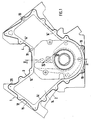
- An internal combustion engine 1 comprises a crankcase 2, which has two integrally formed cylinder rows 3, 4 - V-type - and is designed to receive a crankshaft 5.
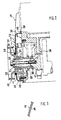
- the crankshaft 5 is configured adjacent to an end face 6 of the crankcase for driving auxiliary units, such as oil pump 7 and alternator, as well as endless members 8, 9.
- a drive wheel 10 connected to the crankshaft 5 interacts with the alternator, not shown; the endless links 8, 9 with camshafts, also not shown, arranged above the cylinders.
- the oil pump 7 projects with a housing 11 beyond the end face 6 of the crankcase 2 and is attached to the crankcase 2 at 12 by means of screws 13.
- crankcase 2 To assemble the endless members 8, 9 and their tensioning and / or sliding devices, the crankcase 2 has an opening 14 on the end face 6, which is delimited by a wall 14 '.
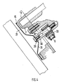
- the endless links 8, 9 and the oil pump 7 are covered by a cladding 15, which consists of sheet metal and in fact consists of two thin-walled, contacting layers 16, 17 (FIG. 3).
- the thickness of the layers 16, 17 is approximately 0.5 mm.
- the lining 15 is cup-shaped (FIG. 2), whereby it is formed by means of an edge flange 18 runs along the wall 14 'of the crankcase 2 and a plurality of screws 19 is attached to the end face.
- the cladding 15 is supported on the outside of the housing 11 by a section 20 of a base wall 21 and by means of a sealing body 22.
- the section 20 has an expression 23 which is guided away from the base wall 21 and the housing 11 has a recess 24.
- the base wall 21 is also provided with an opening 25 within the expression 23.
- the covering 15 has between the edge flange 18 and the base wall 21 a frame-like wall 26 which extends perpendicular to the edge flange 18.
- the base wall 21 is convexly curved at least locally (see at 27). The bend 28 on the free side of the edge flange 18 serves the same purpose.
- the base wall 21 is also fastened by means of a screw 29 to a fixed part 30 of the crankcase 2.
- the base wall 21 has an indentation 31 there.
- the fixed part 30 is a fastening pin 32 for a tensioning and / or sliding rail 33 of the endless member 9.
- crankshaft 5 ends in the area of a bearing block 35 of the crankcase 2, the bearing block 35 running at a parallel distance from the end face 6.
- a sleeve-like axial extension 36 of the crankshaft 5 is used to drive the oil pump 7, including the endless links 8, 9.
- the extension 36 which is a separate component, cooperates with the oil pump 7 at 37 and is provided with a drive wheel 38 for the endless link 9 provided.
- Another drive wheel 39 for the endless member 8 is shown in the exemplary embodiment as a separate component which is connected to the crankshaft 5 in a rotationally fixed manner. But this can also be made in one piece with the extension 36.
- the extension 36 and the crankshaft 5 are connected by means of a screw 40, which is effective in the axial direction of the crankshaft 5, that is, it is screwed into an axial threaded bore 41 of this shaft.
- the screw 40 clamps by means of a washer 42 and the drive wheel 10 (for the alternator), the extension 36 against the crankshaft 5.
Landscapes
- Engineering & Computer Science (AREA)
- Mechanical Engineering (AREA)
- General Engineering & Computer Science (AREA)
- Chemical & Material Sciences (AREA)
- Combustion & Propulsion (AREA)
- Physics & Mathematics (AREA)
- Acoustics & Sound (AREA)
- Cylinder Crankcases Of Internal Combustion Engines (AREA)
- Lubrication Details And Ventilation Of Internal Combustion Engines (AREA)
- Lubrication Of Internal Combustion Engines (AREA)
Applications Claiming Priority (2)
| Application Number | Priority Date | Filing Date | Title |
|---|---|---|---|
| DE3728268 | 1987-08-25 | ||
| DE19873728268 DE3728268A1 (de) | 1987-08-25 | 1987-08-25 | Brennkraftmaschine |
Publications (2)
| Publication Number | Publication Date |
|---|---|
| EP0304553A2 true EP0304553A2 (fr) | 1989-03-01 |
| EP0304553A3 EP0304553A3 (fr) | 1989-07-26 |
Family
ID=6334407
Family Applications (1)
| Application Number | Title | Priority Date | Filing Date |
|---|---|---|---|
| EP88108243A Withdrawn EP0304553A3 (fr) | 1987-08-25 | 1988-05-24 | Moteur à combustion interne |
Country Status (4)
| Country | Link |
|---|---|
| US (1) | US4883031A (fr) |
| EP (1) | EP0304553A3 (fr) |
| JP (1) | JPS6466425A (fr) |
| DE (1) | DE3728268A1 (fr) |
Cited By (1)
| Publication number | Priority date | Publication date | Assignee | Title |
|---|---|---|---|---|
| DE19630545A1 (de) * | 1995-07-20 | 1997-02-06 | Suzuki Motor Co | Ölpumpenzahnkranzabdeckung für einen Verbrennungsmotor |
Families Citing this family (15)
| Publication number | Priority date | Publication date | Assignee | Title |
|---|---|---|---|---|
| JPH02169808A (ja) * | 1988-12-21 | 1990-06-29 | Nissan Motor Co Ltd | Dohc機関のカム軸駆動装置 |
| JPH02173303A (ja) * | 1988-12-26 | 1990-07-04 | Nissan Motor Co Ltd | Dohc機関のカム軸駆動装置 |
| JPH07111146B2 (ja) * | 1989-02-08 | 1995-11-29 | 日産自動車株式会社 | 内燃機関のチェーンカバー装置 |
| JP2507024B2 (ja) * | 1989-02-17 | 1996-06-12 | 日産自動車株式会社 | エンジンのケ―シング装置 |
| JPH0351110U (fr) * | 1989-09-26 | 1991-05-17 | ||
| US4998515A (en) * | 1990-04-20 | 1991-03-12 | Kcr Engine Automotive Parts, Inc. | Internal combustion engine timing chain cover |
| DE4400953C2 (de) * | 1994-01-14 | 1997-06-05 | Daimler Benz Ag | Schmierölvorrichtung für eine Brennkraftmaschine |
| JP3261263B2 (ja) * | 1994-07-12 | 2002-02-25 | 本田技研工業株式会社 | 鞍乗型車両用パワーユニット |
| JP2001200754A (ja) * | 2000-01-17 | 2001-07-27 | Honda Motor Co Ltd | エンジン |
| JP3894728B2 (ja) * | 2000-12-28 | 2007-03-22 | 本田技研工業株式会社 | エンジンにおける動弁用タイミング伝動装置 |
| DE102004049030B4 (de) * | 2004-10-08 | 2008-09-11 | Audi Ag | Anordnung eines Steuergehäusedeckels |
| US7610893B2 (en) * | 2006-02-10 | 2009-11-03 | Federal-Mogul Worldwide, Inc. | Plastic cover having metal reinforcement for internal combustion engine applications and method of construction |
| FR2942507B1 (fr) * | 2009-02-26 | 2011-04-08 | Peugeot Citroen Automobiles Sa | Moteur a architecture en v a culasses rapprochees, joint et plaque de fermeture s'y rapportant |
| AT507477B1 (de) * | 2009-12-03 | 2011-07-15 | Avl List Gmbh | Brennkraftmaschine mit einem zylinderkopf und einem zylinderblock |
| US8863721B2 (en) | 2012-11-30 | 2014-10-21 | GM Global Technology Operations LLC | Seal alignment systems |
Family Cites Families (18)
| Publication number | Priority date | Publication date | Assignee | Title |
|---|---|---|---|---|
| FR18655E (fr) * | 1913-05-05 | 1914-05-30 | Ets De Dion Bouton | Pompe de graissage pour moteurs à explosions |
| US2303093A (en) * | 1940-07-29 | 1942-11-24 | Fairbanks Morse & Co | Internal combustion engine |
| US3096849A (en) * | 1960-03-24 | 1963-07-09 | Gen Motors Corp | Gear pump for internal combustion engine and the like |
| DE1576345A1 (de) * | 1967-09-06 | 1970-02-12 | Auto Union Gmbh | Anordnung einer Schmieroelpumpe bei Brennkraftmaschinen |
| GB1326211A (en) * | 1970-02-25 | 1973-08-08 | Cav Ltd | Internal combustion engine |
| AT365306B (de) * | 1976-09-17 | 1982-01-11 | List Hans | Brennkraftmaschine |
| DE7631631U1 (de) * | 1976-10-09 | 1977-01-20 | Steyr-Daimler-Puch Ag, Wien | Raederkasten fuer brennkraftmaschinen |
| AT365308B (de) * | 1977-05-06 | 1982-01-11 | List Hans | Schalldaemmend gekapselte maschine, insbesondere brennkraftmaschine |
| AT365309B (de) * | 1977-08-18 | 1982-01-11 | List Hans | Brennkraftmaschine mit schalldaemmender verschalung |
| US4257370A (en) * | 1978-12-29 | 1981-03-24 | Cummins Engine Company, Inc. | Combined gear cover and mount for an internal combustion engine |
| DE2916277A1 (de) * | 1979-04-21 | 1980-10-30 | Daimler Benz Ag | Flanschverbindung eines verbrennungsmotors |
| JPS601236Y2 (ja) * | 1980-09-22 | 1985-01-14 | 日産自動車株式会社 | エンジン表面遮蔽板 |
| JPS5773330U (fr) * | 1980-10-23 | 1982-05-06 | ||
| DE3232602A1 (de) * | 1982-09-02 | 1984-03-08 | Walker Deutschland GmbH Fahrzeugteile Division, 6800 Mannheim | Tiefgezogene motorenteile aus stahlblech |
| JPS5974312A (ja) * | 1982-10-20 | 1984-04-26 | Honda Motor Co Ltd | V型エンジンの動弁装置 |
| JPS5997392A (ja) * | 1982-11-24 | 1984-06-05 | 本田技研工業株式会社 | 内燃機関のクランクシヤフト軸受装置 |
| JPS59125646U (ja) * | 1983-02-12 | 1984-08-24 | トヨタ自動車株式会社 | タイミングベルトカバ−のシ−ル装置 |
| FR2545193B1 (fr) * | 1983-04-29 | 1986-10-31 | Sedis Transmissions Mecaniques | Boitier amovible de distribution pour moteur a explosion ou a combustion |
-
1987
- 1987-08-25 DE DE19873728268 patent/DE3728268A1/de active Granted
-
1988
- 1988-05-24 EP EP88108243A patent/EP0304553A3/fr not_active Withdrawn
- 1988-08-09 US US07/230,019 patent/US4883031A/en not_active Expired - Fee Related
- 1988-08-18 JP JP63203966A patent/JPS6466425A/ja active Pending
Cited By (2)
| Publication number | Priority date | Publication date | Assignee | Title |
|---|---|---|---|---|
| DE19630545A1 (de) * | 1995-07-20 | 1997-02-06 | Suzuki Motor Co | Ölpumpenzahnkranzabdeckung für einen Verbrennungsmotor |
| DE19630545B4 (de) * | 1995-07-20 | 2005-12-22 | Suzuki Motor Corp., Hamamatsu | Verbrennungsmotor mit Ölpumpenzahnkranzabdeckung |
Also Published As
| Publication number | Publication date |
|---|---|
| EP0304553A3 (fr) | 1989-07-26 |
| DE3728268C2 (fr) | 1990-05-03 |
| US4883031A (en) | 1989-11-28 |
| JPS6466425A (en) | 1989-03-13 |
| DE3728268A1 (de) | 1989-03-09 |
Similar Documents
| Publication | Publication Date | Title |
|---|---|---|
| DE3728268C2 (fr) | ||
| DE10159087C2 (de) | Brennkraftmaschine | |
| AT402088B (de) | Brennkraftmaschine mit in reihe angeordneten zylindern und einer obenliegenden nockenwelle zur betätigung der ein- und/oder auslassventile | |
| EP0987405B1 (fr) | Transmission par chaine pour moteur à combustion interne | |
| DE61778T1 (de) | Zylinderkopfbefestigungsanordnung fuer eine brennkraftmaschine. | |
| DE10244891B4 (de) | Montagevorrichtung für einen V-Motor | |
| EP0294559B1 (fr) | Tendeur de chaîne | |
| DE3810188A1 (de) | Laufschiene zum spannen einer transmission | |
| EP0979929A2 (fr) | Moteur à piston à commande de soupape par culbuteur | |
| EP0809041A2 (fr) | Dispositif d'équilibrage de torsion inertiel des moteurs à combustion interne | |
| DE4011424C2 (fr) | ||
| DE4136033A1 (de) | Brennkraftmaschine | |
| DE3142458C2 (de) | Brennkraftmaschine | |
| DE19719732C1 (de) | Gleitschiene für einen Kettentrieb | |
| DE3417100C2 (de) | Kettenführung für eine Steuerkette zum Antrieb einer Nockenwelle | |
| DE10021220A1 (de) | Brennkraftmaschine mit einem Kettentrieb | |
| EP1085173B1 (fr) | Entraînement de soupapes pour un moteur à combustion interne | |
| DE3643673C2 (fr) | ||
| DE19908287A1 (de) | Kettentrieb für Brennkraftmaschinen | |
| DE3225975C1 (de) | Zusammengesetzte Kurbelwelle | |
| DE69709466T2 (de) | Zylinderkopf einer Brennkraftmaschine mit einer Vorrichtung zum Spannen einer Treibkette zum Verbinden von zwei Nockenwellen | |
| DE19938279B4 (de) | Brennkraftmaschine | |
| DE19955431B4 (de) | Zylinderkopf für eine Brennkraftmaschine | |
| DE68906014T2 (de) | Steuervorrichtungsanordnung fuer eine mehrzylindrische brennkraftmaschine, insbesondere fuer kraftfahrzeuge. | |
| DE3814544A1 (de) | Parallelkurbelgetriebe fuer den antrieb zweier obenliegender nockenwellen pro zylinderreihe einer brennkraftmaschine |
Legal Events
| Date | Code | Title | Description |
|---|---|---|---|
| PUAI | Public reference made under article 153(3) epc to a published international application that has entered the european phase |
Free format text: ORIGINAL CODE: 0009012 |
|
| AK | Designated contracting states |
Kind code of ref document: A2 Designated state(s): DE FR GB IT |
|
| PUAL | Search report despatched |
Free format text: ORIGINAL CODE: 0009013 |
|
| AK | Designated contracting states |
Kind code of ref document: A3 Designated state(s): DE FR GB IT |
|
| 17P | Request for examination filed |
Effective date: 19891202 |
|
| 17Q | First examination report despatched |
Effective date: 19900831 |
|
| STAA | Information on the status of an ep patent application or granted ep patent |
Free format text: STATUS: THE APPLICATION HAS BEEN WITHDRAWN |
|
| 18W | Application withdrawn |
Withdrawal date: 19910516 |