EP0304700A1 - Vorrichtung zur Applikation von Implantaten - Google Patents
Vorrichtung zur Applikation von Implantaten Download PDFInfo
- Publication number
- EP0304700A1 EP0304700A1 EP88112758A EP88112758A EP0304700A1 EP 0304700 A1 EP0304700 A1 EP 0304700A1 EP 88112758 A EP88112758 A EP 88112758A EP 88112758 A EP88112758 A EP 88112758A EP 0304700 A1 EP0304700 A1 EP 0304700A1
- Authority
- EP
- European Patent Office
- Prior art keywords
- push rod
- active substance
- cannula
- tappet
- implants
- Prior art date
- Legal status (The legal status is an assumption and is not a legal conclusion. Google has not performed a legal analysis and makes no representation as to the accuracy of the status listed.)
- Granted
Links
- 239000007943 implant Substances 0.000 title claims abstract description 15
- 230000001681 protective effect Effects 0.000 claims abstract description 14
- 239000013543 active substance Substances 0.000 claims description 21
- 229920003023 plastic Polymers 0.000 claims description 9
- 206010033675 panniculitis Diseases 0.000 claims description 6
- 210000004304 subcutaneous tissue Anatomy 0.000 claims description 6
- 239000003814 drug Substances 0.000 claims description 3
- 238000002347 injection Methods 0.000 claims description 3
- 239000007924 injection Substances 0.000 claims description 3
- 229920001343 polytetrafluoroethylene Polymers 0.000 claims description 3
- 239000004810 polytetrafluoroethylene Substances 0.000 claims description 3
- 229940079593 drug Drugs 0.000 claims description 2
- 229920001296 polysiloxane Polymers 0.000 claims description 2
- -1 polytetrafluoroethylene Polymers 0.000 claims description 2
- 210000003205 muscle Anatomy 0.000 claims 1
- 201000010099 disease Diseases 0.000 abstract description 2
- 208000037265 diseases, disorders, signs and symptoms Diseases 0.000 abstract description 2
- 238000011866 long-term treatment Methods 0.000 abstract description 2
- 210000001519 tissue Anatomy 0.000 description 6
- 239000004033 plastic Substances 0.000 description 5
- 229920000515 polycarbonate Polymers 0.000 description 4
- 239000004417 polycarbonate Substances 0.000 description 3
- 239000004480 active ingredient Substances 0.000 description 2
- 150000002148 esters Chemical class 0.000 description 2
- 238000002513 implantation Methods 0.000 description 2
- 230000036512 infertility Effects 0.000 description 2
- 238000000034 method Methods 0.000 description 2
- 208000031872 Body Remains Diseases 0.000 description 1
- 208000017667 Chronic Disease Diseases 0.000 description 1
- BLCLNMBMMGCOAS-URPVMXJPSA-N Goserelin Chemical compound C([C@@H](C(=O)N[C@H](COC(C)(C)C)C(=O)N[C@@H](CC(C)C)C(=O)N[C@@H](CCCN=C(N)N)C(=O)N1[C@@H](CCC1)C(=O)NNC(N)=O)NC(=O)[C@H](CO)NC(=O)[C@H](CC=1C2=CC=CC=C2NC=1)NC(=O)[C@H](CC=1NC=NC=1)NC(=O)[C@H]1NC(=O)CC1)C1=CC=C(O)C=C1 BLCLNMBMMGCOAS-URPVMXJPSA-N 0.000 description 1
- 108010069236 Goserelin Proteins 0.000 description 1
- 206010061218 Inflammation Diseases 0.000 description 1
- 239000004425 Makrolon Substances 0.000 description 1
- 208000037273 Pathologic Processes Diseases 0.000 description 1
- 239000004952 Polyamide Substances 0.000 description 1
- 210000000683 abdominal cavity Anatomy 0.000 description 1
- 239000004621 biodegradable polymer Substances 0.000 description 1
- 229920002988 biodegradable polymer Polymers 0.000 description 1
- IISBACLAFKSPIT-UHFFFAOYSA-N bisphenol A Chemical compound C=1C=C(O)C=CC=1C(C)(C)C1=CC=C(O)C=C1 IISBACLAFKSPIT-UHFFFAOYSA-N 0.000 description 1
- 239000000599 controlled substance Substances 0.000 description 1
- 208000031513 cyst Diseases 0.000 description 1
- 239000002552 dosage form Substances 0.000 description 1
- 238000012377 drug delivery Methods 0.000 description 1
- 238000002651 drug therapy Methods 0.000 description 1
- 210000001214 frontal sinus Anatomy 0.000 description 1
- 238000001727 in vivo Methods 0.000 description 1
- 230000004054 inflammatory process Effects 0.000 description 1
- 238000010255 intramuscular injection Methods 0.000 description 1
- 239000007927 intramuscular injection Substances 0.000 description 1
- 230000007774 longterm Effects 0.000 description 1
- 239000000463 material Substances 0.000 description 1
- 239000002184 metal Substances 0.000 description 1
- 231100000252 nontoxic Toxicity 0.000 description 1
- 230000003000 nontoxic effect Effects 0.000 description 1
- 230000009054 pathological process Effects 0.000 description 1
- 229920002647 polyamide Polymers 0.000 description 1
- 230000001954 sterilising effect Effects 0.000 description 1
- 238000004659 sterilization and disinfection Methods 0.000 description 1
- 238000007920 subcutaneous administration Methods 0.000 description 1
- 238000010254 subcutaneous injection Methods 0.000 description 1
- 239000007929 subcutaneous injection Substances 0.000 description 1
- 238000002560 therapeutic procedure Methods 0.000 description 1
- 210000000115 thoracic cavity Anatomy 0.000 description 1
- 238000011282 treatment Methods 0.000 description 1
- 229940033942 zoladex Drugs 0.000 description 1
Images
Classifications
-
- A—HUMAN NECESSITIES
- A61—MEDICAL OR VETERINARY SCIENCE; HYGIENE
- A61M—DEVICES FOR INTRODUCING MEDIA INTO, OR ONTO, THE BODY; DEVICES FOR TRANSDUCING BODY MEDIA OR FOR TAKING MEDIA FROM THE BODY; DEVICES FOR PRODUCING OR ENDING SLEEP OR STUPOR
- A61M25/00—Catheters; Hollow probes
- A61M25/01—Introducing, guiding, advancing, emplacing or holding catheters
- A61M25/02—Holding devices, e.g. on the body
-
- A—HUMAN NECESSITIES
- A61—MEDICAL OR VETERINARY SCIENCE; HYGIENE
- A61M—DEVICES FOR INTRODUCING MEDIA INTO, OR ONTO, THE BODY; DEVICES FOR TRANSDUCING BODY MEDIA OR FOR TAKING MEDIA FROM THE BODY; DEVICES FOR PRODUCING OR ENDING SLEEP OR STUPOR
- A61M37/00—Other apparatus for introducing media into the body; Percutany, i.e. introducing medicines into the body by diffusion through the skin
- A61M37/0069—Devices for implanting pellets, e.g. markers or solid medicaments
Definitions
- the invention relates to a device for injecting implants, preferably rod-shaped implants (so-called rods), which are used for long-term treatment of diseases.
- implants preferably rod-shaped implants (so-called rods), which are used for long-term treatment of diseases.
- Devices for applying the active substance depot implants which are usually designed as cylindrical rods (rods), are already known. They usually consist of an active substance container in which the "rod” is located, an injection cannula attached to it and a plunger for introducing the active substance preparation by advancing it into the subcutaneous tissue.
- German laid-open specification 34 19 876 describes a mechanically relatively complex device for the subcutaneous application of depot bodies, in which the Depot body is located directly in front of the pointed cannula opening.
- the cannula is inserted into the subcutaneous tissue.
- the needle is then pulled out of the tissue by means of a displaceable member, a fixed push rod, which lies against the depot body, ensuring that the cannula alone retracts concentrically around the depot body and push rod and the depot body remains in the tissue.
- the depot body is therefore not pushed into the subcutaneous tissue, but is "exposed" in the tissue by the hollow cylindrical cannula pulling over it.
- the invention accordingly relates to: A device for injecting implants, consisting of an active substance container, a cannula and a push rod, characterized in that the cylindrical plunger channel, which runs through the active substance container (injector body), has a flexible O-shaped tube that runs concentrically around the plunger channel. Contains ring which slightly reduces the inner diameter of the cylindrical tappet channel and in that the push rod has a concentric groove and in that the device is further provided with a protective cap for both the cannula and the push rod and in that at least the active substance container clear plastic is made.
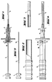
- FIGS. 1-5 The invention is explained in more detail in FIGS. 1-5.
- the device is shown without protective caps for push rod and cannula.
- the active substance cylinder (4) is located in the injector body (3) in front of the opening or already partially in the cannula (5).
- the active substance cylinder (4) is pushed into the subcutaneous tissue by means of the push rod (2), on the end of which is opposite the cannula is the push button (1).
- the one-piece injector body (3) is made of transparent plastic.
- the push rod and the cannula are made of metal.
- FIG. 4 shows the entire device with attached protective caps (6 and 7) is shown both for the push rod and for the cannula.
- Figure 5 shows the push rod (2) with the groove (10).
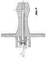
- FIG. 6 shows the central region of FIG. 1 in an enlarged detail.
- the active substance container (3) contains a flexible O-ring (9) which runs concentrically around the tappet channel (B) and which slightly reduces the inside diameter of the cylindrical tappet channel. This reduction in the inside diameter is 5-40%, preferably 10-30%, in particular 10-20%, of the diameter of the tappet channel.
- the push rod (2) itself has an annular groove (10) (concentric around the push rod), the depth of which is preferably 2.5 to 25%, particularly preferably 5 to 20%, very particularly preferably 7.5 to 12.5% of the diameter of the push rod.
- the remaining configurations of the device are freely variable depending on the area of application and can be adapted to the respective requirements by a person skilled in the art.
- the device is manufactured using generally customary methods of plastics processing.
- the O-ring (9) can be introduced concentrically into the tappet channel (8) of the active substance container (3), for example, by placing the O-ring on the nozzle (12) projecting over the active substance container and via the O-ring and the Socket sets a cap (11) which is, for example, clamped or glued to the socket.
- the fully transparent design in particular of the injector body, means that the presence and nature of the implant and the function of the device can be checked by the user at any time during the implantation process.
- the ring snaps into the groove, so to speak, so that further unintentional pulling out of the push rod is avoided.
- the protective cap for the push rod is primarily used to secure the push rod during injection in order to avoid unintentional actuation of the push rod. In addition, however, it also keeps the part of the device covered by it sterile, so that the device according to the invention remains sterile even when "unpacked" (see FIG. 4).
- the implantation device can be easily operated by the user with one hand, as this corresponds to the practical requirements of the treatment.
- the cannula protective cap is first removed from the device as shown in FIG. 4.
- the cannula is then inserted into the skin tissue. Only now is the protective cap (6) of the push rod removed and, if necessary after the cannula has been partially withdrawn from the tissue, the implant is placed in the tissue by completely pushing the push rod.
- the field of application relates to the subcutaneous or intramuscular injection of drug-containing "rods" made of biodegradable polymer material with the dimensions 0.6 mm to 3 mm in diameter and a length of 0.5 to 30 mm. It can also be used by inserting the implants into joints or body cavities.
- the body cavity must be accessible with the cannula and allow the active ingredient to be removed. Examples include: frontal sinus, chest cavity, abdominal cavity or cysts or cavities caused by inflammation or other pathological processes.
Landscapes
- Health & Medical Sciences (AREA)
- Engineering & Computer Science (AREA)
- Life Sciences & Earth Sciences (AREA)
- Veterinary Medicine (AREA)
- Anesthesiology (AREA)
- Biomedical Technology (AREA)
- Heart & Thoracic Surgery (AREA)
- Hematology (AREA)
- Animal Behavior & Ethology (AREA)
- General Health & Medical Sciences (AREA)
- Public Health (AREA)
- Medical Informatics (AREA)
- Dermatology (AREA)
- Pulmonology (AREA)
- Biophysics (AREA)
- Infusion, Injection, And Reservoir Apparatuses (AREA)
- Prostheses (AREA)
- Soil Working Implements (AREA)
- Media Introduction/Drainage Providing Device (AREA)
- External Artificial Organs (AREA)
- Pharmaceuticals Containing Other Organic And Inorganic Compounds (AREA)
- Non-Silver Salt Photosensitive Materials And Non-Silver Salt Photography (AREA)
- Materials For Medical Uses (AREA)
- Paper (AREA)
- Injection Moulding Of Plastics Or The Like (AREA)
- Seal Device For Vehicle (AREA)
- Electrotherapy Devices (AREA)
Abstract
Description
- Gegenstand der Erfindung ist eine Vorrichtung zur Injektion von Implantaten, bevorzugt stäbchenförmigen Implantaten (sogenannten Rods), die zur Langzeitbehandlung von Erkrankungen dienen.
- Die Applikation solcher Implantate hat in letzter Zeit Bedeutung erlangt, da Kunststoffe entwickelt wurden, die in vivo kontrolliert abgebaut werden und somit den matrixartig eingeschlossenen oder chemisch an sie gebundenen Wirkstoff über einen längeren Zeitraum an den Organismus abgeben (Wirkstoffdepotformen).
- Eine moderne Arzneitherapie kann auf diese Darreichungsformen, die eine kontrollierte Abgaberate der Wirkstoffe mit einer hohen Biokompatibilität des Depots vereinigen, nicht mehr verzichten. Eine solche langandauernde kontrollierte Wirkstoffabgabe ist wegen der zunehmenden Bedeutung chronischer Erkrankungen und langzeitorientierter Therapiekonzepte in Human- und Veterinärmedizin von großer Aktualität.
- Vorrichtungen zur Applikation der meist als zylindrische Stäbchen (Rods) ausgebildeten Wirkstoffdepot-Implantaten sind bereits bekannt. Sie bestehen meist aus einem Wirkstoffbehälter, in dem sich das "Rod" befindet, einer daran angesetzten Injektionskanüle und einem Stößel zur Einbringung der Wirkstoffzubereitung durch Vorschieben in das Subkutangewebe.
- In der deutschen Offenlegungsschrift 34 19 876 ist eine mechanisch relativ aufwendige Vorrichtung zur subkutanen Applikation von Depotkörpern beschrieben, bei der der Depotkörper sich unmittelbar vor der spitzen Kanülenöffnung befindet. Bei der Applikation wird die Kanüle in das Subkutangewebe eingeführt. Mittels eines verschiebbaren Glieds wird dann die Nadel aus dem Gewebe herausgezogen, wobei eine feststehende Stößelstange, die an dem Depotkörper anliegt, dafür sorgt, daß sich allein die Kanüle konzentrisch um Depotkörper und Stößelstange zurückzieht und der Depotkörper im Gewebe verbleibt. Der Depotkörper wird also nicht in das Subkutangewebe hineingeschoben, sondern wird im Gewebe "freigelegt", indem sich die hohlzylindrische Kanüle über ihn hinwegzieht.
- Aus der Produktinformation zum (R)ZOLADEX-Depot (ICI) ist eine Vorrichtung zur Applikation von Implantaten bekannt, bei der der Wirkstoffbehälter ein durchsichtiges Mittelteil (Fenster) enthält, so daß man erkennen kann, ob sich ein "Rod" in der Vorrichtung befindet oder nicht.
- Anwendungstechnisch weist der von ICI beschriebene Injektor jedoch eine Reihe von Nachteilen auf:
- a) Zwar befindet sich die gesamte Applikationsvorrichtung steril verpackt in einer Blisterpackung; einmal geöffnet muß die Vorrichtung aber möglichst schnell verwendet werden, da anderenfalls die Sterilität nicht mehr gewährleistet ist. Dabei wird unterstellt, daß die Kanüle noch mit einer Schutzkappe versehen ist, die Stößelstange jedoch bleibt im "ausgepackten" Zustand nicht steril, was dann von Nachteil sein kann, wenn die Stößelstange mehrfach hin und hergeschoben wird, wobei die Sterilität des Wirkstoffzylinders nicht mehr gewährleistet werden kann.
- b) Es besteht die Gefahr, daß beim Einführen der Kanüle in das Subkutangewebe, vorzeitig und unbeabsichtigt die Stößelstange betätigt wird.
- Diese Nachteile werden durch die nachfolgend aufgeführten konstruktiven Änderungen gegenüber dem oben beschriebenen ICI-Injektor vermieden.
- Die Erfindung betrifft dementsprechend: Eine Vorrichtung zur Injektion von Implantaten, bestehend aus einem Wirkstoffbehälter, einer Kanüle und einer Stößelstange, dadurch gekennzeichnet, daß der zylindrische Stößelkanal, der durch den Wirkstoffbehälter (Injektorkörper) verläuft, einen konzentrisch um den Stößelkanal verlaufenden, flexiblen O-Ring enthält, der den Innendurchmesser des zylindrischen Stößelkanals geringfügig verkleinert und dadurch, daß die Stößelstange eine konzentrische Nut aufweist und dadurch, daß die Vorrichtung weiterhin mit einer Schutzkappe sowohl für die Kanüle als auch für die Stößelstange versehen ist und dadurch, daß zumindest der Wirkstoffbehälter aus durchsichtigem Kunststoff gefertigt ist.
- In den Figuren 1 - 5 ist die Erfindung näher erläutert.
- In Figur 1 ist die Vorrichtung ohne Schutzkappen für Stößelstange und Kanüle dargestellt. In dem Injektorkörper (3) befindet sich der Wirkstoffzylinder (4) vor der Öffnung bzw. schon teilweise in der Kanüle (5). Das Vorschieben des Wirkstoffzylinders (4) in das Subkutangewebe erfolgt mittels der Stößelstange (2), an dessen der Kanüle entgegengesetzten Ende sich der Stößelknopf (1) befindet. Der einstückige Injektorkörper (3) ist aus durchsichtigem Kunststoff gefertigt. Die Stößelstange und die Kanüle sind aus Metall gefertigt.
- In der Figur 2 ist die Schutzkappe (6) für die Stößelstange und in der Figur 3 die Schutzkappe (7) für die Kanüle dargestellt. Beide Teile (6 und 7) können bevorzugt ebenfalls aus durchsichtigem Kunststoff gefertigt sein.
- In Figur 4 ist die gesamte Vorrichtung mit aufgesteckten Schutzkappen (6 und 7) sowohl für die Stößelstange als auch für die Kanüle dargestellt. Figur 5 zeigt die Stößelstange (2) mit der Nut (10).
Figur 6 zeigt in vergrößerter Detaildarstellung den Mittelbereich der Figur 1. - ErfindungsgemaB enthält der Wirkstoffbehälter (3) einen konzentrisch um den Stößelkanal (B) verlaufenden, flexiblen O-Ring (9), der den Innendurchmesser des zylindrischen Stößelkanals geringfügig verkleinert. Diese Verkleinerung des Innendurchmessers beträgt 5 - 40 %, bevorzugt 10 - 30 %, insbesondere 10 - 20 %, von dem Durchmesser des Stößelkanals. Die Stößelstange (2) selbst besitzt eine ringförmige (konzentrisch um die Stößelstange) verlaufende Nut (10), deren Tiefe bevorzugt 2,5 - 25 %, besonders bevorzugt 5 - 20 %, ganz besonders bevorzugt 7,5 - 12,5 % von dem Durchmesser der Stößelstange beträgt.
- Die restlichen Ausgestaltungen der Vorrichtung, wie Griffmulden für die Kanülen- bzw. Stößelstangenschutzkappen, Zeige- und Mittelfingergriffablage oder Stößelstangenknopf, sind je nach Anwendungsbereich frei variabel und vom Fachmann den jeweiligen Anforderungen anzupassen.
- Die Herstellung der Vorrichtung erfolgt nach allgemein üblichen Methoden der Kunststoffverarbeitung.
- Das konzentrische Einbringen des O-Rings (9) in den Stößelkanal (8) des Wirkstoffbehälters (3) kann beispielsweise erfolgen, indem man den O-Ring auf den über den Wirkstoffbehälter herausragenden Stutzen (12) auflegt und über den O-Ring und den Stutzen eine Kappe (11) setzt, die auf dem Stutzen beispielsweise verklemmt oder verklebt wird.
- Als Kunststoffe für die erfindungsgemäße Vorrichtung kommen solche in Betracht, die ungiftig, verschweißbar und sterilisierbar sind, insbesondere unempfindlich gegen Sterilisation mittels γ-Strahlen. Außerdem darf der verwendete Kunststoff mit keinem Bestandteil der verwendeten Implantate ("Rods") reagieren. Bevorzugt werden Polyamide oder Polycarbonate, insbesondere Polykohlensäureester von 4,4′-Dihydroxydiphenylalkanen, wie Polykohlensäureester des 4,4′-Dihydroxydiphenyl-2,2-propans ((R)Makrolon, Bayer) eingesetzt. Der flexible O-Ring besteht vorzugsweise aus Polytetrafluorethylen (PTFE) oder Silikon.
Wesentliche Merkmale der Vorrichtung sind: - a) die volldurchsichtige, einstückige Ausführung, insbesondere des Injektorkörpers,
- b) die Schutzkappe für die Stößelstange und
- c) die Schutzvorrichtung, die das Herausfallen der Stößelstange verhindert.
- Durch die volldurchsichtige Ausführung insbesondere des Injektorkörpers kann jederzeit das Vorhandensein und die Beschaffenheit des Implantats sowie die Funktion der Vorrichtung während des Implantationsvorganges durch den Anwender kontrolliert werden.
- Der konzentrisch um den Stößelkanal angeordnete flexible O-Ring sorgt in Verbindung mit der in der Stößelstange befindlichen Nut dafür, daß die Stößelstange nicht unbeabsichtigt aus dem Wirkstoffbehälter herausfällt bzw. gleichzeitig mit dem Abnehmen der Stößelstangenschutzkappe aus dem Wirkstoffbehälter herausgezogen wird. Der Ring rastet gewissermaßen in der Nut ein, so daß ein weiteres unbeabsichtigtes Herausziehen der Stößelstange vermieden wird.
- Die Schutzkappe für die Stößelstange dient in erster Linie zur Sicherung des Stößels während der Injektion, um eine unbeabsichtigte Betätigung des Stößels zu vermeiden. Darüberhinaus hält sie aber auch den von ihr abgedeckten Teil der Vorrichtung steril, so daß die erfindungsgemäße Vorrichtung auch "im ausgepackten Zustand" (s. Figur 4) weiterhin steril bleibt.
- Die Implantationsvorrichtung kann vom Anwender leicht mit einer Hand bedient werden, wie dies den praktischen Erfordernissen der Behandlung entspricht. Dazu wird von der Vorrichtung wie sie in Figur 4 dargestellt ist, zunächst die Kanülenschutzkappe entfernt. Daraufhin wird die Kanüle in das Hautgewebe eingeführt. Erst jetzt wird die Schutzkappe (6) der Stößelstange entfernt und - gegebenenfalls nach teilweiser Zurückziehung der Kanüle aus dem Gewebe - das Implantat durch vollständiges Durchdrücken der Stößelstange im Gewebe placiert.
- Der Anwendungsbereich betrifft die subkutane oder intramuskuläre Injektion von arzneimittelhaltigen "Rods" aus biologisch abbaubarem Polymermaterial mit den Abmessungen 0,6 mm bis 3 mm Durchmesser und einer Länge von 0,5 bis 30 mm. Die Anwendung kann auch durch Einbringung der Implantate in Gelenke oder Körperhöhlen erfolgen. Die Körperhöhle muß mit der Kanüle zugänglich sein und es ermöglichen, daß der Wirkstoff abtransportiert wird. Beispielsweise seien hier genannt: Stirnhöhle, Brusthöhle, Bauchhöhle oder Zysten oder durch Entzündungen oder andere krankhafte Prozesse entstandene Hohlräume.
Claims (8)
Priority Applications (1)
| Application Number | Priority Date | Filing Date | Title |
|---|---|---|---|
| AT88112758T ATE72406T1 (de) | 1987-08-11 | 1988-08-05 | Vorrichtung zur applikation von implantaten. |
Applications Claiming Priority (4)
| Application Number | Priority Date | Filing Date | Title |
|---|---|---|---|
| DE3726654 | 1987-08-11 | ||
| DE3726654 | 1987-08-11 | ||
| DE3802158A DE3802158A1 (de) | 1987-08-11 | 1988-01-26 | Vorrichtung zur applikation von implantaten |
| DE3802158 | 1988-01-26 |
Publications (2)
| Publication Number | Publication Date |
|---|---|
| EP0304700A1 true EP0304700A1 (de) | 1989-03-01 |
| EP0304700B1 EP0304700B1 (de) | 1992-02-05 |
Family
ID=25858504
Family Applications (1)
| Application Number | Title | Priority Date | Filing Date |
|---|---|---|---|
| EP88112758A Expired - Lifetime EP0304700B1 (de) | 1987-08-11 | 1988-08-05 | Vorrichtung zur Applikation von Implantaten |
Country Status (20)
| Country | Link |
|---|---|
| US (1) | US4941874A (de) |
| EP (1) | EP0304700B1 (de) |
| JP (1) | JP2635118B2 (de) |
| KR (1) | KR960015617B1 (de) |
| AT (1) | ATE72406T1 (de) |
| AU (1) | AU606983B2 (de) |
| CA (1) | CA1333982C (de) |
| DE (2) | DE3802158A1 (de) |
| DK (1) | DK168941B1 (de) |
| ES (1) | ES2030124T3 (de) |
| FI (1) | FI92909C (de) |
| GR (1) | GR3004431T3 (de) |
| HU (1) | HU199696B (de) |
| IE (1) | IE61885B1 (de) |
| IL (1) | IL87387A (de) |
| MX (1) | MX170115B (de) |
| NO (1) | NO171348C (de) |
| NZ (1) | NZ225748A (de) |
| PH (1) | PH26240A (de) |
| PT (1) | PT88222B (de) |
Cited By (7)
| Publication number | Priority date | Publication date | Assignee | Title |
|---|---|---|---|---|
| WO1993000127A1 (en) * | 1991-06-28 | 1993-01-07 | Brown University Research Foundation | Neural implant system |
| WO1994015663A1 (en) * | 1992-12-30 | 1994-07-21 | Brown University Research Foundation | Implantable therapy systems and methods |
| EP0631794A1 (de) * | 1993-06-23 | 1995-01-04 | Hoechst Aktiengesellschaft | Vorrichtung zum Applizieren von Implantaten |
| US5487739A (en) * | 1987-11-17 | 1996-01-30 | Brown University Research Foundation | Implantable therapy systems and methods |
| US5554148A (en) * | 1987-11-17 | 1996-09-10 | Brown University Research Foundation | Renewable neural implant device and method |
| EP0723465B1 (de) * | 1993-10-13 | 2000-02-09 | Leiras Oy | Injektionsvorrichtung für implantate |
| WO2008019267A3 (en) * | 2006-08-04 | 2008-04-03 | Allergan Inc | Ocular implant delivery assemblies with distal caps |
Families Citing this family (99)
| Publication number | Priority date | Publication date | Assignee | Title |
|---|---|---|---|---|
| US5773286A (en) * | 1987-11-17 | 1998-06-30 | Cytotherapeutics, Inc. | Inner supported biocompatible cell capsules |
| US5786216A (en) * | 1987-11-17 | 1998-07-28 | Cytotherapeutics, Inc. | Inner-supported, biocompatible cell capsules |
| SG49267A1 (en) * | 1989-08-14 | 1998-05-18 | Photogenesis Inc | Surgical instrument and cell isolation and transplantation |
| US6514238B1 (en) * | 1989-08-14 | 2003-02-04 | Photogenesis, Inc. | Method for preparation and transplantation of volute grafts and surgical instrument therefor |
| US5284479A (en) * | 1989-08-30 | 1994-02-08 | N.V. Nederlandsche Apparatenfabriek Nedap | Implanter |
| US7008439B1 (en) * | 1990-09-21 | 2006-03-07 | Datascope Investments Corp. | Device and method for sealing puncture wounds |
| US20080077178A1 (en) * | 1990-09-21 | 2008-03-27 | Datascope Investment Corp. | Device and method for sealing puncture wounds |
| US5391183A (en) * | 1990-09-21 | 1995-02-21 | Datascope Investment Corp | Device and method sealing puncture wounds |
| US5108421A (en) * | 1990-10-01 | 1992-04-28 | Quinton Instrument Company | Insertion assembly and method of inserting a vessel plug into the body of a patient |
| US5108376A (en) * | 1990-11-14 | 1992-04-28 | Safetyject | Retractable intravenous needle assembly |
| US6325789B1 (en) | 1990-12-27 | 2001-12-04 | Datascope Investment Corporation | Device and method for sealing puncture wounds |
| EP0586700A4 (de) * | 1991-05-24 | 1994-10-19 | Sumitomo Pharma | Instrument zum applizieren eines arzneimittels ins innere des gehirns. |
| US5310407A (en) * | 1991-06-17 | 1994-05-10 | Datascope Investment Corp. | Laparoscopic hemostat delivery system and method for using said system |
| US5403278A (en) * | 1992-04-15 | 1995-04-04 | Datascope Investment Corp. | Device and method for treating hematomas and false aneurysms |
| US5413571A (en) * | 1992-07-16 | 1995-05-09 | Sherwood Medical Company | Device for sealing hemostatic incisions |
| US5728122A (en) * | 1994-01-18 | 1998-03-17 | Datascope Investment Corp. | Guide wire with releaseable barb anchor |
| DE9403161U1 (de) * | 1994-02-25 | 1994-04-21 | Süddeutsche Feinmechanik GmbH, 63607 Wächtersbach | Kanüle |
| US5672357A (en) * | 1994-07-01 | 1997-09-30 | Monsanto Company | Method and device for implantation of large diameter objects in bovines |
| US5595752A (en) * | 1994-07-01 | 1997-01-21 | Monsanto Company | Increasing dressing percentage and carcass weight in finishing beef cattle |
| US5837276A (en) * | 1994-09-02 | 1998-11-17 | Delab | Apparatus for the delivery of elongate solid drug compositions |
| US5582591A (en) * | 1994-09-02 | 1996-12-10 | Delab | Delivery of solid drug compositions |
| WO1996022123A1 (en) * | 1995-01-18 | 1996-07-25 | Medchem Products, Inc. | Apparatus and method for applying a hemostatic agent onto a tissue |
| US5649959A (en) * | 1995-02-10 | 1997-07-22 | Sherwood Medical Company | Assembly for sealing a puncture in a vessel |
| US6998268B2 (en) | 1995-07-03 | 2006-02-14 | Dainippon Sumitomo Pharma Co. Ltd. | Gene preparations |
| EP0844004B1 (de) * | 1995-07-03 | 2007-09-12 | Koken Co., Ltd. | Atelocollagen enthaltende gen-zusammensetzungen |
| US6096022A (en) * | 1995-08-31 | 2000-08-01 | Target Therapeutics Inc. | Bi-directional catheter |
| AU740072B2 (en) | 1996-08-06 | 2001-10-25 | Tyco Group S.A.R.L. | Insertion assembly and method of inserting a hemostatic closure device into an incision |
| US5984890A (en) * | 1996-09-27 | 1999-11-16 | American Home Products Corporation | Medical device for the placement of solid materials |
| US5772671A (en) * | 1997-01-13 | 1998-06-30 | Mark L. Anderson | Device for implanting articles under skin |
| US6026316A (en) * | 1997-05-15 | 2000-02-15 | Regents Of The University Of Minnesota | Method and apparatus for use with MR imaging |
| US6272370B1 (en) | 1998-08-07 | 2001-08-07 | The Regents Of University Of Minnesota | MR-visible medical device for neurological interventions using nonlinear magnetic stereotaxis and a method imaging |
| US7048716B1 (en) | 1997-05-15 | 2006-05-23 | Stanford University | MR-compatible devices |
| US6061587A (en) * | 1997-05-15 | 2000-05-09 | Regents Of The University Of Minnesota | Method and apparatus for use with MR imaging |
| US6174330B1 (en) * | 1997-08-01 | 2001-01-16 | Schneider (Usa) Inc | Bioabsorbable marker having radiopaque constituents |
| US6463317B1 (en) | 1998-05-19 | 2002-10-08 | Regents Of The University Of Minnesota | Device and method for the endovascular treatment of aneurysms |
| US6245052B1 (en) * | 1998-07-08 | 2001-06-12 | Innerdyne, Inc. | Methods, systems, and kits for implanting articles |
| US6582441B1 (en) | 2000-02-24 | 2003-06-24 | Advanced Bionics Corporation | Surgical insertion tool |
| DE10014518A1 (de) * | 2000-03-23 | 2001-10-04 | Aventis Pharma Gmbh | Vorrichtung zum Applizieren von Implantaten |
| US7736330B2 (en) * | 2000-08-24 | 2010-06-15 | Bardy Gust H | Subcutaneous implantation instrument with dissecting tool and method of construction |
| US8251946B2 (en) * | 2000-08-24 | 2012-08-28 | Cardiac Science, Inc. | Method for constructing an instrument with a two-part plunger for subcutaneous implantation |
| US6436068B1 (en) * | 2000-08-24 | 2002-08-20 | Gust H. Bardy | Instrument for implanting sensors and solid materials in a subcutaneous location and method thereof |
| US8323232B2 (en) * | 2000-08-24 | 2012-12-04 | Cardiac Science Corporation | Instrument with a two-part plunger for subcutaneous implantation |
| US8348882B2 (en) * | 2000-08-24 | 2013-01-08 | Cardiac Science Corporation | Instrument with a covered bore for subcutaneous implantation |
| US8454552B2 (en) * | 2000-08-24 | 2013-06-04 | Cardiac Science Corporation | Method for constructing an instrument with a covered bore for subcutaneous implantation |
| US6648849B2 (en) | 2001-06-27 | 2003-11-18 | Ethicon, Inc. | Medicinal implant and device and method for loading and delivering implants containing drugs and cells |
| AU2002317605B2 (en) * | 2001-08-01 | 2008-09-25 | Covidien Lp | Radially dilatable percutaneous access apparatus with introducer seal in handle |
| AU2003295878B2 (en) * | 2002-11-22 | 2008-07-10 | Covidien Lp | Sheath introduction apparatus and method |
| US7479150B2 (en) * | 2003-09-19 | 2009-01-20 | Tyco Healthcare Group Lp | Trocar insertion apparatus |
| US20050101582A1 (en) | 2003-11-12 | 2005-05-12 | Allergan, Inc. | Compositions and methods for treating a posterior segment of an eye |
| US20050250737A1 (en) * | 2003-11-12 | 2005-11-10 | Allergan, Inc. | Therapeutic ophthalmic compositions containing retinal friendly excipients and related methods |
| US20070224278A1 (en) | 2003-11-12 | 2007-09-27 | Lyons Robert T | Low immunogenicity corticosteroid compositions |
| US20050267555A1 (en) * | 2004-05-28 | 2005-12-01 | Marnfeldt Goran N | Engagement tool for implantable medical devices |
| EP1666085A1 (de) * | 2004-12-01 | 2006-06-07 | Societe de Conseils de Recherches et d'Applications Scientifiques (S.C.R.A.S) SAS | Injektionsvorrichtung für ein Festimplantat |
| EP1666084A1 (de) * | 2004-12-01 | 2006-06-07 | Societe de Conseils de Recherches et d'Applications Scientifiques (S.C.R.A.S) SAS | Injektionsvorrichtung für einem pharmazeutischen Wirkstoff |
| US20060212062A1 (en) * | 2005-03-16 | 2006-09-21 | David Farascioni | Radially expandable access system including trocar seal |
| US7947076B2 (en) | 2005-06-03 | 2011-05-24 | Medtronic Xomed, Inc. | Nasal valve treatment method and apparatus |
| US20070202186A1 (en) | 2006-02-22 | 2007-08-30 | Iscience Interventional Corporation | Apparatus and formulations for suprachoroidal drug delivery |
| US8195296B2 (en) | 2006-03-03 | 2012-06-05 | Ams Research Corporation | Apparatus for treating stress and urge incontinence |
| WO2007114875A1 (en) * | 2006-04-04 | 2007-10-11 | Ams Research Corporation | Apparatus for implanting neural stimulation leads |
| US20070265675A1 (en) * | 2006-05-09 | 2007-11-15 | Ams Research Corporation | Testing Efficacy of Therapeutic Mechanical or Electrical Nerve or Muscle Stimulation |
| US7998128B2 (en) | 2006-05-15 | 2011-08-16 | Therataxis, LLC. | Active delivery and flow redirection: novel devices and method of delivery of materials to patients |
| US20100030102A1 (en) * | 2006-05-15 | 2010-02-04 | David Poston | Active Delivery and Flow Redirections: Novel Devices and Method of Delivery of Materials to Patients |
| WO2007145913A1 (en) * | 2006-06-05 | 2007-12-21 | Ams Research Corporation | Electrical muscle stimulation to treat fecal incontinence and/or pelvic prolapse |
| US8668676B2 (en) | 2006-06-19 | 2014-03-11 | Allergan, Inc. | Apparatus and methods for implanting particulate ocular implants |
| US8160710B2 (en) * | 2006-07-10 | 2012-04-17 | Ams Research Corporation | Systems and methods for implanting tissue stimulation electrodes in the pelvic region |
| US20090012592A1 (en) * | 2006-07-10 | 2009-01-08 | Ams Research Corporation | Tissue anchor |
| US9427573B2 (en) | 2007-07-10 | 2016-08-30 | Astora Women's Health, Llc | Deployable electrode lead anchor |
| US20100049289A1 (en) | 2007-07-10 | 2010-02-25 | Ams Research Corporation | Tissue anchor |
| US8795326B2 (en) | 2007-10-05 | 2014-08-05 | Covidien Lp | Expanding seal anchor for single incision surgery |
| DE102007056240A1 (de) * | 2007-11-22 | 2009-05-28 | Henke-Sass, Wolf Gmbh | Spritze |
| CA2723183C (en) | 2008-05-06 | 2014-04-22 | Richard W. Ducharme | Apparatus and methods for delivering therapeutic agents |
| US8361054B2 (en) | 2008-12-23 | 2013-01-29 | Cook Medical Technologies Llc | Apparatus and methods for containing and delivering therapeutic agents |
| US8545554B2 (en) | 2009-01-16 | 2013-10-01 | Allergan, Inc. | Intraocular injector |
| US9539433B1 (en) | 2009-03-18 | 2017-01-10 | Astora Women's Health, Llc | Electrode implantation in a pelvic floor muscular structure |
| US8118777B2 (en) | 2009-05-29 | 2012-02-21 | Cook Medical Technologies Llc | Systems and methods for delivering therapeutic agents |
| US9101744B2 (en) | 2009-05-29 | 2015-08-11 | Cook Medical Technologies Llc | Systems and methods for delivering therapeutic agents |
| US8380312B2 (en) * | 2009-12-31 | 2013-02-19 | Ams Research Corporation | Multi-zone stimulation implant system and method |
| USD636951S1 (en) | 2010-01-29 | 2011-04-26 | Biomark, Inc. | Tag gun |
| EP2627292B1 (de) | 2010-10-15 | 2018-10-10 | Clearside Biomedical, Inc. | Vorrichtung für okularen zugang |
| US9220887B2 (en) | 2011-06-09 | 2015-12-29 | Astora Women's Health LLC | Electrode lead including a deployable tissue anchor |
| WO2013036399A2 (en) | 2011-09-08 | 2013-03-14 | Ams Research Corporation | Implantable electrode assembly |
| KR102467714B1 (ko) | 2012-11-08 | 2022-11-16 | 클리어사이드 바이오메디컬, 인코포레이드 | 인간 대상체에서 안구 질병을 치료하기 위한 방법 및 장치 |
| US9867931B2 (en) | 2013-10-02 | 2018-01-16 | Cook Medical Technologies Llc | Therapeutic agents for delivery using a catheter and pressure source |
| US11931227B2 (en) | 2013-03-15 | 2024-03-19 | Cook Medical Technologies Llc | Bimodal treatment methods and compositions for gastrointestinal lesions with active bleeding |
| AU2014259694B2 (en) | 2013-05-03 | 2018-11-08 | Clearside Biomedical, Inc. | Apparatus and methods for ocular injection |
| US10188550B2 (en) | 2013-06-03 | 2019-01-29 | Clearside Biomedical, Inc. | Apparatus and methods for drug delivery using multiple reservoirs |
| WO2015196085A2 (en) | 2014-06-20 | 2015-12-23 | Clearside Biomedical, Inc. | Variable diameter cannula and methods for controlling insertion depth for medicament delivery |
| US9764122B2 (en) | 2014-07-25 | 2017-09-19 | Warsaw Orthopedic, Inc. | Drug delivery device and methods having an occluding member |
| US9775978B2 (en) | 2014-07-25 | 2017-10-03 | Warsaw Orthopedic, Inc. | Drug delivery device and methods having a retaining member |
| US10076650B2 (en) | 2015-11-23 | 2018-09-18 | Warsaw Orthopedic, Inc. | Enhanced stylet for drug depot injector |
| WO2017139375A1 (en) | 2016-02-10 | 2017-08-17 | Clearside Biomedical, Inc. | Ocular injection kit, packaging, and methods of use |
| WO2017192565A1 (en) | 2016-05-02 | 2017-11-09 | Clearside Biomedical, Inc. | Systems and methods for ocular drug delivery |
| USD802755S1 (en) | 2016-06-23 | 2017-11-14 | Warsaw Orthopedic, Inc. | Drug pellet cartridge |
| US10973681B2 (en) | 2016-08-12 | 2021-04-13 | Clearside Biomedical, Inc. | Devices and methods for adjusting the insertion depth of a needle for medicament delivery |
| US10434261B2 (en) | 2016-11-08 | 2019-10-08 | Warsaw Orthopedic, Inc. | Drug pellet delivery system and method |
| US12090294B2 (en) | 2017-05-02 | 2024-09-17 | Georgia Tech Research Corporation | Targeted drug delivery methods using a microneedle |
| EP4161346A2 (de) | 2020-06-05 | 2023-04-12 | Cook Medical Technologies LLC | Medizinische anwendungen zur verabreichung von therapeutischen mitteln |
| WO2023287654A1 (en) | 2021-07-14 | 2023-01-19 | Cook Medical Technologies, LLC | Systems and methods for preventing clogging of a delivery system |
| US12496429B2 (en) | 2022-10-18 | 2025-12-16 | Cook Medical Technologies Llc | Systems and methods for delivering pressurized fluid to a target site alone or in conjunction with therapeutic agents |
Citations (3)
| Publication number | Priority date | Publication date | Assignee | Title |
|---|---|---|---|---|
| US3921632A (en) * | 1974-08-16 | 1975-11-25 | Frank M Bardani | Implant device |
| US4308859A (en) * | 1979-08-01 | 1982-01-05 | Child Laboratories Inc. | Method of inhibiting mastitis in bovine animals |
| DE3419876A1 (de) * | 1984-05-28 | 1985-11-28 | S. Mitchell Ellicott City Harman, Md. | Verabreichungseinrichtung fuer medizin |
Family Cites Families (7)
| Publication number | Priority date | Publication date | Assignee | Title |
|---|---|---|---|---|
| US3744493A (en) * | 1972-01-10 | 1973-07-10 | Syntex Corp | Implanter having an improved cartridge ejector |
| DE7916475U1 (de) * | 1979-06-08 | 1979-10-18 | Hoechst Ag, 6000 Frankfurt | Spriihapplikator |
| JPS6179470A (ja) * | 1984-09-26 | 1986-04-23 | 住友製薬株式会社 | 固形注射剤または半固形注射剤を内部に保持する製剤投与キツト |
| US4601699A (en) * | 1984-12-03 | 1986-07-22 | International Minerals & Chemical Corp. | Implant device |
| US4801263A (en) * | 1986-05-27 | 1989-01-31 | Clark William C | Osseous implant syringe |
| JPH04301129A (ja) * | 1991-03-29 | 1992-10-23 | Matsushita Electric Ind Co Ltd | 内燃機関の排気ガス浄化用フィルタ |
| JPH05222924A (ja) * | 1991-10-17 | 1993-08-31 | Toyota Motor Corp | 触媒コンバータ |
-
1988
- 1988-01-26 DE DE3802158A patent/DE3802158A1/de not_active Withdrawn
- 1988-08-05 EP EP88112758A patent/EP0304700B1/de not_active Expired - Lifetime
- 1988-08-05 ES ES198888112758T patent/ES2030124T3/es not_active Expired - Lifetime
- 1988-08-05 DE DE8888112758T patent/DE3868304D1/de not_active Expired - Lifetime
- 1988-08-05 AT AT88112758T patent/ATE72406T1/de not_active IP Right Cessation
- 1988-08-09 US US07/229,957 patent/US4941874A/en not_active Expired - Lifetime
- 1988-08-09 IL IL87387A patent/IL87387A/xx not_active IP Right Cessation
- 1988-08-09 PH PH37375A patent/PH26240A/en unknown
- 1988-08-09 PT PT88222A patent/PT88222B/pt not_active IP Right Cessation
- 1988-08-09 FI FI883709A patent/FI92909C/fi not_active IP Right Cessation
- 1988-08-09 NZ NZ225748A patent/NZ225748A/xx unknown
- 1988-08-10 MX MX012614A patent/MX170115B/es unknown
- 1988-08-10 NO NO883555A patent/NO171348C/no unknown
- 1988-08-10 HU HU884153A patent/HU199696B/hu unknown
- 1988-08-10 JP JP63198128A patent/JP2635118B2/ja not_active Expired - Lifetime
- 1988-08-10 IE IE244288A patent/IE61885B1/en not_active IP Right Cessation
- 1988-08-10 CA CA000574319A patent/CA1333982C/en not_active Expired - Lifetime
- 1988-08-10 AU AU20590/88A patent/AU606983B2/en not_active Expired
- 1988-08-10 DK DK447788A patent/DK168941B1/da not_active IP Right Cessation
- 1988-08-11 KR KR1019880010215A patent/KR960015617B1/ko not_active Expired - Lifetime
-
1992
- 1992-04-22 GR GR920400497T patent/GR3004431T3/el unknown
Patent Citations (3)
| Publication number | Priority date | Publication date | Assignee | Title |
|---|---|---|---|---|
| US3921632A (en) * | 1974-08-16 | 1975-11-25 | Frank M Bardani | Implant device |
| US4308859A (en) * | 1979-08-01 | 1982-01-05 | Child Laboratories Inc. | Method of inhibiting mastitis in bovine animals |
| DE3419876A1 (de) * | 1984-05-28 | 1985-11-28 | S. Mitchell Ellicott City Harman, Md. | Verabreichungseinrichtung fuer medizin |
Cited By (12)
| Publication number | Priority date | Publication date | Assignee | Title |
|---|---|---|---|---|
| US5487739A (en) * | 1987-11-17 | 1996-01-30 | Brown University Research Foundation | Implantable therapy systems and methods |
| US5554148A (en) * | 1987-11-17 | 1996-09-10 | Brown University Research Foundation | Renewable neural implant device and method |
| US6179826B1 (en) | 1987-11-17 | 2001-01-30 | Brown University Research Foundation | Implantable therapy systems and methods |
| WO1993000127A1 (en) * | 1991-06-28 | 1993-01-07 | Brown University Research Foundation | Neural implant system |
| AU663103B2 (en) * | 1991-06-28 | 1995-09-28 | Brown University Research Foundation | Neural implant system |
| WO1994015663A1 (en) * | 1992-12-30 | 1994-07-21 | Brown University Research Foundation | Implantable therapy systems and methods |
| EP0631794A1 (de) * | 1993-06-23 | 1995-01-04 | Hoechst Aktiengesellschaft | Vorrichtung zum Applizieren von Implantaten |
| US5520660A (en) * | 1993-06-23 | 1996-05-28 | Hoechst Aktiengesellschaft | Device for administering implants |
| US5827234A (en) * | 1993-06-23 | 1998-10-27 | Hoechst Aktiengesellschaft | Device for administering implants |
| EP0723465B1 (de) * | 1993-10-13 | 2000-02-09 | Leiras Oy | Injektionsvorrichtung für implantate |
| WO2008019267A3 (en) * | 2006-08-04 | 2008-04-03 | Allergan Inc | Ocular implant delivery assemblies with distal caps |
| US9039761B2 (en) | 2006-08-04 | 2015-05-26 | Allergan, Inc. | Ocular implant delivery assemblies with distal caps |
Also Published As
| Publication number | Publication date |
|---|---|
| DK447788A (da) | 1989-02-12 |
| FI92909C (fi) | 1995-01-25 |
| DE3868304D1 (de) | 1992-03-19 |
| HU199696B (en) | 1990-03-28 |
| PT88222B (pt) | 1993-09-30 |
| US4941874A (en) | 1990-07-17 |
| EP0304700B1 (de) | 1992-02-05 |
| HUT48825A (en) | 1989-07-28 |
| PH26240A (en) | 1992-04-01 |
| DK168941B1 (da) | 1994-07-18 |
| IL87387A (en) | 1993-07-08 |
| FI883709L (fi) | 1989-02-12 |
| FI883709A0 (fi) | 1988-08-09 |
| NO883555L (no) | 1989-02-13 |
| DE3802158A1 (de) | 1989-02-23 |
| KR890003415A (ko) | 1989-04-14 |
| PT88222A (pt) | 1989-06-30 |
| KR960015617B1 (ko) | 1996-11-18 |
| MX170115B (es) | 1993-08-09 |
| JPS6468278A (en) | 1989-03-14 |
| IE61885B1 (en) | 1994-11-30 |
| NO171348B (no) | 1992-11-23 |
| ES2030124T3 (es) | 1992-10-16 |
| CA1333982C (en) | 1995-01-17 |
| FI92909B (fi) | 1994-10-14 |
| IE882442L (en) | 1989-02-11 |
| DK447788D0 (da) | 1988-08-10 |
| NO171348C (no) | 1993-03-03 |
| NO883555D0 (no) | 1988-08-10 |
| ATE72406T1 (de) | 1992-02-15 |
| AU606983B2 (en) | 1991-02-21 |
| GR3004431T3 (de) | 1993-03-31 |
| JP2635118B2 (ja) | 1997-07-30 |
| NZ225748A (en) | 1990-10-26 |
| AU2059088A (en) | 1989-02-16 |
| IL87387A0 (en) | 1989-01-31 |
Similar Documents
| Publication | Publication Date | Title |
|---|---|---|
| EP0304700B1 (de) | Vorrichtung zur Applikation von Implantaten | |
| DE3880676T2 (de) | Einspritzvorrichtung zum einpflanzen mehrerer arzneimittelkuegelchen. | |
| DE69216380T2 (de) | Injektionsnadeleinrichtung | |
| DE60017835T2 (de) | Brachytherapiepatrone mit absorbierbaren und autoklavierbaren Abstandshaltern | |
| US4451253A (en) | Means and method for administering medicinals | |
| DE69326605T2 (de) | Vorrichtung zur Implantation von Sensoren | |
| EP2515973B1 (de) | Injektionsvorrichtung mit einer nadelschutzhülse | |
| DE1030524B (de) | Injektionsvorrichtung | |
| US20030135153A1 (en) | Drug implant injection device | |
| EP0857491A1 (de) | Injektionsvorrichtung und Verpackung für die Vorrichtung und Zubehör | |
| EP3659653A1 (de) | Autoinjektor mit auswählbarem auslösemodus | |
| EP3659594A1 (de) | Eine sterile lösung mit einem medizinischen wirkstoff enthaltende applikationsspritze und verfahren für deren bereitstellung | |
| EP3791836A1 (de) | Vorrichtung zur intravitrealen injektion in ein auge | |
| EP3539597A1 (de) | Applikator | |
| DE2456980A1 (de) | Einfuehrhuelse fuer katheter und endoskope | |
| DE102018107024A1 (de) | Vorrichtung zur intravitrealen Injektion in ein Auge | |
| EP1439873B1 (de) | Einweg-injektionsvorrichtung | |
| DE102010019614A1 (de) | Punktionsnadelabdeckung mit einem Mikronadelarray | |
| DE3419876A1 (de) | Verabreichungseinrichtung fuer medizin | |
| DE102014012206A1 (de) | Arzneimittelträger zum Behandeln und Vorbeugen von krankhaften Zuständen im urogenitalen Raum | |
| DE3012851A1 (de) | Vorrichtung zum exakten und weitergehend schmerzfreien einstechen der kanuele eines einmal-spritzensets, insbesondere zum subkutanen injizieren von insulin in den menschlichen koerper | |
| DE1055760B (de) | Selbsttaetiger Injektionsapparat | |
| EP2841148A1 (de) | Piercing -artige wiederbefüllbare medikamentenzuführvorrichtung | |
| WO2022167969A1 (de) | Autoinjektor | |
| GB2159414A (en) | Means and method for administering medicinals |
Legal Events
| Date | Code | Title | Description |
|---|---|---|---|
| PUAI | Public reference made under article 153(3) epc to a published international application that has entered the european phase |
Free format text: ORIGINAL CODE: 0009012 |
|
| AK | Designated contracting states |
Kind code of ref document: A1 Designated state(s): AT BE CH DE ES FR GB GR IT LI LU NL SE |
|
| 17P | Request for examination filed |
Effective date: 19890727 |
|
| 17Q | First examination report despatched |
Effective date: 19901221 |
|
| GRAA | (expected) grant |
Free format text: ORIGINAL CODE: 0009210 |
|
| AK | Designated contracting states |
Kind code of ref document: B1 Designated state(s): AT BE CH DE ES FR GB GR IT LI LU NL SE |
|
| REF | Corresponds to: |
Ref document number: 72406 Country of ref document: AT Date of ref document: 19920215 Kind code of ref document: T |
|
| REF | Corresponds to: |
Ref document number: 3868304 Country of ref document: DE Date of ref document: 19920319 |
|
| ITF | It: translation for a ep patent filed | ||
| ET | Fr: translation filed | ||
| GBT | Gb: translation of ep patent filed (gb section 77(6)(a)/1977) | ||
| REG | Reference to a national code |
Ref country code: ES Ref legal event code: FG2A Ref document number: 2030124 Country of ref document: ES Kind code of ref document: T3 |
|
| PLBE | No opposition filed within time limit |
Free format text: ORIGINAL CODE: 0009261 |
|
| STAA | Information on the status of an ep patent application or granted ep patent |
Free format text: STATUS: NO OPPOSITION FILED WITHIN TIME LIMIT |
|
| REG | Reference to a national code |
Ref country code: GR Ref legal event code: FG4A Free format text: 3004431 |
|
| 26N | No opposition filed | ||
| EPTA | Lu: last paid annual fee | ||
| EAL | Se: european patent in force in sweden |
Ref document number: 88112758.3 |
|
| REG | Reference to a national code |
Ref country code: GB Ref legal event code: IF02 |
|
| PGFP | Annual fee paid to national office [announced via postgrant information from national office to epo] |
Ref country code: LU Payment date: 20070816 Year of fee payment: 20 |
|
| PGFP | Annual fee paid to national office [announced via postgrant information from national office to epo] |
Ref country code: DE Payment date: 20070831 Year of fee payment: 20 |
|
| PGFP | Annual fee paid to national office [announced via postgrant information from national office to epo] |
Ref country code: ES Payment date: 20070926 Year of fee payment: 20 |
|
| PGFP | Annual fee paid to national office [announced via postgrant information from national office to epo] |
Ref country code: AT Payment date: 20070813 Year of fee payment: 20 Ref country code: CH Payment date: 20070727 Year of fee payment: 20 |
|
| PGFP | Annual fee paid to national office [announced via postgrant information from national office to epo] |
Ref country code: GB Payment date: 20070801 Year of fee payment: 20 |
|
| PGFP | Annual fee paid to national office [announced via postgrant information from national office to epo] |
Ref country code: NL Payment date: 20070723 Year of fee payment: 20 Ref country code: IT Payment date: 20070828 Year of fee payment: 20 Ref country code: SE Payment date: 20070807 Year of fee payment: 20 |
|
| PGFP | Annual fee paid to national office [announced via postgrant information from national office to epo] |
Ref country code: BE Payment date: 20071012 Year of fee payment: 20 |
|
| PGFP | Annual fee paid to national office [announced via postgrant information from national office to epo] |
Ref country code: FR Payment date: 20070808 Year of fee payment: 20 |
|
| PGFP | Annual fee paid to national office [announced via postgrant information from national office to epo] |
Ref country code: GR Payment date: 20070717 Year of fee payment: 20 |
|
| REG | Reference to a national code |
Ref country code: CH Ref legal event code: PL |
|
| REG | Reference to a national code |
Ref country code: GB Ref legal event code: PE20 Expiry date: 20080804 |
|
| BE20 | Be: patent expired |
Owner name: HOECHST A.G. Effective date: 20080805 |
|
| NLV7 | Nl: ceased due to reaching the maximum lifetime of a patent |
Effective date: 20080805 |
|
| EUG | Se: european patent has lapsed | ||
| PG25 | Lapsed in a contracting state [announced via postgrant information from national office to epo] |
Ref country code: NL Free format text: LAPSE BECAUSE OF EXPIRATION OF PROTECTION Effective date: 20080805 |
|
| REG | Reference to a national code |
Ref country code: ES Ref legal event code: FD2A Effective date: 20080806 |
|
| PG25 | Lapsed in a contracting state [announced via postgrant information from national office to epo] |
Ref country code: GB Free format text: LAPSE BECAUSE OF EXPIRATION OF PROTECTION Effective date: 20080804 |
|
| PG25 | Lapsed in a contracting state [announced via postgrant information from national office to epo] |
Ref country code: ES Free format text: LAPSE BECAUSE OF EXPIRATION OF PROTECTION Effective date: 20080806 |