EP0304752A1 - Dispositif d'empilage pour réchauds et procédé pour son utilisation - Google Patents
Dispositif d'empilage pour réchauds et procédé pour son utilisation Download PDFInfo
- Publication number
- EP0304752A1 EP0304752A1 EP88113204A EP88113204A EP0304752A1 EP 0304752 A1 EP0304752 A1 EP 0304752A1 EP 88113204 A EP88113204 A EP 88113204A EP 88113204 A EP88113204 A EP 88113204A EP 0304752 A1 EP0304752 A1 EP 0304752A1
- Authority
- EP
- European Patent Office
- Prior art keywords
- pallet
- plate
- hotplate
- plates
- stack
- Prior art date
- Legal status (The legal status is an assumption and is not a legal conclusion. Google has not performed a legal analysis and makes no representation as to the accuracy of the status listed.)
- Granted
Links
Images

Classifications
-
- B—PERFORMING OPERATIONS; TRANSPORTING
- B65—CONVEYING; PACKING; STORING; HANDLING THIN OR FILAMENTARY MATERIAL
- B65D—CONTAINERS FOR STORAGE OR TRANSPORT OF ARTICLES OR MATERIALS, e.g. BAGS, BARRELS, BOTTLES, BOXES, CANS, CARTONS, CRATES, DRUMS, JARS, TANKS, HOPPERS, FORWARDING CONTAINERS; ACCESSORIES, CLOSURES, OR FITTINGS THEREFOR; PACKAGING ELEMENTS; PACKAGES
- B65D71/00—Bundles of articles held together by packaging elements for convenience of storage or transport, e.g. portable segregating carrier for plural receptacles such as beer cans or pop bottles; Bales of material
- B65D71/70—Trays provided with projections or recesses in order to assemble multiple articles, e.g. intermediate elements for stacking
-
- B—PERFORMING OPERATIONS; TRANSPORTING
- B65—CONVEYING; PACKING; STORING; HANDLING THIN OR FILAMENTARY MATERIAL
- B65D—CONTAINERS FOR STORAGE OR TRANSPORT OF ARTICLES OR MATERIALS, e.g. BAGS, BARRELS, BOTTLES, BOXES, CANS, CARTONS, CRATES, DRUMS, JARS, TANKS, HOPPERS, FORWARDING CONTAINERS; ACCESSORIES, CLOSURES, OR FITTINGS THEREFOR; PACKAGING ELEMENTS; PACKAGES
- B65D71/00—Bundles of articles held together by packaging elements for convenience of storage or transport, e.g. portable segregating carrier for plural receptacles such as beer cans or pop bottles; Bales of material
- B65D71/0088—Palletisable loads, i.e. loads intended to be transported by means of a fork-lift truck
- B65D71/0092—Palletisable loads, i.e. loads intended to be transported by means of a fork-lift truck provided with one or more rigid supports, at least one dimension of the supports corresponding to a dimension of the load, e.g. skids
- B65D71/0096—Palletisable loads, i.e. loads intended to be transported by means of a fork-lift truck provided with one or more rigid supports, at least one dimension of the supports corresponding to a dimension of the load, e.g. skids the dimensions of the supports corresponding to the periphery of the load, e.g. pallets
-
- F—MECHANICAL ENGINEERING; LIGHTING; HEATING; WEAPONS; BLASTING
- F24—HEATING; RANGES; VENTILATING
- F24C—DOMESTIC STOVES OR RANGES ; DETAILS OF DOMESTIC STOVES OR RANGES, OF GENERAL APPLICATION
- F24C15/00—Details
- F24C15/10—Tops, e.g. hot plates; Rings
- F24C15/102—Tops, e.g. hot plates; Rings electrically heated
-
- B—PERFORMING OPERATIONS; TRANSPORTING
- B65—CONVEYING; PACKING; STORING; HANDLING THIN OR FILAMENTARY MATERIAL
- B65D—CONTAINERS FOR STORAGE OR TRANSPORT OF ARTICLES OR MATERIALS, e.g. BAGS, BARRELS, BOTTLES, BOXES, CANS, CARTONS, CRATES, DRUMS, JARS, TANKS, HOPPERS, FORWARDING CONTAINERS; ACCESSORIES, CLOSURES, OR FITTINGS THEREFOR; PACKAGING ELEMENTS; PACKAGES
- B65D2571/00—Bundles of articles held together by packaging elements for convenience of storage or transport, e.g. portable segregating carrier for plural receptacles such as beer cans, pop bottles; Bales of material
- B65D2571/00006—Palletisable loads, i.e. loads intended to be transported by means of a fork-lift truck
- B65D2571/00037—Bundles surrounded by carton blanks
-
- B—PERFORMING OPERATIONS; TRANSPORTING
- B65—CONVEYING; PACKING; STORING; HANDLING THIN OR FILAMENTARY MATERIAL
- B65D—CONTAINERS FOR STORAGE OR TRANSPORT OF ARTICLES OR MATERIALS, e.g. BAGS, BARRELS, BOTTLES, BOXES, CANS, CARTONS, CRATES, DRUMS, JARS, TANKS, HOPPERS, FORWARDING CONTAINERS; ACCESSORIES, CLOSURES, OR FITTINGS THEREFOR; PACKAGING ELEMENTS; PACKAGES
- B65D2571/00—Bundles of articles held together by packaging elements for convenience of storage or transport, e.g. portable segregating carrier for plural receptacles such as beer cans, pop bottles; Bales of material
- B65D2571/00006—Palletisable loads, i.e. loads intended to be transported by means of a fork-lift truck
- B65D2571/00043—Intermediate plates or the like
-
- B—PERFORMING OPERATIONS; TRANSPORTING
- B65—CONVEYING; PACKING; STORING; HANDLING THIN OR FILAMENTARY MATERIAL
- B65D—CONTAINERS FOR STORAGE OR TRANSPORT OF ARTICLES OR MATERIALS, e.g. BAGS, BARRELS, BOTTLES, BOXES, CANS, CARTONS, CRATES, DRUMS, JARS, TANKS, HOPPERS, FORWARDING CONTAINERS; ACCESSORIES, CLOSURES, OR FITTINGS THEREFOR; PACKAGING ELEMENTS; PACKAGES
- B65D2571/00—Bundles of articles held together by packaging elements for convenience of storage or transport, e.g. portable segregating carrier for plural receptacles such as beer cans, pop bottles; Bales of material
- B65D2571/00006—Palletisable loads, i.e. loads intended to be transported by means of a fork-lift truck
- B65D2571/00055—Clapping elements, also placed on the side
-
- B—PERFORMING OPERATIONS; TRANSPORTING
- B65—CONVEYING; PACKING; STORING; HANDLING THIN OR FILAMENTARY MATERIAL
- B65D—CONTAINERS FOR STORAGE OR TRANSPORT OF ARTICLES OR MATERIALS, e.g. BAGS, BARRELS, BOTTLES, BOXES, CANS, CARTONS, CRATES, DRUMS, JARS, TANKS, HOPPERS, FORWARDING CONTAINERS; ACCESSORIES, CLOSURES, OR FITTINGS THEREFOR; PACKAGING ELEMENTS; PACKAGES
- B65D2585/00—Containers, packaging elements or packages specially adapted for particular articles or materials
- B65D2585/68—Containers, packaging elements or packages specially adapted for particular articles or materials for machines, engines, or vehicles in assembled or dismantled form
- B65D2585/6802—Containers, packaging elements or packages specially adapted for particular articles or materials for machines, engines, or vehicles in assembled or dismantled form specific machines, engines or vehicles
- B65D2585/6815—Containers, packaging elements or packages specially adapted for particular articles or materials for machines, engines, or vehicles in assembled or dismantled form specific machines, engines or vehicles kitchen devices, including unspecified devices, e.g. Haushaltgeräte
- B65D2585/682—Containers, packaging elements or packages specially adapted for particular articles or materials for machines, engines, or vehicles in assembled or dismantled form specific machines, engines or vehicles kitchen devices, including unspecified devices, e.g. Haushaltgeräte cookers or dryers
-
- Y—GENERAL TAGGING OF NEW TECHNOLOGICAL DEVELOPMENTS; GENERAL TAGGING OF CROSS-SECTIONAL TECHNOLOGIES SPANNING OVER SEVERAL SECTIONS OF THE IPC; TECHNICAL SUBJECTS COVERED BY FORMER USPC CROSS-REFERENCE ART COLLECTIONS [XRACs] AND DIGESTS
- Y10—TECHNICAL SUBJECTS COVERED BY FORMER USPC
- Y10S—TECHNICAL SUBJECTS COVERED BY FORMER USPC CROSS-REFERENCE ART COLLECTIONS [XRACs] AND DIGESTS
- Y10S206/00—Special receptacle or package
- Y10S206/821—Stacking member
-
- Y—GENERAL TAGGING OF NEW TECHNOLOGICAL DEVELOPMENTS; GENERAL TAGGING OF CROSS-SECTIONAL TECHNOLOGIES SPANNING OVER SEVERAL SECTIONS OF THE IPC; TECHNICAL SUBJECTS COVERED BY FORMER USPC CROSS-REFERENCE ART COLLECTIONS [XRACs] AND DIGESTS
- Y10—TECHNICAL SUBJECTS COVERED BY FORMER USPC
- Y10T—TECHNICAL SUBJECTS COVERED BY FORMER US CLASSIFICATION
- Y10T29/00—Metal working
- Y10T29/49—Method of mechanical manufacture
- Y10T29/49002—Electrical device making
- Y10T29/49117—Conductor or circuit manufacturing
- Y10T29/49124—On flat or curved insulated base, e.g., printed circuit, etc.
- Y10T29/49147—Assembling terminal to base
Definitions
- the invention relates to a hotplate stacking aid for electric hotplates.
- Stacking aids of this type which can have different stacking inserts for the structural units to be stacked one above the other and possibly next to one another, generally serve as aids in order to ensure that the stacked structural units stand securely and to keep them at a sufficient distance from one another.
- ring-shaped stacking members have so far been used in plan view, which are designed in such a way that they can each receive two hotplates facing one another in the reverse orientation, the stacking members of adjacent stacking columns not being directly connected to one another.
- the invention has for its object to provide a hotplate stacking aid of the type mentioned, with which the hotplates can be stacked so that most or all of the hotplates are provided in the same orientation, that is, either with the cooking surface above or below, in the stack .
- a hotplate stacking aid of the type mentioned according to the invention in that intermediate members are provided for the formation of support surfaces.
- Flat shells are preferably provided which can act in the manner of ring-shaped stacking members and which in a simple manner ensure centering adapted to the upper or lower circumference of the respective hotplate. Adjacent adjacent flat shells are expediently connected to one another by their bond in the common pallet plate, so that the stacking columns standing in the area of a pallet plate are directly connected to one another in the associated stacking layer, so that they are directly connected to one another against transverse or tilting forces, in particular, occurring as tensile forces.
- Superimposed flat shells or pallet plates which can be of the same or different design, are preferably supported against one another completely without contact, essentially only by mediating the hot plates lying between them, although an almost slightly supportive contact of stacked pallet plates in the areas between the flat shells and / or in Edge area of the pallet plates is conceivable, for example in such a way that in each case one pallet plate forms a lid for the adjacent pallet plate and thus the one in between intended hotplates are in a room that is essentially completely closed to the outside and can thus be protected against the ingress of atmospheric moisture.
- each flat pan is expediently in centering engagement with only a single hotplate, wherein flat shells or hotplates lying one above the other can lie axially aligned with one another over the entire height of the associated stacking column. If the flat shells are approximately the same size or larger than the height of the hotplate, then individual, essentially mutually closed receiving chambers can each be formed for one, two or more hotplates in the interaction of two stacked pallet plates.
- the hotplate bodies of the superimposed electric hotplates are subjected to pressure under the stack pressure over their entire height, namely between the lower ring end face of an outer flange edge and the cooking surface, so that even the lowest stack pressure is exposed to the greatest stack pressure even with a very large stack height Hot plates are not overloaded and, if necessary, already attached to them, panel-like profile support rings made of sheet metal or the like. completely unencumbered, namely remaining essentially exposed.
- the bottom of the shell of at least one flat shell of at least one pallet plate which is supported with its bottom outside on the cooking surface or the underside of the bottom of the adjacent hot plate, which is adjacent in the vertical direction, expediently has an anti-slip device that passes through the smooth or continuously flat surface or, for example, a support surface profiled with protruding knobs and possibly formed by an additional, layer-shaped insert with a high coefficient of friction.
- the side of the pallet plate facing away from the shell openings can be essentially continuously flat, so that the pallet plate has different wall thicknesses and a relatively high rigidity, but it is particularly expedient if the pallet plate is designed to be elastically resiliently flexible in such a way that Moving adjacent flat shells against each other in an articulated manner and resiliently deforming in such a way that they adapt themselves under the stack pressure to ensure constant specific surface pressures in the area of their supporting surfaces.
- the pallet plates in the case of such a design, for example formed by a deep-drawn plastic plate of approximately 1 mm in thickness, it is also possible in a simple manner to design the pallet plates to be stacked in an interlocking manner so that the associated stacking height multiplies the number of stacked pallet plates by their wall thickness plus the thickness or height of a pallet plate. This means that the pallet plates can be transported in a space-saving manner for reuse after the hot plates have been removed.
- Carrying pallet provided, which can be formed for example by a so-called. EURO pallet or a pool pallet.
- the top of the stack is braced against the bottom of the stack in addition to the dead weight stack pressure is, for which purpose a grate plate is expediently placed on the top of the stack, which is braced with tension members, for example bands surrounding the stack, against the top plate grate of the carrying pallet.
- tension members for example bands surrounding the stack
- a packaging sleeve which accommodates the pallet stack is expediently provided, which can be formed by a cardboard container with a lid which can be lifted up on the carrying pallet, so that it can easily be removed completely by destruction and the stack of hot plates can thereby be exposed in an easily accessible manner.
- the cardboard container can also be preserved or emptied undamaged.
- a method for assembling electric hotplates is also proposed, which can be used in particular using the stacking aid described, but also where the hotplates are delivered in a different arrangement.
- it is proposed to remove the respective hotplate from its ready state with a handling machine and, if necessary, under it To be turned so that the cooking surface lies downwards so that it can be placed in a proper mounting position on a wing formed, for example, by an assembly table, both with regard to its position in a surface area and with regard to its rotational position with respect to its central axis.
- the mounting plate On the electric hotplate that is then aligned with the underside facing upwards, in usually together with other hotplates intended for installation in the mounting plate, the mounting plate is plugged in in the top position so that its mounting opening or mounting openings comes from the underside of the hotplate or the hotplates into the intended engagement, in which the one below The top of the mounting plate rests adjacent to the mounting openings on the supporting edges of the support rings of the hot plates.
- a clamping part can be placed on the underside of the mounting plate from above, which is clamped fully automatically, for example, with a fastening or screw bolt engaging in a central pin of the respective hotplate between the hotplate or between all hotplates and the mounting plate in such a way that the or the support rings are resiliently braced against the lower surface of the mounting plate. Possibly.
- electrical connecting elements which are expediently provided on the underside of each hotplate in the form of pins lying parallel to one another, are fully automatically connected to a single common or several separate connecting pieces for connecting lines, for which purpose the connecting piece is approximately parallel can be brought up to the level of the underside of the respective hotplate at the connection members thereof until, during this movement, it comes into self-threading, electrically conductive engagement with the connection members and is carried by them. Since the mounting plate and the clamping part can also be placed fully automatically with handling machines, assembly is very simple and safe.
- the removal of the completely assembled mounting plate from the wing and its feeding to a mounting plate stack can also be carried out fully automatically using handling machines.
- the mounting plate can be formed, for example, by a profile plate made of sheet metal, but also made of tempered glass exist, in which case the hot plates can be designed in the manner of radiant heaters, the cooking surface of which is formed by the hard glass plate.
- markings can be provided in the stack or in each stacking layer for the respective hotplate, for example in the form of holes on the edge of the Pallet plate arranged or attached directly to the respective hotplate. Furthermore, it is conceivable to drive the respective hotplate stack, possibly after removing the packaging casing, into the assembly position with an automatically controlled trolley to the assembly machine having the handling machines. Due to the design according to the invention, sufficient stability of the stack can be ensured even during an emergency stop.
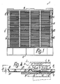
- a stacking aid 1 consisting of a plurality of stacking members to be put together to form a stacking insert device, is intended for stacking electric hotplates 2 in a field grid both one behind the other and next to one another such that adjacent vertical stacking columns of the same size are formed.
- the stacking aid 1 is particularly suitable for those electric hotplates 2 which, in the manner indicated by dash-dotted lines in FIG. 4, each have a cast material or the like.
- the hotplate body 3 has a flange 5 protruding on the underside, offset inwards with respect to the outer periphery of the cooking surface 4, and inside the flange 5 or between this and an inner flange protruding less far down on the underside one or more spiral grooves into which one or more heating resistors 6 are pressed into a ceramic insulating compound.
- the underside of the region of the hotplate body located within the outer circumference 8 of the flange edge 5 pers 3 is with a profiled end cover 7 made of sheet metal or the like.
- a support ring 9 is placed close to the cooking surface 4, which is supported on an annular shoulder facing away from the cooking surface 4 and adjoining the flange 5 radially outwards and has an approximately U-shaped cross section with diverging U-legs can be such that the radially outer, outwardly inclined profile leg forms with its lower ring edge a supporting edge which lies radially outside the furthest outer circumference of the hotplate body 3 lying in the area of the cooking surface 4.
- the electric hotplate 2 in the assembled state, lies braced radially outside an installation opening on the upper side of a built-in plate, while the part of the hotplate 2 underneath protrudes beyond the underside of the built-in plate.
- a number of separate, preferably substantially identical pallet plates 10 equal to the number of stacking layers or stacking layers is provided for packaging-like stacking of a plurality of electric hotplates 2 such that all the hotplates 2 of the respective stacking position are directly and positively secured against one another.
- a pressure-elastic insert 11 from in a relaxed state stood about 3 to 4 mm thick in the form of a foam mat made of plastic, so that direct contact of the respective pallet plate 10 with these cooking surfaces 4 is completely excluded, but on the other hand there is a support with a very high coefficient of friction and with a high surface protection. Stacked layers lying one above the other can therefore only be secured against one another by friction.
- the support pallet 2 consists essentially of a plate-shaped support grate provided on the top, which is arranged on support beams lying on the bottom and connected to one another on their underside with frame slats or a further support grate such that gaps between the support beams for the engagement of a forklift, for tensioning straps or the like remain free.
- the lowest pallet plate 10 is not directly on the supporting pallet 12, but there is a pressure-elastic intermediate layer in between, which is expediently formed by the bottom of the cardboard box 14 of a packaging sleeve 13, the clear width of which is almost equal to the outline of the pallet plates 10, so that the Pallet 12 protrudes slightly on all sides over the packaging sleeve 13.
- the cardboard box 14 which extends approximately over the entire height of the stack or by approximately two stack layers less, is closed at the top with a cardboard packaging lid 15 which closely overlaps its upper edge on the outside, the top wall of which, optionally with the interposition of an insert 11, directly on the overhead sides of the electric hot plates 2 formed by the cooking surfaces 4 in the illustrated case uppermost stack position is supported such that it can be tightened downwards without bumping against the cardboard box 14.
- a clamping plate 16 in the form of a roughly the same basic shape as the packaging lid 15 having slatted frame so large that one slat extends over all stacking columns in a row and thus each of these rows over such a slat can be clamped down against the support pallet 12 with compression of the inserts 11.
- the stack layers 18 of the stack 17 can be secured against one another so immovably that even high transverse loads such as z.ß. can occur during the emergency braking of a transport vehicle, do not lead to transverse displacements within the stack 17.
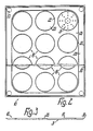
- Each pallet plate 10 has the same number of deep-drawn, identical or identical flat shells 19 as the number of stacking columns or hotplates 2 per stack position, which are arranged at equal intervals next to and behind one another in a rectangular row and column grid such that the outermost flat shells 19 are each provided at a distance from the adjacent outer edge of the pallet plate 10 that is at least as large or larger than the intermediate distance between adjacent flat shells 19.
- Each flat shell 19 has an essentially flat, thin-walled shell base 20 which is parallel to the plate plane of the pallet plate 10 and which on the outer circumference merges in one piece into a frustoconical shell shell 22 which diverges at an acute angle to the shell opening 23 at an angle of more than 45 ° or approximately 60 ° .
- the outer sides of the shell bottoms 20 of all the flat shells 19 of the respective pallet plate 10 facing away from the shell openings 23 form their only support surface 21 for support with respect to the adjacent stack position.
- the inner height 24 of the flat shells 19, which plus the thickness or wall thickness of the shell bottom 20 is equal to the total height or thickness of the pallet plate 10, is significantly less than that of the one with less than 15 or 10 mm, for example about 6 mm Supporting edge of the support ring 9 to the bottom to be measured installation depth 25 of the electric hotplates 2, namely at most half as large or smaller.
- the greatest inside width of the pan base 20 or the smallest inside width of the shell jacket 22 following this is at most slightly larger than the outside width of the hotplate 2 determined by the circumference 8 of the flange edge 5 in the region of its underside, so that the outside limitation of the pan bottom 20 is approximately congruent with the outer boundary of the flange 5 and the end cover 7.
- each pallet plate 10 lie in a flat, central plate field 26 which is continuous over all flat shells 19 and has essentially straight outer boundaries which are at a smaller distance from the outer flat shells 19 than their intermediate distances and in the area of the corners of the plate field lying flat shell 19 merge into each other via quarter-circular transition sections which are curved around the central axis of the respectively associated flat shell or follow the outer boundary thereof at a constant distance.
- the shell openings 23 lie in the plane of this plate field 26, such that the pallet plate 10 has no parts which protrude beyond the side of the plate field 26 facing away from the shell bottoms 20.
- a channel 28 is provided which continuously surrounds it on all sides, the channel bottom 29 of which lies in the plane of the tray bottom 20 and the channel flanks of which also lie on the same side as the tray openings 23 at the same angle as the tray jackets 22 diverge.
- the inner flank flank merges directly into the plate field 26 and forms its outer boundary.
- the outer, equally high channel flank forms a peripheral edge 27 which merges in the plane of the shell openings 23 or the channel opening into an outwardly directed edge flange 30, the width of which is substantially smaller than the channel depth and which determines the outer boundary of the pallet plate 10 with its edge .
- the pallet plate 10 has two substantially flat and mutually parallel outer sides, one of which is formed by the outer sides of the shell bottoms 20 and the channel bottom 29, while the other is formed by the side facing away from the flat shells 19 and the shell openings 23 perforated plate field 26 and the edge flange 30 is formed.
- a slip protection 31 is provided, as already explained, which on the one hand by the insert 11 and on the other hand by roughening, profiling, projections, such as spherical cap-shaped knobs 32 or the like. is formed, which protrude slightly beyond the outside of the respective associated tray bottom facing away from the inside of the tray, in particular by less than the height 24 of the pallet plate 10 or at most by a few millimeters.
- the knobs 32 which are expediently projecting by less than 3 mm or even by less than the wall thickness of the pallet plate 10, are embossed out of the respective shell base 20, so that they form corresponding depressions on the inside thereof.
- the knobs 32 are expediently arranged in concentric rings, the outermost of which is at a distance within the standing area of the hotplate 2 determined by the flange edge 5, while the innermost can be adapted to the inner width of the central recess in the cooking area 4 of the hotplate 2, that he intervenes in this as a centering and thus a kind of positive cross-securing stacking layers lying one above the other can be achieved.
- the total height of the stack 17 is only slightly higher than the sum of the height extensions of the superimposed electric hot plates 2, namely only by the sum of the wall thicknesses of the pallet plates 10, for example 1.5 mm, plus that in the area of the knob-shaped ones Support surfaces 21 reduced to a fraction of a millimeter squeeze thickness of the inserts 11 larger.
- the pallet plates 10 can be made from flat plates made of a relatively pressure-resistant plastic in a one-piece form in the vacuum deep-drawing process and are advantageously made of polystyrene. After the manufacture and after removal from the stack, the pallet plates 10 can be put together to form a flat stack, immediately lying one inside the other.
- the basic shape of the inserts 11 is expediently at least as large as that of the plate field 26 or slightly larger, but smaller than the basic shape of the pallet plates 10, so that the inserts 11 do not protrude beyond their outer boundaries, but with their outer edges they provide protection for the outside Offer sides of the cooking surfaces 4 and the support rings 9 of the outer hot plates 2.
- Each electric hotplate 2 has for its electrical connection in the installed position or for its electrical connection with a manually operated switching device on its underside two or more, in particular four adjacent connecting members 33 in the form of parallel, pin-shaped plug-in members, which together form one Form connector.
- the connecting members 33 are formed by angled, straight legs or ends of connecting wires which pass through an insulating piece 34 which is fastened in the region of the bottom of a recess in the end cover 7 and which are attached to the inside of the end cover 7 with their associated ones inner, also angled legs by spot welding or the like. are directly connected to the protruding pins of the heating resistors 6.
- the connecting members 33 protrude from the insulating piece 34 in the direction of the outer circumference 8 of the flange edge 5, but are slightly set back in relation to this outer circumference 8 or in relation to the inner circumference of the flange edge 5 and thus in relation to the above-mentioned standing surface of the hotplate 2.
- the connecting members 33 lie over their entire length in the region of a recess formed in the underside of the end cover 7, the depth of which is at least as large as the cross-sectional width of the connecting members 33, so that they can be completely accommodated in the recess without having to stand over or To protrude underside of the hotplate 2.
- the connecting members 33 can be designed in the manner of resilient arms and project in the relaxed state over the underside or the standing surface of the associated electric hotplate 2.
- the connecting members 33 are then pressed into the recess by abutment on the associated shell bottom 20. As soon as the electric hotplate 2 is removed from the stack or the hotplate 2 and the pallet plate 10 receiving it in its flat shells 19 are lifted from one another, the connecting members 33 can automatically spring back over the underside of the hotplate 2, so that they are inclined these are easily accessible for mounting or connection.
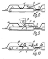
- the electric hot plates 2 are used for mounting in a mounting plate which is usually interspersed with three or four installation openings for receiving electric hot plates. According to FIGS. 5 to 10, a corresponding number of hot plates 2 are removed from at least one stack for assembly, the hot plates 2 generally being different and therefore being removed from a corresponding number of stacks, each with the same hot plates. are 1 and 4 are stacked, they are turned over after removal. If they are stacked upside down including the pallet plates, they do not need to be turned over.
- these hotplates 2 are placed in the spatial association given by the installation openings on an essentially flat supporting surface 40 with their cooking surfaces 4 and at the same time they are aligned with respect to their central axes perpendicular to the cooking surfaces 4 in such a way that their connecting members 33 or their Connectors are aligned in the desired predetermined position.
- This process is advantageously carried out fully automatically with at least one programmable handling device, which can have an electromagnet, for example, for holding or carrying the respective hotplate 2.
- the same or another programmable handling device or the like After placing the electric hot plates 2, the same or another programmable handling device or the like through a profiled sheet metal plate made of stainless steel.
- existing mounting plate 41 in the predetermined assignment so placed in the top position on the hot plates 2 that it receives these in their installation openings, which are usually provided in the region of elevations.
- the mounting plate 41 is loosely placed with its bottom upper side essentially exclusively only on the supporting edges of the supporting rings 9 of the electric hot plates 2.
- an intermediate part 45 consisting of a thicker steel sheet is placed fully automatically on the underside of the built-in plate 41 with the same or another programmable handling device, this profiled intermediate part 45 surrounding the hot plates 2 at a distance and not reaching to the outer limits of the built-in plate 41 .
- anti-rotation devices are created for the hotplates 2, which can be done in a simple manner together with the placement of the intermediate part 45, if this intermediate part 45 is made, for example, in one piece with it formed anti-rotation finger 46, each of which engages in a recess adjacent to the recess for the connecting members 33 in the end cover 7 of the hotplate 2 or in another counter member.
- a clamping part 42 which is also supported opposite the upper underside of the mounting plate 41 and is adjacent to its elevations around each electric hotplate 2, is formed, which in the area of each hotplate 2 forms a substantially flat-shell-shaped clamping shell covering its underside .
- the clamping part 42 is also placed fully automatically aligned with the same or another programmable handling device.
- a fastening bolt 47 in the form of, for example, a cap screw is inserted through a through opening in the bottom of each clamping shell and screwed into a threaded bore in the center pin 48 of the electric hotplate 2, the clamping shell being spring-loaded in this manner that on the one hand their edge rests on one side and the support ring 9 on the other side under resilient tension on the mounting plate 41.
- the bottom of the clamping shell can have a shape in the area of the fastening bolt 47, the end wall of which is braced against the end face of the central pin 48.
- Each clamping shell has in the area of the connecting members 33 of the associated electric hotplate 2 a window opening 49 which is continuous over part of its shell bottom and approximately over the entire height of its shell casing, through which the connecting members 33 remain accessible for connection. 8 is gripped through this window opening 49 with a lifter tool 50 and with this tool 50 the connecting members are bent by bending away from the top side of the electric hotplate 2 into the desired connection location transferred.
- the lifting tool 50 can be actuated fully automatically by the same or a separate handling device.
- a connector 43 is brought fully automatically through the window opening 49 to the connecting members 33 with the same or a separate handling device in such a way that its freely projecting connecting counter-members 51 come into engagement with the connecting members 33 and two of these members each lie in pairs next to each other, the inherently rigid but resiliently articulated connecting members 33 automatically aligning themselves with guide and threading surfaces which are provided on the counter members 51 or on an insulating body of the connecting piece 43 receiving them.
- the connector 43 is not designed for the plug connection, but for a spot weld connection with the connecting members 33.
- a multi-fine-point welding gun 52 is introduced to the pairs of connecting and counter-links fully automatically with a programmable handling device either through the window opening 49 or a separate, further window opening in the clamping shell, this welding gun 52 being one of the number of these pairs has a corresponding number of individual pliers.
- a transverse movement of the connecting piece 43 can ensure that the connecting and counter-members 33, 51 for the production of the welded connections already abut one another in a punctiform manner. All welded connections for all connecting members 33 are made simultaneously.
- the connecting counter-members 51 are electrically conductively connected to insulated, inherently rigid connecting lines 44 which connect to the connecting piece 43 or its insulating body on the side remote from the counter-members 51.
- the Connector 43 is then completely within the clamping shell, while the connecting lines 44 are led out through the window opening.
- the window opening 49 or the window openings can be covered with a cover or the like. are closed fully automatically except for the passage of the connecting lines 44 with the same or a separate handling device.
- Any existing earth connection, which can be fastened to the tensioning part 42, and a connection strain relief for the connection piece 42 can also be attached fully automatically using the same or a separate handling device.
- the mounting plate assembled in the manner described is removed from the assembly table or from the supporting surface 40 using the same or a separate programmable handling device and placed on a stack, so that a further assembly cycle can begin.
- the training according to the invention is not only for mounting plates made of sheet metal, but also for those made of tempered glass or the like. suitable, as described for example in DE-OS 33 17 624, which is referred to for further details and effects.
- the pallet plates 10 can have mutually alignable or stacked engagement members 53 in the form of holes, for example, which are provided outside the plate field 26 in the region of their corners in the channel bottom. These engagement members are suitable for the pallets, for example, by inserting rods that reach above the stack height plates 10 to align with each other. However, they can also serve as markings for a sensor of the handling device in order to detect the position of the stack. Furthermore, orientation aids for a search camera or a similar sensor can be attached to the four corners of the plate pallets or to their parts or regions of the stack, which pass on the information for alignment to the robot. These orientation aids are formed in particular by the links 53.
Landscapes
- Engineering & Computer Science (AREA)
- Mechanical Engineering (AREA)
- Chemical & Material Sciences (AREA)
- Combustion & Propulsion (AREA)
- General Engineering & Computer Science (AREA)
- Pallets (AREA)
- Automatic Analysis And Handling Materials Therefor (AREA)
- Cookers (AREA)
- Sampling And Sample Adjustment (AREA)
- Table Devices Or Equipment (AREA)
- Packages (AREA)
- Packaging Frangible Articles (AREA)
- Stacking Of Articles And Auxiliary Devices (AREA)
- Baking, Grill, Roasting (AREA)
Priority Applications (1)
| Application Number | Priority Date | Filing Date | Title |
|---|---|---|---|
| AT88113204T ATE88157T1 (de) | 1987-08-27 | 1988-08-13 | Kochplatten-stapelhilfe sowie verfahren zu deren verwendung. |
Applications Claiming Priority (2)
| Application Number | Priority Date | Filing Date | Title |
|---|---|---|---|
| DE19873728541 DE3728541A1 (de) | 1987-08-27 | 1987-08-27 | Kochplatten-stapelhilfe sowie verfahren zu deren verwendung |
| DE3728541 | 1987-08-27 |
Publications (2)
| Publication Number | Publication Date |
|---|---|
| EP0304752A1 true EP0304752A1 (fr) | 1989-03-01 |
| EP0304752B1 EP0304752B1 (fr) | 1993-04-14 |
Family
ID=6334567
Family Applications (1)
| Application Number | Title | Priority Date | Filing Date |
|---|---|---|---|
| EP88113204A Expired - Lifetime EP0304752B1 (fr) | 1987-08-27 | 1988-08-13 | Dispositif d'empilage pour réchauds et procédé pour son utilisation |
Country Status (9)
| Country | Link |
|---|---|
| US (1) | US4936457A (fr) |
| EP (1) | EP0304752B1 (fr) |
| JP (1) | JPS6481719A (fr) |
| AT (1) | ATE88157T1 (fr) |
| AU (1) | AU612688B2 (fr) |
| DE (2) | DE3728541A1 (fr) |
| ES (1) | ES2039524T3 (fr) |
| YU (1) | YU162488A (fr) |
| ZA (1) | ZA886229B (fr) |
Cited By (1)
| Publication number | Priority date | Publication date | Assignee | Title |
|---|---|---|---|---|
| WO2007033819A1 (fr) * | 2005-09-22 | 2007-03-29 | E.G.O. Elektro-Gerätebau GmbH | Plaque de cuisson electrique et disposition d'au moins une telle plaque de cuisson electrique dans une surface de travail |
Families Citing this family (7)
| Publication number | Priority date | Publication date | Assignee | Title |
|---|---|---|---|---|
| DE3803806A1 (de) * | 1988-02-09 | 1989-08-17 | Ego Elektro Blanc & Fischer | Elektrokochplatte |
| US6006577A (en) * | 1996-01-11 | 1999-12-28 | Daimlerchrysler Ag | Stackable drawn pieces and process and apparatus for manufacture thereof |
| DE19600755C1 (de) * | 1996-01-11 | 1997-04-10 | Daimler Benz Ag | Stapelbare Ziehteile, sowie ein Verfahren und eine Vorrichtung zur Herstellung derselben |
| US8530795B2 (en) | 2009-06-26 | 2013-09-10 | Evo, Inc. | Electric cooking apparatus |
| USD636630S1 (en) | 2010-06-25 | 2011-04-26 | Evo, Inc. | Electric cooking apparatus |
| CN111153016A (zh) * | 2019-12-18 | 2020-05-15 | 上海凌云工业科技有限公司凌云汽车技术分公司 | 一种用于电池壳体的物流仓储装置 |
| CN113636215B (zh) * | 2021-10-13 | 2021-12-24 | 常州金鹰医药包装有限公司 | 一种用于医药复合硬片的防压的运输包装设备 |
Citations (1)
| Publication number | Priority date | Publication date | Assignee | Title |
|---|---|---|---|---|
| EP0180752A1 (fr) * | 1984-10-31 | 1986-05-14 | E.G.O. Elektro-Geräte Blanc u. Fischer | Pièce d'empilage pour réchauds |
Family Cites Families (12)
| Publication number | Priority date | Publication date | Assignee | Title |
|---|---|---|---|---|
| US2662638A (en) * | 1949-08-18 | 1953-12-15 | Celanese Corp | Carton |
| US3008572A (en) * | 1960-03-10 | 1961-11-14 | Wayne Home Equipment Company | Oil burner shipping pallet |
| US3089589A (en) * | 1960-05-09 | 1963-05-14 | Crown Zellerbach Corp | Container |
| US3191791A (en) * | 1961-05-22 | 1965-06-29 | Expandolite Inc | Container |
| US3306439A (en) * | 1964-11-13 | 1967-02-28 | Celanese Corp | Cartons |
| DE6941014U (de) * | 1969-10-21 | 1970-04-09 | Knecht Filterwerke Ges Mit Bes | Ladepalette |
| US3904030A (en) * | 1973-05-10 | 1975-09-09 | Emerson Electric Co | Returnable packaging system |
| US4098400A (en) * | 1977-03-18 | 1978-07-04 | Emerson Electric Co. | Returnable packaging system |
| US4255626A (en) * | 1979-08-09 | 1981-03-10 | Guardian Electric Manufacturing Company | Multiple position switch |
| US4349109A (en) * | 1980-10-20 | 1982-09-14 | Medical Laboratory Automation, Inc. | Disposable pipette tips and trays therefor |
| CH641737A5 (fr) * | 1981-08-24 | 1984-03-15 | Stoco Sa | Palette de conditionnement pour pieces. |
| DE3509109A1 (de) * | 1985-03-14 | 1986-09-25 | Lauffenmühle GmbH & Co KG, 7890 Waldshut-Tiengen | Packzwischenlage fuer bewickelte textilspulen |
-
1987
- 1987-08-27 DE DE19873728541 patent/DE3728541A1/de not_active Withdrawn
-
1988
- 1988-08-13 AT AT88113204T patent/ATE88157T1/de not_active IP Right Cessation
- 1988-08-13 DE DE8888113204T patent/DE3880237D1/de not_active Expired - Fee Related
- 1988-08-13 EP EP88113204A patent/EP0304752B1/fr not_active Expired - Lifetime
- 1988-08-13 ES ES198888113204T patent/ES2039524T3/es not_active Expired - Lifetime
- 1988-08-23 ZA ZA886229A patent/ZA886229B/xx unknown
- 1988-08-23 US US07/235,431 patent/US4936457A/en not_active Expired - Fee Related
- 1988-08-25 YU YU01624/88A patent/YU162488A/xx unknown
- 1988-08-26 AU AU21584/88A patent/AU612688B2/en not_active Ceased
- 1988-08-26 JP JP63210886A patent/JPS6481719A/ja active Pending
Patent Citations (1)
| Publication number | Priority date | Publication date | Assignee | Title |
|---|---|---|---|---|
| EP0180752A1 (fr) * | 1984-10-31 | 1986-05-14 | E.G.O. Elektro-Geräte Blanc u. Fischer | Pièce d'empilage pour réchauds |
Cited By (1)
| Publication number | Priority date | Publication date | Assignee | Title |
|---|---|---|---|---|
| WO2007033819A1 (fr) * | 2005-09-22 | 2007-03-29 | E.G.O. Elektro-Gerätebau GmbH | Plaque de cuisson electrique et disposition d'au moins une telle plaque de cuisson electrique dans une surface de travail |
Also Published As
| Publication number | Publication date |
|---|---|
| DE3880237D1 (de) | 1993-05-19 |
| AU2158488A (en) | 1989-03-02 |
| US4936457A (en) | 1990-06-26 |
| DE3728541A1 (de) | 1989-03-09 |
| EP0304752B1 (fr) | 1993-04-14 |
| YU162488A (en) | 1990-12-31 |
| AU612688B2 (en) | 1991-07-18 |
| ZA886229B (en) | 1989-04-26 |
| JPS6481719A (en) | 1989-03-28 |
| ATE88157T1 (de) | 1993-04-15 |
| ES2039524T3 (es) | 1993-10-01 |
Similar Documents
| Publication | Publication Date | Title |
|---|---|---|
| EP0423656B1 (fr) | Dispositif pour verrouiller le couvercle d'une boîte, en particulier une boîte de peinture | |
| WO2020038511A1 (fr) | Récipient emboîtable isolé sous vide destiné au transport à température régulée de produits alimentaires | |
| EP2727854B1 (fr) | Dispositif d'orientation d'une pile de récipients | |
| EP0304752B1 (fr) | Dispositif d'empilage pour réchauds et procédé pour son utilisation | |
| EP2824035B1 (fr) | Dispositif de transport avec des récipients empilables | |
| DE3834067C2 (de) | Verfahren und Vorrichtung zur Herstellung eines mehrfächerigen Behälters | |
| DE1286813B (de) | Befestigungsvorrichtung fuer Schrauben | |
| DE3927502A1 (de) | Transportpalette | |
| DE2933349C2 (de) | Elektrokochplatte | |
| EP0338285A1 (fr) | Plaque de cuisson électrique | |
| EP0180752B1 (fr) | Pièce d'empilage pour réchauds | |
| EP0294781B1 (fr) | Dispositif pour assurer le couvercle d'une boîte, notamment boîte pour vernis | |
| DE69103078T2 (de) | Trägerelemente. | |
| DE202022103758U1 (de) | Verpackungssystem | |
| EP1929908B1 (fr) | Dispositif destiné à la préparation d'un produit alimentaire tempéré | |
| DE3934800A1 (de) | Stapeltransportkasten aus metallischem schichtmaterial | |
| DE102023121527B3 (de) | Stapelbares Backofenblech zum Backen von Teigwaren und ein Stapel mit einem ersten und zweiten derartigen Backofenblech | |
| DE3146676C2 (de) | Stapelbarer Deckel für Einwegbehälter aus Aluminiumfolie | |
| DE3405564C2 (de) | Transportvorrichtung | |
| DE3233180A1 (de) | Vorrichtung zum stapeln von flaschenkaesten | |
| DE9204593U1 (de) | Serviervorrichtung für eine Springform | |
| DE3423661A1 (de) | Kastenpalette | |
| AT412466B (de) | Stapelvorrichtung | |
| DE4000724A1 (de) | Vorrichtung zur verhinderung des verrutschens von transportkaesten auf paletten und aus diesen paletten und transportkaesten bestehender stapel | |
| DE102004012367A1 (de) | Behälter und Verfahren zum Herstellen eines Behälters |
Legal Events
| Date | Code | Title | Description |
|---|---|---|---|
| PUAI | Public reference made under article 153(3) epc to a published international application that has entered the european phase |
Free format text: ORIGINAL CODE: 0009012 |
|
| AK | Designated contracting states |
Kind code of ref document: A1 Designated state(s): AT CH DE ES FR GB GR IT LI SE |
|
| 17P | Request for examination filed |
Effective date: 19890525 |
|
| 17Q | First examination report despatched |
Effective date: 19910111 |
|
| GRAA | (expected) grant |
Free format text: ORIGINAL CODE: 0009210 |
|
| AK | Designated contracting states |
Kind code of ref document: B1 Designated state(s): AT CH DE ES FR GB GR IT LI SE |
|
| PG25 | Lapsed in a contracting state [announced via postgrant information from national office to epo] |
Ref country code: SE Effective date: 19930414 Ref country code: GR Free format text: LAPSE BECAUSE OF FAILURE TO SUBMIT A TRANSLATION OF THE DESCRIPTION OR TO PAY THE FEE WITHIN THE PRESCRIBED TIME-LIMIT Effective date: 19930414 Ref country code: GB Effective date: 19930414 Ref country code: FR Effective date: 19930414 |
|
| REF | Corresponds to: |
Ref document number: 88157 Country of ref document: AT Date of ref document: 19930415 Kind code of ref document: T |
|
| REF | Corresponds to: |
Ref document number: 3880237 Country of ref document: DE Date of ref document: 19930519 |
|
| ITF | It: translation for a ep patent filed | ||
| PG25 | Lapsed in a contracting state [announced via postgrant information from national office to epo] |
Ref country code: AT Effective date: 19930813 |
|
| PG25 | Lapsed in a contracting state [announced via postgrant information from national office to epo] |
Ref country code: LI Effective date: 19930831 Ref country code: CH Effective date: 19930831 |
|
| EN | Fr: translation not filed | ||
| REG | Reference to a national code |
Ref country code: ES Ref legal event code: FG2A Ref document number: 2039524 Country of ref document: ES Kind code of ref document: T3 |
|
| GBV | Gb: ep patent (uk) treated as always having been void in accordance with gb section 77(7)/1977 [no translation filed] |
Effective date: 19930414 |
|
| PLBE | No opposition filed within time limit |
Free format text: ORIGINAL CODE: 0009261 |
|
| STAA | Information on the status of an ep patent application or granted ep patent |
Free format text: STATUS: NO OPPOSITION FILED WITHIN TIME LIMIT |
|
| 26N | No opposition filed | ||
| REG | Reference to a national code |
Ref country code: CH Ref legal event code: PL |
|
| PGFP | Annual fee paid to national office [announced via postgrant information from national office to epo] |
Ref country code: ES Payment date: 19980814 Year of fee payment: 11 |
|
| PGFP | Annual fee paid to national office [announced via postgrant information from national office to epo] |
Ref country code: DE Payment date: 19981019 Year of fee payment: 11 |
|
| PG25 | Lapsed in a contracting state [announced via postgrant information from national office to epo] |
Ref country code: ES Free format text: LAPSE BECAUSE OF NON-PAYMENT OF DUE FEES Effective date: 19990814 |
|
| PG25 | Lapsed in a contracting state [announced via postgrant information from national office to epo] |
Ref country code: DE Free format text: LAPSE BECAUSE OF NON-PAYMENT OF DUE FEES Effective date: 20000601 |
|
| REG | Reference to a national code |
Ref country code: ES Ref legal event code: FD2A Effective date: 20000911 |
|
| PG25 | Lapsed in a contracting state [announced via postgrant information from national office to epo] |
Ref country code: IT Free format text: LAPSE BECAUSE OF NON-PAYMENT OF DUE FEES Effective date: 20050813 |