EP0304813A2 - Serielle Schnittstelle - Google Patents
Serielle Schnittstelle Download PDFInfo
- Publication number
- EP0304813A2 EP0304813A2 EP88113485A EP88113485A EP0304813A2 EP 0304813 A2 EP0304813 A2 EP 0304813A2 EP 88113485 A EP88113485 A EP 88113485A EP 88113485 A EP88113485 A EP 88113485A EP 0304813 A2 EP0304813 A2 EP 0304813A2
- Authority
- EP
- European Patent Office
- Prior art keywords
- control signals
- signal
- flip
- static
- circuit arrangement
- Prior art date
- Legal status (The legal status is an assumption and is not a legal conclusion. Google has not performed a legal analysis and makes no representation as to the accuracy of the status listed.)
- Granted
Links
Images
Classifications
-
- H—ELECTRICITY
- H04—ELECTRIC COMMUNICATION TECHNIQUE
- H04H—BROADCAST COMMUNICATION
- H04H40/00—Arrangements specially adapted for receiving broadcast information
- H04H40/18—Arrangements characterised by circuits or components specially adapted for receiving
- H04H40/27—Arrangements characterised by circuits or components specially adapted for receiving specially adapted for broadcast systems covered by groups H04H20/53 - H04H20/95
- H04H40/90—Arrangements characterised by circuits or components specially adapted for receiving specially adapted for broadcast systems covered by groups H04H20/53 - H04H20/95 specially adapted for satellite broadcast receiving
Definitions
- the invention relates to a circuit arrangement for evaluating control signals according to the preamble of claim 1.
- the invention has for its object to provide a circuit arrangement for evaluating control signals, which reliably separates the differently formed control signals and evaluates them for control purposes. This object is achieved in a circuit arrangement according to the preamble of claim 1 by the features specified in the characterizing part.
- static and dynamic control signals are static only over a relatively long period of time, but change their state when the command is changed, and this change can be confused with a dynamic state change.
- the dynamic changes in state behave like brief static changes, so that there is also a risk of confusion in this direction.
- the static states are first stored and the output of the memory is then used as a control signal. It is thereby achieved that a dynamic change of state has no influence on the can exercise the control signals obtained from the static control signals.
- the dynamic control signals are used to synchronize a flip-flop, so that this error is subsequently compensated for even in the event of incorrect synchronization by changing static control signals.
- the receiver for digital satellite broadcasting is intended to receive radio programs in accordance with the specifications of the radio transmission method in TV-SAT.
- the nesting of the programs in a frame structure and the accommodation of additional program information in special service frames and special service superframes, as well as in an additional information frame are described in DE-OS 33 080 25 or the technical guidelines ARD / ZDF No. 3R1 "Digital Satellite” Broadcasting (DSR) - Specifications of the radio transmission method in TV-SAT ", published by the IRT Institute for Broadcasting Technology, described in more detail.
- a special service bit and two additional information bits are transmitted in addition to the other data.
- Sixty-four main frames are combined in the special service bits to form a special service frame SA and in the additional information bits to form an additional information frame.
- part of the available data is reserved for scale factors and another part for program information PI.
- the program accompanying information PI relates to the programs whose samples have previously been transmitted.
- the number of available bits is not sufficient to be able to transmit program information for all channels in the additional information frame. Only in the case of stereo programs in which the program information is common to both channels is it possible to accommodate complete program information in an additional information frame. If, on the other hand, the channels are used individually, i.e.
- the program information is transmitted alternately for the mono channels, the assignment being defined in such a way that the program information for the left mono channel of the program begins when a special service frame begins 1 is transmitted. Depending on which mono channel is selected, each subsequent additional information frame of an odd number or every subsequent additional information frame of an even number must be evaluated after the start of the special service superframe.
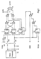
- a data processor 13 is shown, at one control output control signals M1 and at the other control output control signals M2 occur.
- the status of the static control signals M1S and M2S indicates which operating mode is present.
- the coding is chosen so that in stereo both outputs are on logic L, in two-tone broadcasts both outputs on logic H, in mono-left MIS on logic H and M2S on logic L and on mono right M1 on logic L and M2S on logic H.
- a dynamic signal M1D which briefly changes the state of M1, is output when it has been determined by the data processor that the synchronous word for the special service superframe has been correctly recognized.
- the signals are used to set a time window for program information in the "Mono" operating mode so that only the program information for the switched-on channel is evaluated and the others are suppressed.
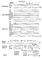
- FIG. 2 the signals being shown there on different stretched scales.
- the additional information frames as well as the special service frames each contain 64 bits.
- Eight special service frames result in a special service superframe, as shown in FIG. 2a.
- such signals are shown as continuous signals that occur regularly in the additional information frame.
- One is a signal G9, which appears during the duration of the ninth clock, and a signal G89N, which appears during the duration of the 18th and 19th clock.
- a window signal FE is also shown, through which the data containing the program accompanying information can be extracted from the data stream.
- the program accompanying information for the stereo programs is transmitted in each additional information frame. It is therefore permissible to evaluate the PI bits occurring during the duration of the signal FE in each additional information frame.
- control signals M1, M2 are at logic L, as a result of which both flip-flops 1, 2, via their outputs and the downstream NOR logic elements 3, 4, cause logic L at their outputs. Accordingly, the NAND gates 6, 7 are blocked and logically generate H. Das at the AND gate 8 Signal FE present at a third input is now switched through during each additional information frame.
- the “mono-left” operating mode is illustrated below the representation for stereo operation in FIG. 2d.
- the static control signals are correspondingly at M1 at logic H and M2 at logic L.
- the data processor After recognizing the synchronous word of the special service superframe SAÜ, the data processor briefly inverts the control signals and in this way emits a dynamic control signal M1D, which is used to select the window should continue to be used, in which the program information for the left mono channel is contained.
- the static control signals are present at the inputs of the flip-flop 1 and the flip-flop 2 before the event of the dynamic control signals M1D and are stored beforehand.
- a clock T32N, which is continuously present, and a signal G9, which is present in the additional information frame during the ninth bit, are used via the AND logic element 5 to be taken over into the memories.
- the corresponding pulse diagram is shown in FIG. 2e
Landscapes
- Physics & Mathematics (AREA)
- Astronomy & Astrophysics (AREA)
- General Physics & Mathematics (AREA)
- Engineering & Computer Science (AREA)
- Signal Processing (AREA)
- Manufacturing Of Electric Cables (AREA)
- Circuits Of Receivers In General (AREA)
- Time-Division Multiplex Systems (AREA)
- Synchronisation In Digital Transmission Systems (AREA)
- Testing, Inspecting, Measuring Of Stereoscopic Televisions And Televisions (AREA)
- Communication Control (AREA)
- Microcomputers (AREA)
- Debugging And Monitoring (AREA)
- Test And Diagnosis Of Digital Computers (AREA)
- Diaphragms For Electromechanical Transducers (AREA)
- Input Circuits Of Receivers And Coupling Of Receivers And Audio Equipment (AREA)
Abstract
- 1.1 Schaltungsanordnung zur Auswertung von Steuersignalen
- 2.1 Bei hochintegrierten Datenprozessoren ist die Anzahl der Steuerports beschränkt. Es besteht ein Problem darin, über die vorhandenen Steuerports unterschiedliche Steuersignale zuzuführen.
- 2.2 Bei einer Schaltungsanordnung zur Auswertung von aus einem Datenprozessor auf gegebenen Steuersignalen, die aus statischen und dynamischen Steuersignalen bestehen, ist ein Speicher vorgesehen, dem die statischen Steuersignale zugeführt sind, und ein weiterer Speicher, welcher durch das dynamische Signal synchronisiert wird.
- 2.3 Die Schaltungsanordnung ist bei der Verarbeitung von Steuersignalen in einem Empfänger für digitalen Audiorundfunk anwendbar.
Description
- Die Erfindung betrifft eine Schaltungsanordnung zur Auswertung von Steuersignalen nach dem Oberbegriff des Anspruchs 1.
- Bei hochintegrierten Datenprozessoren werden Einschränkungen bei der Herausführung von Steuer-Ports vorgenommen, um entweder genormte Gehäusegrößen verwenden zu können, oder aber die Ausmaße des Gehäuses und die Anzahl der Anschlußpins in Grenzen zu halten. Sind beispielsweise nur zwei Steuer-Ports vorhanden, so können mit statischen Steuersignalen lediglich 2² = 4 unterschiedliche Befehle erteilt werden. Um weitere Befehle ausgeben zu können, ist es möglich, dynamische Steuersignale zu verwenden, die den statischen überlagert werden.
- Der Erfindung liegt die Aufgabe zugrunde, eine Schaltungsanordnung zur Auswertung von Steuersignalen zu schaffen, die zuverlässig die unterschiedlich gebildeten Steuersignale trennt und für Steuerzwecke auswertet. Diese Aufgabe wird bei einer Schaltungsanordnung nach dem Oberbegriff des Anspruchs 1, durch die im kennzeichnenden Teil angegebenen Merkmale gelöst.
- Das besondere Problem bei der Auswertung von statischen und dynamischen Steuersignalen liegt darin, daß die statischen Steuersignale nur über einen verhältnismäßig langen Zeitraum statisch sind, bei Änderung des Befehls aber ihren Zustand ändern und diese Änderung mit einer dynamischen Zustandsänderung verwechselt werden kann. Umgekehrt verhalten sich die dynamischen Zustandsänderungen wie kurze statische, so daß auch in dieser Richtung eine Verwechselungsgefahr besteht. Bei der erfindungsgemäßen Schaltung werden die statischen Zustände zunächst gespeichert und der Ausgang des Speichers dann als Steuersignal verwendet. Dadurch wird erreicht, daß eine dynamische Zustandsänderung keinen Einfluß auf die aus den statischen Steuersignalen gewonnenen Steuersignale ausüben kann. Die dynamischen Steuersignale werden zur Synchronisation eines Flip-Flop benutzt, so daß auch bei einer Fehlsynchronisation durch Änderung statischer Steuersignale dieser Fehler anschließend ausgeglichen wird.
- Eine Weiterbildung sieht vor, eine Synchronisation nur innerhalb eines Zeitfensters zuzulassen, in welchem die dynamischen Steuersignale auftreten können, und vermeidet so eine Fehlsynchronisation. Zusätzliche Weiterbildungen und vorteilhafte Ausführungsformen der Erfindung ergeben sich aus den Ansprüchen, der Beschreibung und der Zeichnung, die ein Ausführungsbeispiel veranschaulicht.
- In der Zeichnung zeigen:
- Fig.1: Ein die Erfindung verkörperndes Schaltbild als Bestandteil eines Empfängers für digitalen Satelliten-Rundfunk,
- Fig.2 ein Impuls-Diagramm zur Erläuterung der in Fig.1 dargestellten Schaltung.
- Der Empfänger für digitalen Satelliten-Rundfunk ist dafür vorgesehen, Hörfunkprogramme nach den Spezifikationen des Hörfunk-Übertragunsverfahrens im TV-SAT zu empfangen. Die Verschachtelung der Programme in eine Rahmenstruktur und die Unterbringung zusätzlicher Programminformationen in Sonderdienst-Rahmen und Sonderdienst-Überrahmen, sowie in einem Zusatzinformations-Rahmen sind in der DE-OS 33 080 25 oder den technischen Richtlinien ARD/ZDF Nr. 3R1 "Digitaler Sateliten-Rundfunk (DSR) - Spezifikationen des Hörfunk-Übertragungsverfahrens im TV-SAT", herausgegeben vom IRT Institut für Rundfunktechnik, näher beschrieben.
- Im Hauptrahmen A nach den Spezifikationen wird neben den anderen Daten ein Sonderdienst-Bit, sowie zwei Zusatzinformations-Bit übertragen. Vierundsechzig Hauptrahmen werden bei den Sonderdienst-Bit zu einem Sonderdienst-Rahmen SA und bei den Zusatzinformations-Bit zu einem Zusatzinformations-Rahmen zusammengefaßt. In dem Zusatzinformations-Rahmen ist ein Teil der verfügbaren Daten für Skalen-Faktoren und ein anderer Teil für Programmbegleitinformationen PI reserviert. Die Programmbegleitinformationen PI beziehen sich auf die Programme, deren Abtastwerte zuvor übertragen werden. Die Anzahl der zur Verfügung stehenden Bit reicht jedoch nicht aus, um im Zusatzinformations-Rahmen für alle Kanäle Programminformationen übertragen zu können. Lediglich bei Stereo-Programmen, bei denen die Programminformationen für beide Kanäle gemeinsam sind, ist es möglich, vollständige Programminformationen in einem Zusatzinformations-Rahmen unterzubringen. Werden dagegen die Kanäle einzeln, also für Mono-Darbietungen genutzt, so werden die Programminformationen wechselweise für die Mono-Kanäle übertragen, wobei die Zuordnung so definiert ist, daß mit dem Beginn eines Sonderdienst-Überrahmens die Programminformation für den linken Mono-Kanal von Programm 1 übertragen wird. Je nach dem welcher Mono-Kanal gewählt ist, muß also nach dem Beginn des Sonderdienst-Überrahmens jeder folgende Zusatzinformations-Rahmen ungeradzahliger Ordnungszahl oder jeder folgende Zusatzinformations-Rahmen geradzahliger Ordnungszahl ausgewertet werden.
- In Fig. 1 ist ein Datenprozessor 13 dargestellt, an dessen einem Steuerausgang Steuersignale M1 und an dessem anderen Steuerausgang Steuersignale M2 auftreten. Durch den Zustand der statischen Steuersignale M1S und M2S wird angezeigt, welche Betriebsart vorliegt. Die Codierung ist so gewählt, daß bei Stereo beide Ausgänge auf logisch L sind, bei Zwei-Ton-Sendungen beide Ausgänge auf logisch H, bei Mono-links MIS auf logisch H und M2S auf logisch L und bei Mono-rechts M1 auf logisch L und M2S auf logisch H liegt. Ein dynamisches Signal M1D, das den Zustand von M1 kurzzeitig ändert, wird dann ausgegeben, wenn durch den Datenprozessor festgestellt wurde, daß das Synchronwort für den Sonderdienst-Überrahmen richtig erkannt worden ist. Die Signale werden dazu ausgenutzt, in der Betriebsart "Mono" ein Zeitfenster für Programm-Informationen so zu legen, daß nur die Programm-Informationen für den eingeschalteten Kanal ausgewertet und die anderen unterdrückt werden. Zur Erläuterung der Funktionsweise der in Fig. l dargestellten Schaltung wird zusätzlich auf Fig. 2 Bezug genommen, wobei die Signale dort in verschiedenen gedehnten Maßstäben dargestellt sind.
- Die Zusatzinformations-Rahmen, wie auch die Sonderdienst-Rahmen enthalten jeweils 64 Bit. Acht Sonderdienst-Rahmen ergeben, wie Fig. 2a zeigt, einen Sonderdienst-Überrahmen. In Fig. 2b sind als Dauersignale solche Signale dargestellt, die regelmäßig in dem Zusatzinformations-Rahmen vorkommen. Es handelt sich einmal um ein Signal G9, des während der Dauer des neunten Taktes erscheint, und um ein Signal G89N, das während der Dauer des 18. und 19. Taktes erscheint. Ferner ist ein Fenster-Signal FE dargestellt, durch das die die Programmbegleit-Informationen enthaltenen Daten aus dem Datenstrom ausgekoppelt werden können. Bei dem darunter dargestellten Betriebszustand "Stereo-Betrieb" in Fig. 2c werden die Programmbegleit-Informationen für die Stereo-Programme in jedem Zusatzinformations-Rahmen übermittelt. Es ist daher zulässig, in jedem Zusatzinformations-Rahmen die während der Dauer des Signals FE auftretenden PI-Bit auszuwerten. In diesem Falle liegen die Steuersignale Ml, M2 auf logisch L, wodurch beide Flip-Flops 1,2 über ihre Ausgänge und die nachgeschalteten NOR-Verknüpfungsglieder 3,4 logisch L an deren Ausgängen hervorrufen. Dementsprechend sind die NAND-Gatter 6,7 gesperrt und erzeugen an dem AND-Gatter 8 logisch H. Das an einem dritten Eingang anliegende Signal FE wird nun während jedes Zusatzinformations-Rahmens durchgeschaltet.
- Unterhalb der Darstellung für den Stereo-Betrieb ist in Fig. 2d die Betriebsart "Mono-links" veranschaulicht. Die statischen Steuersignale sind entsprechend bei M1 auf logisch H und M2 auf logisch L. Nach der Erkennung des Synchron-Wortes des Sonderdienst-Überrahmens SAÜ invertiert der Datenprozessor kurzzeitig die Steuersignale und gibt auf diese Weise ein dynamisches Steuersignal M1D ab, das zur Auswahl des Fensters weiterverwendet werde soll, in welchen die Programminformationen für den linken Mono-Kanal enthalten sind. Die statischen Steuersignale liegen an den Eingängen des FlipFlops 1 und des Flip-Flops 2 bereits vor dem Ereignis der dynamischen Steuersignale M1D an und werden zuvor gespeichert. Zur Übernahme in die Speicher wird einmal ein Takt T32N verwendet, der dauernd anliegt, und ein Signal G9, das während des neunten Bits im Zusatzinformations-Rahmen anliegt über das UND-Verknüpfungsglied 5 übernommen. Das entsprechende Pulsdiagramm zeigt Fig. 2e
- Zustandsänderungen an den Eingängen der Flip-Flops 1 und 2 bewirken während der übrigen Zeit im Zusatzinformations-Rahmen nun keine Änderung mehr. Bei Auftreten des dynamischen Signals M1D, das während des 18. oder 19. Bit im Zusatzinformations-Rahmen erwartet wird, vergl. hierzu die zeitlich gedehnte Darstellung in Fig. 2f, wird ein Flip-Flop 10 über einen hochfrequenten Takt T512N gesetzt, das über einen Ex-OR-Gatter 11 als Puls zu einem NOR-Gatter 12 gelangt und als Rücksetzsignal das Flip-Flop 9 zurücksetzt. Das entsprechende Pulsdiagramm zeigt Fig. 2g. Durch Verknüpfung des Ausgang Q des Flip-Flops 9 mit dem Ausgang des NORGatters 3 wird über ein NAND-Verknüpfungsglied 6 erreicht, daß das Gatter 8 nur während Zusatzinformations-Rahmen der Ordnungszahl 1 freigegeben wird. Das in einen definierten Zustand versetzte Flip-Flop 9 wird nämlich im nächsten Zusatzinformations-Rahmen durch T32N in dem Zeitintervall G9 umgeschaltet und führt durch Verknüpfung seines Ausgangssignals mit dem des NOR-Gliedes 3 zu einer Sperrung des NAND-Gliedes 8 und somit auch zu einer Sperrung des Fenstersignals FE. Erst wenn beim dritten Zusatzinformations-Rahmen wieder das Flip-Flop 9 in die ursprüngliche Lage schaltet, wird das AND-Gatter 8 freigegeben, sodaß das Signal FE durchgeschaltet und als Signal PIF weiterverarbeitet werden kann.
Claims (3)
Priority Applications (1)
| Application Number | Priority Date | Filing Date | Title |
|---|---|---|---|
| AT88113485T ATE96589T1 (de) | 1987-08-28 | 1988-08-19 | Serielle schnittstelle. |
Applications Claiming Priority (2)
| Application Number | Priority Date | Filing Date | Title |
|---|---|---|---|
| DE19873728793 DE3728793A1 (de) | 1987-08-28 | 1987-08-28 | Schaltungsanordnung zur auswertung von aus einem datenprozessor ausgegebene steuersignale |
| DE3728793 | 1987-08-28 |
Publications (3)
| Publication Number | Publication Date |
|---|---|
| EP0304813A2 true EP0304813A2 (de) | 1989-03-01 |
| EP0304813A3 EP0304813A3 (de) | 1991-04-10 |
| EP0304813B1 EP0304813B1 (de) | 1993-10-27 |
Family
ID=6334723
Family Applications (1)
| Application Number | Title | Priority Date | Filing Date |
|---|---|---|---|
| EP88113485A Expired - Lifetime EP0304813B1 (de) | 1987-08-28 | 1988-08-19 | Serielle Schnittstelle |
Country Status (5)
| Country | Link |
|---|---|
| EP (1) | EP0304813B1 (de) |
| JP (1) | JP2950834B2 (de) |
| AT (1) | ATE96589T1 (de) |
| DE (2) | DE3728793A1 (de) |
| HK (1) | HK124494A (de) |
Families Citing this family (11)
| Publication number | Priority date | Publication date | Assignee | Title |
|---|---|---|---|---|
| JP3076587B2 (ja) * | 1990-05-31 | 2000-08-14 | ナカミチ株式会社 | チェンジャー型ディスク再生装置 |
| JPH06259869A (ja) * | 1993-03-05 | 1994-09-16 | Nakamichi Corp | ディスク再生装置 |
| EP0614178A3 (de) * | 1993-03-05 | 1994-10-12 | Nakamichi Corp | Plattenspieler mit Compact-Disktransportvorrichtung. |
| JPH06259865A (ja) * | 1993-03-05 | 1994-09-16 | Nakamichi Corp | ディスク再生装置 |
| US5508994A (en) * | 1993-03-05 | 1996-04-16 | Nakamichi Corporation | Disk player with compact arrangement of a reader and disk storage magazine |
| JPH06259864A (ja) * | 1993-03-05 | 1994-09-16 | Nakamichi Corp | ディスク再生装置 |
| JP3183744B2 (ja) * | 1993-03-05 | 2001-07-09 | ナカミチ株式会社 | チェンジャ機能を備えたディスク再生装置 |
| JP2596255Y2 (ja) * | 1993-03-23 | 1999-06-07 | ナカミチ株式会社 | ディスク再生装置 |
| US5544148A (en) * | 1993-05-20 | 1996-08-06 | Nakamichi Corporation | Compact configuration disk player |
| JPH06349186A (ja) * | 1993-06-03 | 1994-12-22 | Nakamichi Corp | ディスク再生装置 |
| JP4741024B1 (ja) * | 2010-01-27 | 2011-08-03 | シャープ株式会社 | 画像形成装置 |
Family Cites Families (3)
| Publication number | Priority date | Publication date | Assignee | Title |
|---|---|---|---|---|
| JPS60117939A (ja) * | 1983-11-30 | 1985-06-25 | Matsushita Electric Works Ltd | 情報伝送方式 |
| SE458972B (sv) * | 1984-06-04 | 1989-05-22 | Yamatake Honeywell Co Ltd | Dialogfoerfarande samt anordning foer genomfoerande av foerfarandet |
| JPS6170827A (ja) * | 1984-09-14 | 1986-04-11 | Yamatake Honeywell Co Ltd | 通信装置 |
-
1987
- 1987-08-28 DE DE19873728793 patent/DE3728793A1/de not_active Withdrawn
-
1988
- 1988-08-19 EP EP88113485A patent/EP0304813B1/de not_active Expired - Lifetime
- 1988-08-19 DE DE88113485T patent/DE3885204D1/de not_active Expired - Fee Related
- 1988-08-19 AT AT88113485T patent/ATE96589T1/de active
- 1988-08-26 JP JP63210867A patent/JP2950834B2/ja not_active Expired - Fee Related
-
1994
- 1994-11-10 HK HK124494A patent/HK124494A/xx not_active IP Right Cessation
Also Published As
| Publication number | Publication date |
|---|---|
| HK124494A (en) | 1994-11-18 |
| JP2950834B2 (ja) | 1999-09-20 |
| EP0304813B1 (de) | 1993-10-27 |
| EP0304813A3 (de) | 1991-04-10 |
| DE3728793A1 (de) | 1989-03-09 |
| DE3885204D1 (de) | 1993-12-02 |
| ATE96589T1 (de) | 1993-11-15 |
| JPS6471338A (en) | 1989-03-16 |
Similar Documents
| Publication | Publication Date | Title |
|---|---|---|
| DE2011353C3 (de) | Verfahren zur Informationsübertragung und Informationsübertragungssystem zum Durchführen desselben | |
| DE3854292T2 (de) | Decoder. | |
| EP0304813B1 (de) | Serielle Schnittstelle | |
| DE3307781C2 (de) | Parallel-Serien-Datenwandler mit vorgebbarem Taktverhältnis | |
| DE3789042T2 (de) | Anordnung zum Detektieren von verschiedenartiger Mehrrahmensynchronisation auf einer digitalen Übertragungsleitung. | |
| DE2838104A1 (de) | Speicherkreis fuer einen tuner | |
| DE2726277A1 (de) | Abtastsignaldetektor | |
| DE69327443T2 (de) | Multiplexer, an dessen Eingang mehrere identische Signale verschiedener Phasenlage anliegen | |
| DE3335024A1 (de) | Schaltungsanordnung fuer einen empfaenger mit zwei phasenregelkreisen | |
| DE3743586C2 (de) | ||
| DE2752996A1 (de) | Digitale multiplexiervorrichtung fuer plesiochrone bitfolgen | |
| EP0079971A1 (de) | Digitalschaltung zur Abgabe eines Binärsignals beim Auftreten des Frequenzverhältnisses von Zeilen- und Bildfrequenz | |
| DE68913919T2 (de) | Hochfrequenz-Taktimpulszähler. | |
| DE2627713A1 (de) | Schaltungsanordnung zur feststellung der identitaet zwischen zwei bit-impulszuegen | |
| DE69113905T2 (de) | Rahmensynchronisierungseinrichtung mit einem seriell-zu-parallel-Umsetzer. | |
| DE3127493C2 (de) | Schaltungsanordnung zum Erzeugen eines Steuersignals für die Vertikalausgangsstufe in einem Fernsehempfänger | |
| DE3311896C2 (de) | ||
| EP0091061A2 (de) | Synchronisiereinrichtung einer Digitalsignal- Demultiplexeinrichtung | |
| DE2505388A1 (de) | Verfahren und anordnung zur logarithmischen umwandlung eines messwertes | |
| DE3688338T2 (de) | Am-stereo-empfaenger. | |
| DE2556486A1 (de) | Abstimmschaltung fuer hochfrequenzempfangsgeraete | |
| DE69110793T2 (de) | Zeitvielfachmultiplexiereinrichtung. | |
| DE1799029A1 (de) | Oszillografische schriftzeichenwiedergabevorrichtung | |
| DE3044968A1 (de) | Digital/analog-konverter, insbesondere fuer die verwendung in einem fernsehempfaenger | |
| DE2449984C2 (de) | Verriegelungsschaltung |
Legal Events
| Date | Code | Title | Description |
|---|---|---|---|
| PUAI | Public reference made under article 153(3) epc to a published international application that has entered the european phase |
Free format text: ORIGINAL CODE: 0009012 |
|
| AK | Designated contracting states |
Kind code of ref document: A2 Designated state(s): AT BE CH DE ES FR GB GR IT LI LU NL SE |
|
| PUAL | Search report despatched |
Free format text: ORIGINAL CODE: 0009013 |
|
| 17P | Request for examination filed |
Effective date: 19901231 |
|
| AK | Designated contracting states |
Kind code of ref document: A3 Designated state(s): AT BE CH DE ES FR GB GR IT LI LU NL SE |
|
| 17Q | First examination report despatched |
Effective date: 19921009 |
|
| GRAA | (expected) grant |
Free format text: ORIGINAL CODE: 0009210 |
|
| AK | Designated contracting states |
Kind code of ref document: B1 Designated state(s): AT BE CH DE ES FR GB GR IT LI LU NL SE |
|
| PG25 | Lapsed in a contracting state [announced via postgrant information from national office to epo] |
Ref country code: SE Effective date: 19931027 Ref country code: GR Free format text: LAPSE BECAUSE OF FAILURE TO SUBMIT A TRANSLATION OF THE DESCRIPTION OR TO PAY THE FEE WITHIN THE PRESCRIBED TIME-LIMIT Effective date: 19931027 Ref country code: ES Free format text: THE PATENT HAS BEEN ANNULLED BY A DECISION OF A NATIONAL AUTHORITY Effective date: 19931027 Ref country code: BE Effective date: 19931027 |
|
| REF | Corresponds to: |
Ref document number: 96589 Country of ref document: AT Date of ref document: 19931115 Kind code of ref document: T |
|
| ITF | It: translation for a ep patent filed | ||
| REF | Corresponds to: |
Ref document number: 3885204 Country of ref document: DE Date of ref document: 19931202 |
|
| GBT | Gb: translation of ep patent filed (gb section 77(6)(a)/1977) |
Effective date: 19931109 |
|
| ET | Fr: translation filed | ||
| PLBE | No opposition filed within time limit |
Free format text: ORIGINAL CODE: 0009261 |
|
| PG25 | Lapsed in a contracting state [announced via postgrant information from national office to epo] |
Ref country code: LU Free format text: LAPSE BECAUSE OF NON-PAYMENT OF DUE FEES Effective date: 19940831 |
|
| 26N | No opposition filed | ||
| REG | Reference to a national code |
Ref country code: GB Ref legal event code: 746 Effective date: 19970904 |
|
| PGFP | Annual fee paid to national office [announced via postgrant information from national office to epo] |
Ref country code: AT Payment date: 19980825 Year of fee payment: 11 |
|
| PGFP | Annual fee paid to national office [announced via postgrant information from national office to epo] |
Ref country code: CH Payment date: 19980826 Year of fee payment: 11 |
|
| PGFP | Annual fee paid to national office [announced via postgrant information from national office to epo] |
Ref country code: NL Payment date: 19980827 Year of fee payment: 11 |
|
| PG25 | Lapsed in a contracting state [announced via postgrant information from national office to epo] |
Ref country code: AT Free format text: LAPSE BECAUSE OF NON-PAYMENT OF DUE FEES Effective date: 19990819 |
|
| PG25 | Lapsed in a contracting state [announced via postgrant information from national office to epo] |
Ref country code: LI Free format text: LAPSE BECAUSE OF NON-PAYMENT OF DUE FEES Effective date: 19990831 Ref country code: CH Free format text: LAPSE BECAUSE OF NON-PAYMENT OF DUE FEES Effective date: 19990831 |
|
| PG25 | Lapsed in a contracting state [announced via postgrant information from national office to epo] |
Ref country code: NL Free format text: LAPSE BECAUSE OF NON-PAYMENT OF DUE FEES Effective date: 20000301 |
|
| REG | Reference to a national code |
Ref country code: CH Ref legal event code: PL |
|
| NLV4 | Nl: lapsed or anulled due to non-payment of the annual fee |
Effective date: 20000301 |
|
| REG | Reference to a national code |
Ref country code: FR Ref legal event code: D6 |
|
| REG | Reference to a national code |
Ref country code: GB Ref legal event code: IF02 |
|
| PGFP | Annual fee paid to national office [announced via postgrant information from national office to epo] |
Ref country code: GB Payment date: 20020624 Year of fee payment: 15 |
|
| PGFP | Annual fee paid to national office [announced via postgrant information from national office to epo] |
Ref country code: FR Payment date: 20020823 Year of fee payment: 15 |
|
| PGFP | Annual fee paid to national office [announced via postgrant information from national office to epo] |
Ref country code: DE Payment date: 20020904 Year of fee payment: 15 |
|
| PG25 | Lapsed in a contracting state [announced via postgrant information from national office to epo] |
Ref country code: GB Free format text: LAPSE BECAUSE OF NON-PAYMENT OF DUE FEES Effective date: 20030819 |
|
| PG25 | Lapsed in a contracting state [announced via postgrant information from national office to epo] |
Ref country code: DE Free format text: LAPSE BECAUSE OF NON-PAYMENT OF DUE FEES Effective date: 20040302 |
|
| GBPC | Gb: european patent ceased through non-payment of renewal fee |
Effective date: 20030819 |
|
| PG25 | Lapsed in a contracting state [announced via postgrant information from national office to epo] |
Ref country code: FR Free format text: LAPSE BECAUSE OF NON-PAYMENT OF DUE FEES Effective date: 20040430 |
|
| REG | Reference to a national code |
Ref country code: FR Ref legal event code: ST |
|
| PG25 | Lapsed in a contracting state [announced via postgrant information from national office to epo] |
Ref country code: IT Free format text: LAPSE BECAUSE OF NON-PAYMENT OF DUE FEES;WARNING: LAPSES OF ITALIAN PATENTS WITH EFFECTIVE DATE BEFORE 2007 MAY HAVE OCCURRED AT ANY TIME BEFORE 2007. THE CORRECT EFFECTIVE DATE MAY BE DIFFERENT FROM THE ONE RECORDED. Effective date: 20050819 |