EP0305017A2 - Récepteur de télévision comportant un dispositif de suppression de scintillement des lignes - Google Patents
Récepteur de télévision comportant un dispositif de suppression de scintillement des lignes Download PDFInfo
- Publication number
- EP0305017A2 EP0305017A2 EP88201819A EP88201819A EP0305017A2 EP 0305017 A2 EP0305017 A2 EP 0305017A2 EP 88201819 A EP88201819 A EP 88201819A EP 88201819 A EP88201819 A EP 88201819A EP 0305017 A2 EP0305017 A2 EP 0305017A2
- Authority
- EP
- European Patent Office
- Prior art keywords
- line
- picture
- intensity
- control unit
- light
- Prior art date
- Legal status (The legal status is an assumption and is not a legal conclusion. Google has not performed a legal analysis and makes no representation as to the accuracy of the status listed.)
- Granted
Links
Images
Classifications
-
- H—ELECTRICITY
- H04—ELECTRIC COMMUNICATION TECHNIQUE
- H04N—PICTORIAL COMMUNICATION, e.g. TELEVISION
- H04N7/00—Television systems
- H04N7/01—Conversion of standards, e.g. involving analogue television standards or digital television standards processed at pixel level
- H04N7/0127—Conversion of standards, e.g. involving analogue television standards or digital television standards processed at pixel level by changing the field or frame frequency of the incoming video signal, e.g. frame rate converter
- H04N7/0132—Conversion of standards, e.g. involving analogue television standards or digital television standards processed at pixel level by changing the field or frame frequency of the incoming video signal, e.g. frame rate converter the field or frame frequency of the incoming video signal being multiplied by a positive integer, e.g. for flicker reduction
Definitions
- the present invention relates to a television receiver having means for suppressing the so-called line flicker.
- TV pictures are transmitted and reproduced according to the interlace principle, whereby a whole picture consists of a number of lines and is composed of two half pictures, one of which is formed by the even numbered lines of the whole picture, while the other half picture comprises or is provided by the intermediate uneven line numbers.
- the two half pictures are reproduced in an alternating manner by a fast, successive scanning of the respective lines.
- the lines though disposed with small mutual spacing, are clearly recognizable on TV screens of usual sizes.
- the whole picture frequency is 50 or 60 Herz, and the discussed jumps of the transition line between light and dark in the two half pictures will thus take place with a frequency as low as 25 or 30 Herz. It is a widely used standard that the whole picture holds a total of 625 lines, and the eyes of a viewer, who is placed at a normal distance from a reasonably large screen, may well perceive disturbances when such a transition or border line carries out jumps of approximately 1/625 of the height of the screen. Another applied standard comprises only 525 lines.
- the line flicker problem is particular actual in pictures with text or graphics, and for some types of such reproductions, viz. so-called teletext or-graphics, it has already been suggested to solve the problem with the use of a correction signal that is supplied to the vertical deflector system so as to effect a displacement of one half picture into coincidence with the other half picture.
- a correction signal that is supplied to the vertical deflector system so as to effect a displacement of one half picture into coincidence with the other half picture.
- the said correction signal is derivable from a blanking signal which marks the cease of the original video signal and the start of the teletext signal.
- a technique which is described in DE-A-30 38 144 and 34 41 905, is not practically usable in connection with ordinary video pictures, where the vertical picture resolution would be unacceptably reduced.
- the invention is based on the recognition that the last mentioned prior proposal may be further developed so as to be successfully usable with ordinary video pictures, viz. by causing the line track on the screen to be locally displaced at such and only such place or places where dark/light transitions occur in the vertical direction, such that these transition places in the respective two half pictures will be brought closer to each other or be brought to fall together without the remaining picture details being treated in the same manner.
- the control signal to bring about such a displacement of a line or line portion in one or both half pictures is produceable based on a detection of the occurrence of the said abrupt dark/light transitions by detector means as described below.
- the line flicker can be counteracted purely locally, by a local displacement of a line or a portion of a line in one or both half pictures, and it is thus not necessary to give up the use of the interlacing principle nor the successive, time true reproduction of the half pictures, whereby a first result is that with this solution of the problem it is at least ensured that the solution is not transformed into new problems elsewhere on the screen.
- the solution according to the invention is usable also without giving rise to perceivable distortions of the reproduction at the critical places themselves, and that even additional advantages have been observed, i.e. the invention may be realized in a manner such that the problem is solved practically without disadvantageous side effects.
- a television receiver having means for suppression of line flicker, such means comprising a detector unit for detecting a potentially line flicker producing operation of the receiver and a control unit, which, in response to such a detection, is operable to produce a correction signal to the vertical deflector system of the picture reproducing unit of the receiver, by which the line track of the picture spot is disposed upwardly or downwardly to a location near or nearer the line level of the corresponding neighboring line in the preceding half picture,
- the detector unit is designed and arranged for continuous detection of the difference between the intensity of the actual video signal and the intensity of the video signal reproduction in a corresponding spot in at least one over- or underlying line in an interlace pattern on the screen, and in that the control unit is operable to produce the said control signal only in such situations in which it is detected by said detector unit that the picture spot is moved along a line portion forming a horizontal line of separation between over- and underlying picture areas of pronounced mutually different light intensity.
- the said local deformation or displacement of a line or a line portion on the screen of a traditional TV receiver is easily achievable by a modulation of the current to the vertical deflector coil for the cathode ray beam, which is sent against the inner side of the screen for describing or provideing the said lines by an associated horizontal deflection, or, respectively, by feeding a current to an additional vertical deflector coil, which will thereby weaken or strengthen the effect of the ordinary deflector coil, when corrections are to be made.
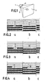
- the picture tube shown in Fig. 1 has a screen 2 which is hit by an electron beam from a beam gun 4, and a deflector coil 6 is provided for deflecting the beam in the vertical direction, while a deflector coil 8 is provided for deflecting the beam in the horizontal direction.
- These coils are controlled in a coordinated manner such that the beam is guided down along the screen at an even rate of velocity and is at the same time guided laterally one way and rapidly the other way for describing a number of horizontal lines on the screen, the beam being intensity modulated such that it will leave a light track with a varying intensity all according to the contents of the picture signal as received from the TV transmitter.
- the number of lines is 625, but other standards such as 525 and 1125 lines are known and used elsewhere.
- the picture signals of each whole picture are transmitted so as to divide the picture in two half pictures, of which the first is produced along the lines 1, 3, 5 etc., while the following half picture is produced along the intermediary lines 2, 4, 6 etc., whereby it is relevant to speak of an "interlaced" picture.
- the whole picture comprises a sharp horizontal separation between a light and a dark subarea, the associated line of separation cannot be located at the same place in the two half pictures, this being illustrated in Fig. 2.
- the first half picture is shown at 2a, and the single lines are designated A
- the following half picture is shown in Fig. 2b, in which the lines are designated B.
- FIG. 2c shows the next following half picture, which is here supposed to be identical with the first half picture according to Fig. 2a. It is illustrated that the lines in the respective half pictures are located so as to occupy the free spaces between each other; this is not fully representative of the reproduction on a usual picture screen, where passive separation lines occur between the lines of the whole picture, but these separation lines, which are normally dark, are of secondary importance for the invention, and the illustrations are more easily understood when these areas remain non-illustrated.
- the "empty" lines in each half picture are marked by a vertical hatching and are designated M. These lines are relatively dark.
- the line designated A is a light line, while the overlying line -A is also light and the underlying, i.e. subsequent line +A is a dark line; the line A is the lowermost line in an upper light picture area, while the line +A is the uppermost dark line in a lower, dark picture area.
- the line A is the line which is actually generated by the picture point, i.e. such that -A is the previously generated line and +A is the line which will be generated by the next line passage in the respective half picture.
- +B in Fig.2b designates the line in the following half picture corresponding to the line A, i.e. this line +B is reproduced with a delay of one half picture after the reproduction of the line A.
- +B is shown located in the empty line level just underneath the line A, but the respective "corresponding" line might as well be represented by the line -B.
- the lowermost light line in the upper, light picture area will jump an entire whole picture line up and down between the successive sive half pictures, and this is what amounts to line flicker. This phenomenon may be visible whenever a horizontal separation line exists between a light and a dark area, also while the picture is in a horizontal motion, i.e. by pannings and horizontally rolling texts.
- the detector signal is used to produce a parallel displacement of the relevant line in the half picture that is actually reproduced, viz. by affecting the vertical deflection control of the picture point in such a manner that the relevant line will be displaced towards or into coincidence with that line of the preceding half picture which constituted the light border line in the whole picture in the transition between the light and the dark picture area.
- Fig. 3a is identical with Fig. 2a
- Fig. 3b it is shown that the lower light line +B from Fig. 2b has been displaced up into the empty line just underneath the line -B, which is located in the same level as the line A in the preceding half picture.
- the thus displaced line, designated +B′ leaves an empty line Mb just underneath itself, but this line is naturally integrated with the lower dark picture area. What is important is that the lowermost light line +B′ or the line A, respectively, of the light picture area will be located in the same level in the two half pictures.
- Fig. 4 illustrates a dynamic course in which the picture point in a line A at one place changes from dark to light just above a dark picture area, the next half picture then being corrected by the immediately adjacent line +B at the same place first being corrected back from its previous, displaced B′-position down to its normal position, whereafter the following line in the same half picture will be lifted to its +B′-position immediately when the picture point changes from dark to light in the relevant +B′-line.
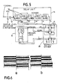
- FIG. 5 An example of a relevant detector is shown in Fig. 5.
- the received video signal is passed through a level detector 12 to a memory unit 14, which includes a row of delay units 16, which are operable, with the indicated delays, to produce respective intensity signals to a detector unit 18, which provides outlet signals to a control unit 20 for affecting the vertical deflector system 6 of the repro ducing device.
- the detector 18 is designed such that based on the received signals it will detect whether at the relevant place of the picture a vertical area exists in which a contrast transition is present between picture areas each consisting of two or more lines, the detector in such events being able to affect the control unit so as to produce the described displacement of the line upwardly or downwardly as required, such that the light border line is displaced from the dark area towards the light area for a non-jumping reproduction of the separation line.
- an outlet wire designated "1" from the control unit 18 will provide a signal to the control unit to the effect that the line displacement will amount to just a single line in the whole picture.
- a detected intensity jump will refer to the presence of a narrow light line consisting of a single light line in each half picture, and in that case there will be no criterion for orientating the displacement of the line from a dark towards a light area, though a line displacement up or down as required can still be employed.
- a better solution viz. to let the detector 18 be designed such that in such cases it will produce a particular "half line signal" represented by the outlet wire "1 ⁇ 2", this signal via the control unit 20 resulting in the respective lines of both the half pictures being displaced one half of a line width towards each other, whereby a merging of the two lines is obtained in the most natural way.
- Fig. 6 in which the jumping light line is illustrated in Fig. 6a, while the corrected, coinciding line in the two half pictures is shown in Fig. 6b.
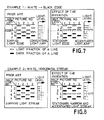
- Fig. 7 which is widely self explanatory, it is shown that the light intensity in a line shaped transition area with a conventional reproduction will be evenly increasing or decreasing across the jumping line area, while with the invention the light area in the transition area will show an increased intensity, just as the dark area will be still darker than the adjacent dark area. This may well amount to a distortion, but it has been found that visually it is rather a quite lucky one, inasfar as the transitions are marked with a high degree of clarity without seeming unnatural.
- screen flicker As well known there is another flicker phenomenon called screen flicker, which is caused by the fact that the picture frequency is as low as 50/60 Hz, whereby it is possible to visually realize that the picture is not fully steady. Nor strictlymally the screen flicker is perceived as still more disturbing than the line flicker as here being treated, and for this reason the invention will be particularly important when used in combination with means for eliminating the screen flicker. As already mentioned it is known to eliminate the line flicker by a doubling of the picture frequency, and this is also an efficient expedient for eliminating the screen flicker, though with the said associated problems with respect to a non-timetrue reproduction of one of the half pictures. There exists a still further method of eliminating the screen flicker, viz.
- the decision logic unit 18 should be adapted correspondingly in order to produce an optimal, graduated line displacement all according to the degree of contrast between the respective 'dark' and 'light' or rather 'darker' and 'lighter' picture details.
Landscapes
- Engineering & Computer Science (AREA)
- Multimedia (AREA)
- Signal Processing (AREA)
- Details Of Television Scanning (AREA)
- Two-Way Televisions, Distribution Of Moving Picture Or The Like (AREA)
- Picture Signal Circuits (AREA)
- Transforming Electric Information Into Light Information (AREA)
- Medicines Containing Antibodies Or Antigens For Use As Internal Diagnostic Agents (AREA)
- Heterocyclic Carbon Compounds Containing A Hetero Ring Having Oxygen Or Sulfur (AREA)
Priority Applications (1)
| Application Number | Priority Date | Filing Date | Title |
|---|---|---|---|
| AT88201819T ATE79207T1 (de) | 1987-08-26 | 1988-08-25 | Fernsehempfaenger mit unterdrueckung des zeilenflimmerns. |
Applications Claiming Priority (2)
| Application Number | Priority Date | Filing Date | Title |
|---|---|---|---|
| DK4444/87 | 1987-08-26 | ||
| DK444487A DK159354C (da) | 1987-08-26 | 1987-08-26 | Fjernsynsmodtager med midler til undertrykkelse aflinieflicker |
Publications (3)
| Publication Number | Publication Date |
|---|---|
| EP0305017A2 true EP0305017A2 (fr) | 1989-03-01 |
| EP0305017A3 EP0305017A3 (en) | 1989-08-23 |
| EP0305017B1 EP0305017B1 (fr) | 1992-08-05 |
Family
ID=8133576
Family Applications (1)
| Application Number | Title | Priority Date | Filing Date |
|---|---|---|---|
| EP88201819A Expired - Lifetime EP0305017B1 (fr) | 1987-08-26 | 1988-08-25 | Récepteur de télévision comportant un dispositif de suppression de scintillement des lignes |
Country Status (7)
| Country | Link |
|---|---|
| US (1) | US4888529A (fr) |
| EP (1) | EP0305017B1 (fr) |
| JP (1) | JPH01157674A (fr) |
| AT (1) | ATE79207T1 (fr) |
| DE (1) | DE3873449T2 (fr) |
| DK (1) | DK159354C (fr) |
| FI (1) | FI86588C (fr) |
Cited By (1)
| Publication number | Priority date | Publication date | Assignee | Title |
|---|---|---|---|---|
| EP0445336A1 (fr) * | 1990-03-09 | 1991-09-11 | Deutsche ITT Industries GmbH | Méthode et dispositif de réduction du scintillement du bord d'une image de télévision |
Families Citing this family (8)
| Publication number | Priority date | Publication date | Assignee | Title |
|---|---|---|---|---|
| ATE146026T1 (de) | 1990-09-14 | 1996-12-15 | Thomson Multimedia Sa | Verfahren und vorrichtung zur verbesserung vertikaler schärfe von bildröhren |
| US5627555A (en) * | 1993-04-14 | 1997-05-06 | Rca Thomson Licensing Corporation | Line flicker suppression by adaptive de-interlacing |
| US5936621A (en) * | 1996-06-28 | 1999-08-10 | Innovision Labs | System and method for reducing flicker on a display |
| US6130723A (en) * | 1998-01-15 | 2000-10-10 | Innovision Corporation | Method and system for improving image quality on an interlaced video display |
| ES2143883T3 (es) * | 1998-04-17 | 2000-05-16 | Barco Nv | Conversion de una señal de video para accionar una pantalla de cristal liquido. |
| US7119853B1 (en) | 1999-07-15 | 2006-10-10 | Sharp Laboratories Of America, Inc. | Method of eliminating flicker on an interlaced monitor |
| US20020167612A1 (en) * | 2001-04-02 | 2002-11-14 | Pelco | Device and method for reducing flicker in a video display |
| US7952545B2 (en) * | 2006-04-06 | 2011-05-31 | Lockheed Martin Corporation | Compensation for display device flicker |
Family Cites Families (2)
| Publication number | Priority date | Publication date | Assignee | Title |
|---|---|---|---|---|
| NL7901119A (nl) * | 1979-02-13 | 1980-08-15 | Philips Nv | Beeldweergeefinrichting voor het als een tweevoudig geinterlinieerd televisiebeeld weergeven van een door een beeldsignaalgenerator opgewekt tweewaardig signaal. |
| DE3441905A1 (de) * | 1984-11-16 | 1986-05-28 | Deutsche Thomson-Brandt Gmbh, 7730 Villingen-Schwenningen | Einrichtung zur beseitigung des zwischenzeilenflimmerns |
-
1987
- 1987-08-26 DK DK444487A patent/DK159354C/da not_active IP Right Cessation
-
1988
- 1988-08-24 FI FI883915A patent/FI86588C/fi not_active IP Right Cessation
- 1988-08-25 AT AT88201819T patent/ATE79207T1/de not_active IP Right Cessation
- 1988-08-25 EP EP88201819A patent/EP0305017B1/fr not_active Expired - Lifetime
- 1988-08-25 DE DE8888201819T patent/DE3873449T2/de not_active Expired - Fee Related
- 1988-08-26 US US07/236,722 patent/US4888529A/en not_active Expired - Fee Related
- 1988-08-26 JP JP63210884A patent/JPH01157674A/ja active Pending
Cited By (2)
| Publication number | Priority date | Publication date | Assignee | Title |
|---|---|---|---|---|
| EP0445336A1 (fr) * | 1990-03-09 | 1991-09-11 | Deutsche ITT Industries GmbH | Méthode et dispositif de réduction du scintillement du bord d'une image de télévision |
| US5146329A (en) * | 1990-03-09 | 1992-09-08 | Deutsche Itt Industries Gmbh | Apparatus and method for reducing line flicker in a television picture |
Also Published As
| Publication number | Publication date |
|---|---|
| FI86588B (fi) | 1992-05-29 |
| JPH01157674A (ja) | 1989-06-20 |
| ATE79207T1 (de) | 1992-08-15 |
| FI86588C (fi) | 1992-09-10 |
| DK444487D0 (da) | 1987-08-26 |
| FI883915A0 (fi) | 1988-08-24 |
| US4888529A (en) | 1989-12-19 |
| DK159354C (da) | 1991-03-11 |
| DK159354B (da) | 1990-10-01 |
| DE3873449D1 (de) | 1992-09-10 |
| EP0305017B1 (fr) | 1992-08-05 |
| DE3873449T2 (de) | 1993-03-25 |
| DK444487A (da) | 1989-02-27 |
| FI883915A7 (fi) | 1989-02-27 |
| EP0305017A3 (en) | 1989-08-23 |
Similar Documents
| Publication | Publication Date | Title |
|---|---|---|
| US6621927B1 (en) | Apparatus for detecting position of featuring region of picture, such as subtitle or imageless part | |
| US5546131A (en) | Television receiver having an arrangement for vertically shifting subtitles | |
| US4947251A (en) | Suppression of flicker effects in a television receiver | |
| EP0305017B1 (fr) | Récepteur de télévision comportant un dispositif de suppression de scintillement des lignes | |
| US5748257A (en) | Picture information detecting apparatus for a video signal | |
| WO1991003131A2 (fr) | Systeme de commande de convergence pour formats verticaux multiples | |
| US20050157171A1 (en) | Reducing burn-in associated with mismatched video image/display aspect ratios | |
| NL7901119A (nl) | Beeldweergeefinrichting voor het als een tweevoudig geinterlinieerd televisiebeeld weergeven van een door een beeldsignaalgenerator opgewekt tweewaardig signaal. | |
| EP0472572A1 (fr) | Transmission de donnees pendant la periode active de l'image. | |
| US5436669A (en) | Television display apparatus with adjustable vertical deflection waveform | |
| CN107666560B (zh) | 一种视频去隔行方法及装置 | |
| DE69731505T2 (de) | Fernsehempfänger | |
| US5166794A (en) | Drop out compensating circuit with interpolation of proximate pixel signals | |
| US5126843A (en) | Interpolation signal producing circuit with improved amplitude interpolation | |
| EP0939558A1 (fr) | Procès et appareil de correction en S dans une tube à rayons cathodiques | |
| EP0796007B1 (fr) | Circuit pour la synchronisation de lignes et d'image d'un signal vidéo numérisé | |
| KR100245539B1 (ko) | 보간신호형성회로 | |
| DE102006011010B3 (de) | Wiedergabeanordnung und Anzeigevorrichtung | |
| JP2834133B2 (ja) | テレビジョン方式 | |
| KR0130969Y1 (ko) | 텔레비전 화면의 수직확대시 확대율 보정장치 | |
| KR19990001251A (ko) | 영상화면의 확장처리시 수직사이즈 조정장치 | |
| KR19980071354A (ko) | 영상 신호 변환 장치 및 방법 | |
| WO2012089714A1 (fr) | Dispositif d'affichage stéréoscopique comprenant une unité de commande | |
| JPH05503163A (ja) | テレビ機器での偏向ラスタの位置を調整するための方法 | |
| JPS5890873A (ja) | テレビ受像機 |
Legal Events
| Date | Code | Title | Description |
|---|---|---|---|
| PUAI | Public reference made under article 153(3) epc to a published international application that has entered the european phase |
Free format text: ORIGINAL CODE: 0009012 |
|
| AK | Designated contracting states |
Kind code of ref document: A2 Designated state(s): AT BE CH DE ES FR GB GR IT LI NL SE |
|
| PUAL | Search report despatched |
Free format text: ORIGINAL CODE: 0009013 |
|
| AK | Designated contracting states |
Kind code of ref document: A3 Designated state(s): AT BE CH DE ES FR GB GR IT LI NL SE |
|
| 17P | Request for examination filed |
Effective date: 19900119 |
|
| 17Q | First examination report despatched |
Effective date: 19911128 |
|
| GRAA | (expected) grant |
Free format text: ORIGINAL CODE: 0009210 |
|
| AK | Designated contracting states |
Kind code of ref document: B1 Designated state(s): AT BE CH DE ES FR GB GR IT LI NL SE |
|
| PG25 | Lapsed in a contracting state [announced via postgrant information from national office to epo] |
Ref country code: IT Free format text: LAPSE BECAUSE OF FAILURE TO SUBMIT A TRANSLATION OF THE DESCRIPTION OR TO PAY THE FEE WITHIN THE PRE;WARNING: LAPSES OF ITALIAN PATENTS WITH EFFECTIVE DATE BEFORE 2007 MAY HAVE OCCURRED AT ANY TIME BEFORE 2007. THE CORRECT EFFECTIVE DATE MAY BE DIFFERENT FROM THE ONE RECORDED.SCRIBED TIME-LIMIT Effective date: 19920805 Ref country code: FR Effective date: 19920805 Ref country code: AT Effective date: 19920805 Ref country code: BE Effective date: 19920805 Ref country code: CH Effective date: 19920805 Ref country code: SE Free format text: THE PATENT HAS BEEN ANNULLED BY A DECISION OF A NATIONAL AUTHORITY Effective date: 19920805 Ref country code: NL Effective date: 19920805 Ref country code: LI Effective date: 19920805 Ref country code: GR Free format text: LAPSE BECAUSE OF FAILURE TO SUBMIT A TRANSLATION OF THE DESCRIPTION OR TO PAY THE FEE WITHIN THE PRESCRIBED TIME-LIMIT Effective date: 19920805 Ref country code: ES Free format text: THE PATENT HAS BEEN ANNULLED BY A DECISION OF A NATIONAL AUTHORITY Effective date: 19920805 |
|
| REF | Corresponds to: |
Ref document number: 79207 Country of ref document: AT Date of ref document: 19920815 Kind code of ref document: T |
|
| PGFP | Annual fee paid to national office [announced via postgrant information from national office to epo] |
Ref country code: GB Payment date: 19920811 Year of fee payment: 5 |
|
| REF | Corresponds to: |
Ref document number: 3873449 Country of ref document: DE Date of ref document: 19920910 |
|
| PGFP | Annual fee paid to national office [announced via postgrant information from national office to epo] |
Ref country code: DE Payment date: 19921006 Year of fee payment: 5 |
|
| REG | Reference to a national code |
Ref country code: CH Ref legal event code: PL |
|
| EN | Fr: translation not filed | ||
| NLV1 | Nl: lapsed or annulled due to failure to fulfill the requirements of art. 29p and 29m of the patents act | ||
| PLBE | No opposition filed within time limit |
Free format text: ORIGINAL CODE: 0009261 |
|
| STAA | Information on the status of an ep patent application or granted ep patent |
Free format text: STATUS: NO OPPOSITION FILED WITHIN TIME LIMIT |
|
| 26N | No opposition filed | ||
| PG25 | Lapsed in a contracting state [announced via postgrant information from national office to epo] |
Ref country code: GB Effective date: 19930825 |
|
| GBPC | Gb: european patent ceased through non-payment of renewal fee |
Effective date: 19930825 |
|
| PG25 | Lapsed in a contracting state [announced via postgrant information from national office to epo] |
Ref country code: DE Effective date: 19940503 |