EP0305542A1 - Cloison de separation mobile - Google Patents
Cloison de separation mobile Download PDFInfo
- Publication number
- EP0305542A1 EP0305542A1 EP88902546A EP88902546A EP0305542A1 EP 0305542 A1 EP0305542 A1 EP 0305542A1 EP 88902546 A EP88902546 A EP 88902546A EP 88902546 A EP88902546 A EP 88902546A EP 0305542 A1 EP0305542 A1 EP 0305542A1
- Authority
- EP
- European Patent Office
- Prior art keywords
- pillar
- connector
- panels
- tapered
- adjacent panels
- Prior art date
- Legal status (The legal status is an assumption and is not a legal conclusion. Google has not performed a legal analysis and makes no representation as to the accuracy of the status listed.)
- Granted
Links
Images


Classifications
-
- E—FIXED CONSTRUCTIONS
- E04—BUILDING
- E04B—GENERAL BUILDING CONSTRUCTIONS; WALLS, e.g. PARTITIONS; ROOFS; FLOORS; CEILINGS; INSULATION OR OTHER PROTECTION OF BUILDINGS
- E04B2/00—Walls, e.g. partitions, for buildings; Wall construction with regard to insulation; Connections specially adapted to walls
- E04B2/74—Removable non-load-bearing partitions; Partitions with a free upper edge
- E04B2/7407—Removable non-load-bearing partitions; Partitions with a free upper edge assembled using frames with infill panels or coverings only; made-up of panels and a support structure incorporating posts
- E04B2/7416—Removable non-load-bearing partitions; Partitions with a free upper edge assembled using frames with infill panels or coverings only; made-up of panels and a support structure incorporating posts with free upper edge, e.g. for use as office space dividers
- E04B2/7433—Removable non-load-bearing partitions; Partitions with a free upper edge assembled using frames with infill panels or coverings only; made-up of panels and a support structure incorporating posts with free upper edge, e.g. for use as office space dividers with panels and support posts
- E04B2/7437—Removable non-load-bearing partitions; Partitions with a free upper edge assembled using frames with infill panels or coverings only; made-up of panels and a support structure incorporating posts with free upper edge, e.g. for use as office space dividers with panels and support posts with panels hooked onto posts
-
- E—FIXED CONSTRUCTIONS
- E04—BUILDING
- E04B—GENERAL BUILDING CONSTRUCTIONS; WALLS, e.g. PARTITIONS; ROOFS; FLOORS; CEILINGS; INSULATION OR OTHER PROTECTION OF BUILDINGS
- E04B2/00—Walls, e.g. partitions, for buildings; Wall construction with regard to insulation; Connections specially adapted to walls
- E04B2/74—Removable non-load-bearing partitions; Partitions with a free upper edge
- E04B2/7407—Removable non-load-bearing partitions; Partitions with a free upper edge assembled using frames with infill panels or coverings only; made-up of panels and a support structure incorporating posts
- E04B2/7409—Removable non-load-bearing partitions; Partitions with a free upper edge assembled using frames with infill panels or coverings only; made-up of panels and a support structure incorporating posts special measures for sound or thermal insulation, including fire protection
-
- E—FIXED CONSTRUCTIONS
- E04—BUILDING
- E04B—GENERAL BUILDING CONSTRUCTIONS; WALLS, e.g. PARTITIONS; ROOFS; FLOORS; CEILINGS; INSULATION OR OTHER PROTECTION OF BUILDINGS
- E04B2/00—Walls, e.g. partitions, for buildings; Wall construction with regard to insulation; Connections specially adapted to walls
- E04B2/74—Removable non-load-bearing partitions; Partitions with a free upper edge
- E04B2/76—Removable non-load-bearing partitions; Partitions with a free upper edge with framework or posts of metal
- E04B2/78—Removable non-load-bearing partitions; Partitions with a free upper edge with framework or posts of metal characterised by special cross-section of the frame members as far as important for securing wall panels to a framework with or without the help of cover-strips
- E04B2/7809—Removable non-load-bearing partitions; Partitions with a free upper edge with framework or posts of metal characterised by special cross-section of the frame members as far as important for securing wall panels to a framework with or without the help of cover-strips of single or multiple tubular form
- E04B2/7818—Removable non-load-bearing partitions; Partitions with a free upper edge with framework or posts of metal characterised by special cross-section of the frame members as far as important for securing wall panels to a framework with or without the help of cover-strips of single or multiple tubular form of substantially rectangular form
-
- E—FIXED CONSTRUCTIONS
- E04—BUILDING
- E04B—GENERAL BUILDING CONSTRUCTIONS; WALLS, e.g. PARTITIONS; ROOFS; FLOORS; CEILINGS; INSULATION OR OTHER PROTECTION OF BUILDINGS
- E04B2/00—Walls, e.g. partitions, for buildings; Wall construction with regard to insulation; Connections specially adapted to walls
- E04B2/74—Removable non-load-bearing partitions; Partitions with a free upper edge
- E04B2002/7461—Details of connection of sheet panels to frame or posts
- E04B2002/7466—Details of connection of sheet panels to frame or posts using hooks
-
- E—FIXED CONSTRUCTIONS
- E04—BUILDING
- E04B—GENERAL BUILDING CONSTRUCTIONS; WALLS, e.g. PARTITIONS; ROOFS; FLOORS; CEILINGS; INSULATION OR OTHER PROTECTION OF BUILDINGS
- E04B2/00—Walls, e.g. partitions, for buildings; Wall construction with regard to insulation; Connections specially adapted to walls
- E04B2/74—Removable non-load-bearing partitions; Partitions with a free upper edge
- E04B2002/7461—Details of connection of sheet panels to frame or posts
- E04B2002/7468—Details of connection of sheet panels to frame or posts using magnets
-
- E—FIXED CONSTRUCTIONS
- E04—BUILDING
- E04B—GENERAL BUILDING CONSTRUCTIONS; WALLS, e.g. PARTITIONS; ROOFS; FLOORS; CEILINGS; INSULATION OR OTHER PROTECTION OF BUILDINGS
- E04B2/00—Walls, e.g. partitions, for buildings; Wall construction with regard to insulation; Connections specially adapted to walls
- E04B2/74—Removable non-load-bearing partitions; Partitions with a free upper edge
- E04B2002/7487—Partitions with slotted profiles
-
- E—FIXED CONSTRUCTIONS
- E04—BUILDING
- E04B—GENERAL BUILDING CONSTRUCTIONS; WALLS, e.g. PARTITIONS; ROOFS; FLOORS; CEILINGS; INSULATION OR OTHER PROTECTION OF BUILDINGS
- E04B2/00—Walls, e.g. partitions, for buildings; Wall construction with regard to insulation; Connections specially adapted to walls
- E04B2/74—Removable non-load-bearing partitions; Partitions with a free upper edge
- E04B2002/749—Partitions with screw-type jacks
Definitions
- This invention relates to a movable partition wall to be installed on a floor with its upper end being kept free, that is, a movable partition wall such as the one called a low partition wall used for simple and easy partitioning in an office room and the like.
- movable partition walls of this type there is one which comprises a panel provided at one connecting end thereof with an integrally formed pillar having connecting holes and at the other end thereof with connecting hooks bent downwardly, which engage the connecting holes in the pillar of an adjacent panel thereby to connect the two adjacent panels.
- a rectangular plate-like connector having a required bending strength may be.placed on the upper end surfaces of two adjacent panels, so that the opposite end portions of the connector may be fastened by bolts to the corresponding upper end surfaces of the panels.
- bolts mass-produced by forging are usually used with a resulting disadvantage.
- the bolts mass-produced by forging have adjacent their head a stem portion the diameter of which is substantially the same as the minor diameter of the threaded portion.
- the holes formed in the above-mentioned connector for a bolt to extend therethrough should have a diameter corresponding to the major diameter of the threaded portion of the bolt.
- This invention has been proposed in view of the above problems, and its object is to provide a movable partition wall in which adjacent panels can be accurately positioned and rigidly connected without sudden decrease of the connecting strength due to loosening of the fasteners, and without increase of the number of steps required for machining and assembling parts.
- Another object of the invention is to provide a movable partition wall which can connect pillars and panels securely by using connecting members and enhance the accuracy of assembly of the whole wall.
- the invention has adopted the following arrangements to attain the above-mentioned objects.
- the movable partition wall of the invention is characterized by the provision of a plurality of panels, a groove formed in the horizontal surface of each of adjacent panels and defined by the opposite tapered inner surfaces, a connector bridging the horizontal surfaces of the adjacent panels and having a tapered portion corresponding to the tapered surfaces of the above-mentioned groove fitted therein, and fasteners for securing the connector to the horizontal surfaces of the above-mentioned adjacent panels.
- the above-mentioned groove may be replaced by a ridge formed on the horizontal surface of each panel and having tapered outer surfaces, which are engaged by the tapered portion formed in the connector corresponding to the tapered surfaces of the ridge.
- a pillar may be or need not be interposed between adjacent panels.
- the number of the panels to be used is not limited to two, but three or four panels can also be used.
- a connector T-shaped in plane view is used, and where four panels are connected to form a cruciform shape, a connector cruciform in plane view is used.
- the manner of connecting two panels is not limited to a linear connection, but two panels may also be connected to form an L shape.
- the tapered portion of the connector engages the groove having opposite tapered inner surfaces or the ridge having opposite tapered outer surfaces.
- the panels are connected in a posture corrected by the connector with the fasteners providing a fastening force to produce a wedge effect in the connection between the tapered portion and the tapered surfaces. Therefore, such a movable partition wall is highly resistive to deformation caused by an external force acting in the direction of the thickness of the wall, so that a high ability of maintaining its contour can be obtained.
- each panel is provided with a groove formed in its upper end surface and defined by opposite tapered inner surfaces, with a connector bridging the upper end surfaces of adjacent panels and having a tapered portion corresponding to the above-mentioned tapered surfaces fitted into the above-mentioned groove, a nut supported adjacent the upper end of the above-mentioned pillar. and a bolt inserted through the middle portion of the above-mentioned connector to be screwed into the above-mentioned nut so that its fasten
- a ridge having tapered outer lateral surfaces may be provided on the upper end surface of the panel, and a tapered portion corresponding to the above-mentioned tapered surfaces may be formed on the connector so as to engage the ridge.
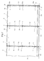
- the wall may be constructed in such a manner that with only the pillars at the opposite ends of the wall in contact with the floor, level adjustment is conducted, after which the adjusters provided on the bottom ends of the intermdeiate pillars are adjusted so as to bring the intermediate pillars into contact with the floor.
- the invention includes a concreate embodiment, wherein the panel comprises an upper frame component, side frame components and a bottom frame component, all made of aluminium and connected into a frame, with a pair of face plates made of a thin iron sheet being affixed to the opposite surfaces of the frame.
- each panel can not only be made light in weight and high in rigidity but also have the following effects.
- face plates made of a thin iron sheet were affixed to the opposite sides of an iron frame to form a panel, the surfaces of the face plates would be likely to be roughened. This is because metal particles are likely to be attached to the surfaces of the frame made of magnetic material such as iron due to residual magnetism and if the face plates were pressed and affixed to the frame with the iron particles remaining thereon, the face plates of a weaker, thin iron sheet would be deformed by the iron particles interposed therebetween.
- the frame components are made of aluminium, there is no such disadvantage that metallic particles are affixed to the surafces of the plates by residual magnetism, and that it is difficult to remove the affixed metallic particles.
- adhesive is previously applied to the surface of the frame, on which face plates are pressed with the adhesive in half-cured condition, the grains of the adhesive may constitute foreign bodies like the aforesaid affixed iron particles.
- the intervening grains of the adhesive are pushed into the aluminium frame having a lower hardness, so that the iron face plates will not be deformed.
- the frame components are made of aluminium and provided with a groove or a ridge having tapered surfaces, proper deformation of the frame components results in increased tightness of contact between the tapered surfaces and the tapered portion of the connector. As a result, the effect that the connection between the panels scarcely loosens can be obtained.
- the movable partition wall is provided with a pillar 1 having a right and a left contacting surface la, lb with connecting holes 2, and a panel 3 separate from the pillar 1 and having a right and a left contacting surface 3a, 3b with connecting hooks 4. so that the connecting hooks 4 engage the connecting holes 2, thereby to connect adjacent panels 3 to each other by the pillar 1.
- the pillar 1 is.made of a rectangular pipe having an adjuster 11 at its bottom end.
- Each of the right and left contacting surfaces la and lb of the pillar is formed with a plurality of connecting holes 2 vertically spaced a predetermined distance apart from each other.
- each connecting hole 2 is shaped like an inverted trapezoid the lower edge 21 of which is slightly shorter than the upper edge 22 thereof, and constitutes a through bore communicating the inside of the pillar 1 with the outside thereof.
- the panel 3 comprises an upper frame component 31, side frame components 32 and a lower frame component 34, all made of extruded aluminium and put together to form a frame, to each of the opposite surfaces of which a face plate 34 made of a thin iron sheet is adhered with epoxy adhesive or the like, with core members 35 enclosed therein.
- the right and left side frame components 32 comprise a rectangular tubular member having an outer surface la, lb to serve as a contacting surface of the panel 3, in which a wide outer groove 32a and a narrow inner groove 32b are formed, and the pillar 1 is fitted between the opposite inner lateral surfaces of the outer groove 32a as shown in Fig. 7.
- each connecting hook 4 is fixed in the above-mentioned inner groove 32b at those positions which correspond to the previously mentioned connecting holes 2.
- each connecting hook 4 comprises a base plate 41 secured to the bottom surface of the above-mentioned inner groove 32b and a pair of claws 42 extending outwardly from both side edges of the base plate 41.
- the above-mentioned claws 42 are of an inverted L shape and bent downwardly. The distance between the outer surfaces of the pair of claws 42 projecting from. each base plate 41 is set to the same length as the bottom edge 21 of the above-mentioned connecting hole 2.
- a connector 5 made of steel extends on the horizontal upper end surfaces 3c of adjacent panels 3, and the opposite end portions 5a of the connector 5 are secured to the upper frame components 31 of the corresponding panels 3 with a plurality of fasteners, say, two bolts 6, and a bolt 7 penetrating the middle of the connector 5 is screwed into a nut member 8 mounted adjacent the upper end of the above-mentioned pillar 1 thereby to pull the pillar 1 toward the connector 5.
- the connector 5 comprises a channel member U-shaped in cross section, and the middle portion of its bottom wall is protruded to assume a V-shaped contour, with the under surface of the protruded portion 51 being tapered as at 52.
- the upper surface of the upper frame component 31 of the above-mentioned panel 3 is formed with a groove 36 V-shaped in cross section.
- the inner surface of the groove 36 is tapered as at 37 in an upwardly diverging manner.
- a number of hook holes lc (not shown in Fig. 1) are formed in the middle portions of the front and rear surfaces of the pillar 1.
- the hook holes 1c are provided for the brackets for supporting shelf plates, desk top plates or the like to be detachably hooked therein, and are exposed in a joint 3d formed between adjacent panels 3.
- Upstanding edge portions 3e are formed along the front and rear edges of the upper end surface 3c of each panel 3, and an upper cover 91 engages the edge portions 3e so as to cover the upper end surface 3c of the panel.
- a side cover 92 is detachably mounted on the outer lateral side of the pillar 1 at the extreme end of the panel by the connecting claws 92a engaging the above-mentioned connecting holes 2.
- a connector 95 for connecting the panel 3 at the extreme end and the pillar 1 is shown in Fig. 10.
- the connector 95 is formed by cutting out one of the opposite end portions 5a of the above-mentioned connector 5, and is fastened to the above-mentioned panel 3 by bolts 6 and connected to the pillar 1 by a bolt 7.
- the plinth 93 is a plinth for covering the space between the lower end of each panel 3 and the floor surface 10.
- the plinth 93 is detachably fixed to the pillar 1 by engaging claws 93a with the above-mentioned hook holes 1c.
- the pillar 1 and the panel 3 may have a symmetrical shape. Therefore, these members can be used in a wider variety of manners compared with the conventional panels of asymmetric shapes. For example, panels of a single type having one surface differently colored from the other may be assembled into a wall of a desired color design by selectively using the differently colored surfaces of the component panels.
- the assembly error caused by insufficient engagement of the connecting claws 4 with the holes will not be accumulated by increase of the number of panels to be assembled.
- the pillar 1 is pulled toward the connector 5 by the fastening force of the bolt 7.
- the panel 3 having its upper surface 3c pressed down by the connector 5 is pushed downwardly relative to the pillar 1, so that the connecting claws 4 provided on the panel 3 engage the connecting holes 2 to the deepest position.
- each connecting claw 4 abut on or come very close to the bottom edge 21 of the above-mentioned connecting hole 2, thereby making it possible to decrease to the minimum the assembly error caused by insufficient engagement of the connecting claws 4 with the connecting holes 2.
- adjacent panels 3 can be tightly connected through the pillar 1 and the connector 5, so that the wall itself constructed by connecting a plurality of panels 3 becomes an integral body having a high rigidity.
- the connector 5 having a V-shaped tapered portion 52 is put into the tapered surfaces 37 of the V-shaped grooves 36 of adjacent panels 3, and both the reactive force which pulls the pillar 1 upwardly and the clamping force of the bolt 7 press the connector 5 against the above-mentioned panels 3, so that the adjacent panels 3 with the pillar 1 interposed therebetween are connected with their positions having been corrected by the wedge-like pressing action of the connector 5. Therefore, only if the above-mentioned connector 5 and the groove 36 of each panel 3 are formed straight, the surfaces of all panels 3 are made flush, so that the wall looks very well.
- a superior partition wall can be obtained, without appreciable offsetting of the surfaces of the component panels 3 from the wall surface even when, for example, light is projected onto the panels 3 at a small incident angle for indirect illumination.
- the ridged portion 5a of the above-mentioned connector 5 engages the groove 36 of each panel 3, with the opposite ends 5a of the connector 5 being fixed to the panels 3 by the bolts 6, a high strength of connection between the two panels is obtained, and the wall becomes highly resistive to deformation even when an external force is applied to the panel 3 in the direction of the thickness thereof.
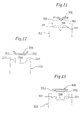
- the connector may take various cross-sectional shapes as shown, for example. in Figs. 11 through 17.
- the connector 105 shown in Fig. 11 is fabricated from a plate by bending the middle portion thereof into a V shape so as to provide a tapered portion 152, which is adapted to be brought into engagement with the tapered surfaces 137 of the groove 136 formed in the panel 103.
- the connector 205 shown in Fig. 12 is fabricated from a plate by bending the opposite edge portions thereof upwardly aslant, with the under surfaces of the bent portions . constituting a tapered portion 252, which is adapted to engage the tapered surfaces 237 of a groove 236 formed in the panel 203.
- the connector 405 shown in Fig. 14 is made of a thick iron plate which is provided in the bottom surface thereof with an inverted V-shaped groove having downwardly diverging tapered surfaces 452.
- a ridge 436 triangular in cross section is formed on the upper end surface 403c of the panel 403. The opposite outer lateral surfaces of the ridge 436 are formed into tapered surfaces 437, and the tapered portion 452 of the above-mentioned connector 405 engages the tapered surfaces 437 of the above-mentioned ridge 436.
- the connector 505 shown in Fig. 15 is also made of a thick iron plate which is provided in the bottom surface thereof with a trapezoidal groove having downwardly diverging tapered surfaces 552.
- a ridge 53 6 trapezoidal in cross section is formed on the upper end surface 503c of the panel 503.
- the opposite outer lateral surfaces of the ridge 536 are formed into tapered surfaces 537, and the tapered surfaces 552 of the above-mentioned connector 505 engage the tapered surfaces 537 of the above-mentioned ridge 536.
- the connector 605 shown in Fig. 16 is made of a sheet metal which is depressed in the middle portion thereof to provide a V-shaped groove defined by downwardly diverging tapered surfaces 652.
- a ridge 636 triangular in cross section is formed in the upper end surface 603c of the panel 603.
- the opposite outer lateral surfaces of the ridge 636 are formed into tapered surfaces 637, and the tapered portion 652 of the above-mentioned connector 605 engages the tapered surfaces 652 of the above-mentioned ridge 636.
- the connector 705 shown in Fig. 17 is fabricated from a sheet metal by bending the opposite lateral edge portions inwardly on the bottom surface thereof so as to form downwardly diverging tapered surfaces 752.
- a ridge 736 trapezoidal in cross section is provided on the upper end surface 703c of the panel 703.
- the opposite outer lateral surfaces of the ridge 736 are formed into tapered surfaces 737, and the tapered surfaces 752 of the above-mentioned connector 705 engage the tapered surfaces 752 of the above-mentioned ridge 736.
- Figs. 18 through 21 are schematic cross-sectional plane views showing different manners of connecting panels other than the above described linear connections between panels.
- the panels 803 are connected through a pillar 801 to form a connection L-shaped in plane view.
- the upper end surfaces of the two panels 803 are connected by a connector 805 L-shaped in plane view.
- the connector 805 has a shape similar in cross section to that of the connector used for linear connection.
- 809 is a decorative cover.
- the panels 903 abut on a pillar 901 in three directions for a connection T-shaped in plane view.
- the upper end surfaces of the panels 903 are connected by a connector 905 T-shaped in plane view.
- the connector 905 also has a shape similar in cross section to that of the connector used for linear connection.
- 909 is a decorative cover.
- the panels 1003 abut on a pillar 1001 in four directions for a connection cruciform in plane view.
- the upper edge surfaces of the panels 1003 are connected by a connector 1005 cruciform in plane view.
- the connector 1005 also has a shape similar in cross section to that of the connector used for linear connection.
- Fig. 21 is a sectional plane view showing an example in which the panels are connected linearly without using a pillar.
- the side frame component 1132 of the panel 1101 is generally L-shaped in plane view so that the side frame components 1132 of adjacent panels 1101 may mesh with each other.
- the horizontal surfaces of the two panels 1101 are connecte,d by a connector (not shown) similar to the connectors descirbed above.
- to connect the panels 1101 it is not necessary to insert a connecting bolt through the connecting member at the middle thereof so as to be screwed into the pillar, so that the connector need not be porvided with a central hole through which a bolt is to be inserted.
- the movable partition wall in accordance with the invention is useful as a partition wall for simple and easy partitioning in an office room or the like, and particularly suitable for supporting shelf plates, desk top plates or the like cantilevered on one side surface thereof.
Landscapes
- Engineering & Computer Science (AREA)
- Architecture (AREA)
- Physics & Mathematics (AREA)
- Electromagnetism (AREA)
- Civil Engineering (AREA)
- Structural Engineering (AREA)
- Joining Of Building Structures In Genera (AREA)
- Specific Sealing Or Ventilating Devices For Doors And Windows (AREA)
- Mutual Connection Of Rods And Tubes (AREA)
- Load-Bearing And Curtain Walls (AREA)
Abstract
Applications Claiming Priority (2)
| Application Number | Priority Date | Filing Date | Title |
|---|---|---|---|
| JP59222/87 | 1987-03-14 | ||
| JP62059222A JPH0684643B2 (ja) | 1987-03-14 | 1987-03-14 | 可動間仕切壁 |
Publications (3)
| Publication Number | Publication Date |
|---|---|
| EP0305542A1 true EP0305542A1 (fr) | 1989-03-08 |
| EP0305542A4 EP0305542A4 (fr) | 1989-04-24 |
| EP0305542B1 EP0305542B1 (fr) | 1993-06-02 |
Family
ID=13107135
Family Applications (1)
| Application Number | Title | Priority Date | Filing Date |
|---|---|---|---|
| EP88902546A Expired - Lifetime EP0305542B1 (fr) | 1987-03-14 | 1988-03-12 | Cloison de separation mobile |
Country Status (5)
| Country | Link |
|---|---|
| US (1) | US4914878A (fr) |
| EP (1) | EP0305542B1 (fr) |
| JP (1) | JPH0684643B2 (fr) |
| DE (1) | DE3881454T2 (fr) |
| WO (1) | WO1988007113A1 (fr) |
Cited By (6)
| Publication number | Priority date | Publication date | Assignee | Title |
|---|---|---|---|---|
| EP0458489A1 (fr) * | 1990-05-15 | 1991-11-27 | Westinghouse Electric Corporation | Système de division d'espace bureau |
| EP0458264A1 (fr) * | 1990-05-21 | 1991-11-27 | C.O.M. S. Coop. A R.L. | Procédé de fabrication pour systèmes d'ameublement de bureau et unité de bureau |
| FR2712323A1 (fr) * | 1993-11-08 | 1995-05-19 | Hoyez Sa | Système de cloisons amovibles à performances acoustiques et au feu perfectionnées. |
| EP0738804A1 (fr) * | 1995-04-11 | 1996-10-23 | Hoyez Sa | Système de cloisons amovibles à performances acoustiques et au feu perfectionnées |
| WO1997002391A1 (fr) * | 1995-07-04 | 1997-01-23 | Impirial Consulting S.A. | Systeme d'ancrage et de blocage pour un systeme de cloisons mobiles |
| WO1999007957A1 (fr) * | 1997-08-06 | 1999-02-18 | Mero Systeme Gmbh & Co. Kg | Cloison, notamment pour stands d'expositions |
Families Citing this family (54)
| Publication number | Priority date | Publication date | Assignee | Title |
|---|---|---|---|---|
| FR2640303B1 (fr) * | 1988-12-12 | 1991-03-29 | Lau Hansen Andre | Dispositif de montage de cloisons amovibles |
| US5251413A (en) * | 1990-01-19 | 1993-10-12 | Herman Miller, Inc. | Stabilized space dividing frames and panels |
| US5067294A (en) * | 1990-07-30 | 1991-11-26 | Mcgowan Bruce | Partition assembly |
| JP2778311B2 (ja) * | 1991-10-24 | 1998-07-23 | コクヨ株式会社 | 可動間仕切壁用連結部材 |
| US5377466A (en) * | 1992-05-29 | 1995-01-03 | Haworth, Inc. | Separable post/panel system |
| US5370249A (en) * | 1993-11-09 | 1994-12-06 | Russell-William, Ltd. | Display fixture assembly |
| US5784850A (en) * | 1994-11-10 | 1998-07-28 | Elderson; William L. | Stud wall system and method using spacer member |
| US6167665B1 (en) | 1996-06-07 | 2001-01-02 | Herman Miller, Inc. | Corner post for a wall panel system |
| US6223485B1 (en) | 1996-06-07 | 2001-05-01 | Herman Miller, Inc. | Wall panel system |
| US6000179A (en) * | 1996-12-13 | 1999-12-14 | Steelcase Inc. | Stacking panel and off-module panel connections |
| US5943834A (en) * | 1996-12-17 | 1999-08-31 | Steelcase Inc. | Partition construction |
| US6910306B2 (en) | 1996-12-24 | 2005-06-28 | Steelcase Development Corporation | Knock-down portable partition system |
| US5899035A (en) * | 1997-05-15 | 1999-05-04 | Steelcase, Inc. | Knock-down portable partition system |
| US6301846B1 (en) | 1996-12-24 | 2001-10-16 | Steelcase Development Inc. | Knock-down portable partition system |
| US6546684B2 (en) | 1998-04-15 | 2003-04-15 | Steelcase Development Corporation | Partition panel |
| US5867955B1 (en) * | 1997-07-14 | 2000-11-07 | Steelcase Inc | Panel-to-panel connectors for office partitions |
| US6223916B1 (en) * | 1998-07-03 | 2001-05-01 | Barry M. Enos | Shelving crossbar retainer and assembly and method for fixing a crossbar to a post |
| US6112485A (en) * | 1998-11-04 | 2000-09-05 | Haworth, Inc. | Post-panel connector arrangement |
| US6272803B1 (en) * | 1999-01-28 | 2001-08-14 | Steelcase Development Corporation | Connector system for in-line connection of freestanding partitions |
| US6708460B1 (en) | 1999-05-03 | 2004-03-23 | Dietrich Industries, Inc. | Stud wall system and method using a combined bridging and spacing device |
| CA2310548A1 (fr) | 1999-06-04 | 2000-12-04 | Herman Miller, Inc. | Systeme de panneaux muraux jointifs |
| GB2353541B (en) | 1999-06-04 | 2003-10-15 | Miller Herman Inc | Stackable wall panel system |
| US6920734B2 (en) | 2000-08-31 | 2005-07-26 | Dietrich Industries, Inc. | Bridging system for off-module studs |
| US6729085B2 (en) | 2001-02-09 | 2004-05-04 | Herman Miller, Inc. | Wall panel system |
| US6694695B2 (en) | 2001-08-27 | 2004-02-24 | Dietrich Industries, Inc. | Wall stud spacer system with spacer retainers |
| US6701689B2 (en) * | 2001-12-07 | 2004-03-09 | The Steel Network, Inc. | Stud spacer |
| US6684929B2 (en) | 2002-02-15 | 2004-02-03 | Steelcase Development Corporation | Panel system |
| US7017310B2 (en) * | 2003-03-06 | 2006-03-28 | Dietrich Industries, Inc. | Spacer bar retainers and methods for retaining spacer bars in metal wall studs |
| WO2004094739A2 (fr) * | 2003-04-17 | 2004-11-04 | Frank Mcdonald | Panneaux de batiment modulaire, leur procede d'assemblage et de fabrication |
| US20060096201A1 (en) * | 2004-11-05 | 2006-05-11 | Daudet Larry R | Building construction components |
| US20060096200A1 (en) * | 2004-11-05 | 2006-05-11 | Daudet Larry R | Building construction components |
| US20080189855A1 (en) * | 2007-02-09 | 2008-08-14 | Yu Zheng | Portable sleeping assembly |
| AT506281B1 (de) * | 2008-01-14 | 2010-05-15 | Alexander Doronin | Anordnung zur raumteilung |
| US7975445B2 (en) * | 2009-06-05 | 2011-07-12 | Inscape Corporation | Office partition system |
| US8646225B2 (en) | 2010-09-30 | 2014-02-11 | Jerry Wirtz | In-ground shelter |
| US20120222367A1 (en) * | 2011-03-03 | 2012-09-06 | Tornado Tech, LLC | Above-Ground Shelter and Method of Installing Same |
| US9109361B2 (en) | 2011-10-26 | 2015-08-18 | Simpson Strong-Tie Company, Inc. | Bracing bridging member |
| US8590255B2 (en) | 2011-10-26 | 2013-11-26 | Larry Randall Daudet | Bridging connector |
| US8528282B1 (en) * | 2012-02-20 | 2013-09-10 | Lemar Industries Corp. | Structural tube |
| US8887461B2 (en) * | 2013-02-19 | 2014-11-18 | Ctb Midwest, Inc. | Structural tube |
| JP5772664B2 (ja) * | 2012-03-02 | 2015-09-02 | 株式会社イトーキ | 間仕切装置におけるアジャスター装置 |
| USD684838S1 (en) | 2012-07-11 | 2013-06-25 | Jerry Wirtz | Handle adapted to be engaged with a latch |
| US11008753B2 (en) | 2013-03-13 | 2021-05-18 | Simpson Strong-Tie Company, Inc. | Corrugated bridging member |
| USD692746S1 (en) | 2013-03-13 | 2013-11-05 | Clarkwestern Dietrich Building Systems Llc | Bridging clip |
| US9849497B2 (en) | 2013-03-13 | 2017-12-26 | Simpson Strong-Tie Company Inc. | Teardrop and offset notch bridging connector |
| US9732520B2 (en) | 2013-03-17 | 2017-08-15 | Simpson Strong-Tie Company, Inc. | Inverted bridging connector |
| US9016024B1 (en) | 2013-11-27 | 2015-04-28 | Simpson Strong-Tie Company | Steel framing clip |
| USD732708S1 (en) | 2013-12-30 | 2015-06-23 | Simpson Strong-Tie Company | Flared joist and rafter connector |
| USD730545S1 (en) | 2013-12-30 | 2015-05-26 | Simpson Strong-Tie Company | Joist and rafter connector |
| US9091056B2 (en) | 2013-12-31 | 2015-07-28 | Simpson Strong-Tie Company, Inc. | Multipurpose concrete anchor clip |
| USD821851S1 (en) | 2017-02-24 | 2018-07-03 | Clarkwestern Dietrich Building Systems Llc | Bridging clip |
| USD823095S1 (en) | 2017-02-24 | 2018-07-17 | Clarkwestern Dietrich Building Systems Llc | Bridging clip with ribs |
| USD822455S1 (en) | 2017-02-24 | 2018-07-10 | Clarkwestern Dietrich Building Systems Llc | Bridging clip with a rib |
| US20180258636A1 (en) * | 2017-03-08 | 2018-09-13 | Paul Rahmanian | Configurable structures for firearm and tactical training |
Family Cites Families (26)
| Publication number | Priority date | Publication date | Assignee | Title |
|---|---|---|---|---|
| BE502387A (fr) * | ||||
| US3078968A (en) * | 1958-10-02 | 1963-02-26 | Harvey Aluminum Inc | Prefabricated partitioning |
| US3330084A (en) * | 1965-04-12 | 1967-07-11 | Lockheed Aircraft Corp | Wall panel joint cap construction |
| JPS5110572Y1 (fr) * | 1969-04-25 | 1976-03-22 | ||
| US3871153A (en) * | 1971-10-12 | 1975-03-18 | Jr Herbert L Birum | Partition device |
| JPS4854606U (fr) * | 1971-10-25 | 1973-07-13 | ||
| JPS4854606A (fr) * | 1971-11-12 | 1973-08-01 | ||
| US3766696A (en) * | 1972-02-04 | 1973-10-23 | Versa Wall Inc | Demountable wall partition system |
| JPS5110572A (ja) * | 1974-07-15 | 1976-01-28 | Takashi Matsura | Katamochishikinidanjidoshachushasochi |
| US4035972A (en) * | 1976-02-23 | 1977-07-19 | Jay Timmons | Panel joining arrangements |
| US4109430A (en) * | 1976-08-09 | 1978-08-29 | Ronald George Fuller | Demountable partition wall |
| US4104838A (en) * | 1977-05-17 | 1978-08-08 | Gf Business Equipment, Inc. | Portable wall assembly |
| US4120124A (en) * | 1977-06-21 | 1978-10-17 | Hon Industries Inc. | Movable wall assembly |
| US4250676A (en) * | 1978-09-19 | 1981-02-17 | Knoll International Inc. | Panel interconnecting and upholstery-retaining connection for a tubular frame |
| US4269005A (en) * | 1979-06-11 | 1981-05-26 | Hiebert, Inc. | Panel joining system |
| JPS634095Y2 (fr) * | 1980-11-25 | 1988-02-02 | ||
| US4424654A (en) * | 1981-08-11 | 1984-01-10 | Westinghouse Electric Corp. | Panel rigidizer |
| JPS5879614U (ja) * | 1981-11-26 | 1983-05-30 | 株式会社稲葉製作所 | パ−テイシヨン装置 |
| JPS601166B2 (ja) * | 1982-12-09 | 1985-01-12 | 株式会社 佐藤工業所 | コンクリ−ト型枠の脱型反転装置 |
| JPS59106914U (ja) * | 1982-12-31 | 1984-07-18 | 株式会社ニチベイ | 間仕切パネルの段違い連結装置 |
| US4601137A (en) * | 1983-07-29 | 1986-07-22 | The Tandem Group, Inc. | Locking mechanism for an office panel system |
| JPS6042810U (ja) * | 1983-09-02 | 1985-03-26 | 株式会社 天童木工 | パネル連結具 |
| US4567698A (en) * | 1983-12-13 | 1986-02-04 | Knoll International, Inc. | Space divider system |
| AU567401B2 (en) * | 1984-06-08 | 1987-11-19 | Westinghouse Electric Corporation | Panel rigidizing system |
| US4571907A (en) * | 1984-08-15 | 1986-02-25 | Herman Miller, Inc. | Frame connector system |
| JPS62149507U (fr) * | 1986-03-14 | 1987-09-21 |
-
1987
- 1987-03-14 JP JP62059222A patent/JPH0684643B2/ja not_active Expired - Lifetime
-
1988
- 1988-03-12 EP EP88902546A patent/EP0305542B1/fr not_active Expired - Lifetime
- 1988-03-12 WO PCT/JP1988/000261 patent/WO1988007113A1/fr not_active Ceased
- 1988-03-12 DE DE8888902546T patent/DE3881454T2/de not_active Expired - Lifetime
- 1988-03-12 US US07/296,049 patent/US4914878A/en not_active Expired - Lifetime
Cited By (7)
| Publication number | Priority date | Publication date | Assignee | Title |
|---|---|---|---|---|
| EP0458489A1 (fr) * | 1990-05-15 | 1991-11-27 | Westinghouse Electric Corporation | Système de division d'espace bureau |
| EP0458264A1 (fr) * | 1990-05-21 | 1991-11-27 | C.O.M. S. Coop. A R.L. | Procédé de fabrication pour systèmes d'ameublement de bureau et unité de bureau |
| US5287666A (en) * | 1990-05-21 | 1994-02-22 | C.O.M. S. Coop. A.R.L. | Office furnishing unit framework |
| FR2712323A1 (fr) * | 1993-11-08 | 1995-05-19 | Hoyez Sa | Système de cloisons amovibles à performances acoustiques et au feu perfectionnées. |
| EP0738804A1 (fr) * | 1995-04-11 | 1996-10-23 | Hoyez Sa | Système de cloisons amovibles à performances acoustiques et au feu perfectionnées |
| WO1997002391A1 (fr) * | 1995-07-04 | 1997-01-23 | Impirial Consulting S.A. | Systeme d'ancrage et de blocage pour un systeme de cloisons mobiles |
| WO1999007957A1 (fr) * | 1997-08-06 | 1999-02-18 | Mero Systeme Gmbh & Co. Kg | Cloison, notamment pour stands d'expositions |
Also Published As
| Publication number | Publication date |
|---|---|
| DE3881454T2 (de) | 1993-09-23 |
| WO1988007113A1 (fr) | 1988-09-22 |
| JPH0684643B2 (ja) | 1994-10-26 |
| US4914878A (en) | 1990-04-10 |
| DE3881454D1 (de) | 1993-07-08 |
| EP0305542B1 (fr) | 1993-06-02 |
| JPS63226432A (ja) | 1988-09-21 |
| EP0305542A4 (fr) | 1989-04-24 |
Similar Documents
| Publication | Publication Date | Title |
|---|---|---|
| US4914878A (en) | Movable partition wall | |
| US5768850A (en) | Method for erecting floor boards and a board assembly using the method | |
| US5467566A (en) | Curtain wall clip | |
| US5970675A (en) | Modular panel assembly | |
| US5653076A (en) | Method and system for assembling a wall | |
| GB2140670A (en) | Safety steel angle assembly rack | |
| US4575979A (en) | Bracket assembly for securing wall members | |
| US5769241A (en) | Screen panel fixing system | |
| GB1598134A (en) | Jointed structure components therefor and method of disassembly thereof | |
| US5732521A (en) | Longitudinal or transverse support for ceiling panelling | |
| US4513557A (en) | Clip for use with runner and runner assembly including the clip | |
| US4094114A (en) | Detachable wall mounting system | |
| CA2915184C (fr) | Fixation pour armoire de spa | |
| US5088154A (en) | Door hinge system | |
| JPH049366Y2 (fr) | ||
| US3973302A (en) | Clip for attaching header to I-beam | |
| JPH0621481B2 (ja) | 可動間仕切壁 | |
| JPH0621482B2 (ja) | 可動間仕切壁 | |
| KR200153981Y1 (ko) | 칸막이의 마감판 | |
| JPH0644962Y2 (ja) | パネル受爪の取付構造 | |
| CA1097423A (fr) | Dispositif de fixation a vis | |
| EP0323950B1 (fr) | Raccordement en équerre de profilés de faux plafonds et profilés utilisés à cet effet | |
| JPH0431421Y2 (fr) | ||
| JPH0827992A (ja) | 成形板の取付構造 | |
| NZ716393B2 (en) | Spa cabinet attachment |
Legal Events
| Date | Code | Title | Description |
|---|---|---|---|
| PUAI | Public reference made under article 153(3) epc to a published international application that has entered the european phase |
Free format text: ORIGINAL CODE: 0009012 |
|
| 17P | Request for examination filed |
Effective date: 19881109 |
|
| AK | Designated contracting states |
Kind code of ref document: A1 Designated state(s): BE CH DE FR GB IT LI NL |
|
| A4 | Supplementary search report drawn up and despatched |
Effective date: 19890424 |
|
| 17Q | First examination report despatched |
Effective date: 19901019 |
|
| GRAA | (expected) grant |
Free format text: ORIGINAL CODE: 0009210 |
|
| AK | Designated contracting states |
Kind code of ref document: B1 Designated state(s): BE CH DE FR GB IT LI NL |
|
| ITF | It: translation for a ep patent filed | ||
| REF | Corresponds to: |
Ref document number: 3881454 Country of ref document: DE Date of ref document: 19930708 |
|
| ET | Fr: translation filed | ||
| PLBE | No opposition filed within time limit |
Free format text: ORIGINAL CODE: 0009261 |
|
| STAA | Information on the status of an ep patent application or granted ep patent |
Free format text: STATUS: NO OPPOSITION FILED WITHIN TIME LIMIT |
|
| 26N | No opposition filed | ||
| REG | Reference to a national code |
Ref country code: GB Ref legal event code: IF02 |
|
| PG25 | Lapsed in a contracting state [announced via postgrant information from national office to epo] |
Ref country code: IT Free format text: LAPSE BECAUSE OF NON-PAYMENT OF DUE FEES;WARNING: LAPSES OF ITALIAN PATENTS WITH EFFECTIVE DATE BEFORE 2007 MAY HAVE OCCURRED AT ANY TIME BEFORE 2007. THE CORRECT EFFECTIVE DATE MAY BE DIFFERENT FROM THE ONE RECORDED. Effective date: 20050312 |
|
| PGFP | Annual fee paid to national office [announced via postgrant information from national office to epo] |
Ref country code: GB Payment date: 20070307 Year of fee payment: 20 |
|
| PGFP | Annual fee paid to national office [announced via postgrant information from national office to epo] |
Ref country code: DE Payment date: 20070308 Year of fee payment: 20 |
|
| PGFP | Annual fee paid to national office [announced via postgrant information from national office to epo] |
Ref country code: CH Payment date: 20070314 Year of fee payment: 20 |
|
| PGFP | Annual fee paid to national office [announced via postgrant information from national office to epo] |
Ref country code: NL Payment date: 20070315 Year of fee payment: 20 |
|
| PGFP | Annual fee paid to national office [announced via postgrant information from national office to epo] |
Ref country code: BE Payment date: 20070514 Year of fee payment: 20 |
|
| BE20 | Be: patent expired |
Owner name: *KOKUYO CO. LTD Effective date: 20080312 |
|
| REG | Reference to a national code |
Ref country code: GB Ref legal event code: PE20 Expiry date: 20080311 |
|
| REG | Reference to a national code |
Ref country code: CH Ref legal event code: PL |
|
| PG25 | Lapsed in a contracting state [announced via postgrant information from national office to epo] |
Ref country code: NL Free format text: LAPSE BECAUSE OF EXPIRATION OF PROTECTION Effective date: 20080312 |
|
| PGFP | Annual fee paid to national office [announced via postgrant information from national office to epo] |
Ref country code: FR Payment date: 20070308 Year of fee payment: 20 Ref country code: IT Payment date: 20070622 Year of fee payment: 20 |
|
| PGRI | Patent reinstated in contracting state [announced from national office to epo] |
Ref country code: IT Effective date: 20080301 |
|
| NLV7 | Nl: ceased due to reaching the maximum lifetime of a patent |
Effective date: 20080312 |
|
| PG25 | Lapsed in a contracting state [announced via postgrant information from national office to epo] |
Ref country code: GB Free format text: LAPSE BECAUSE OF EXPIRATION OF PROTECTION Effective date: 20080311 |