EP0305732A2 - Barre de guidage pour un joint d'angle - Google Patents
Barre de guidage pour un joint d'angle Download PDFInfo
- Publication number
- EP0305732A2 EP0305732A2 EP88112092A EP88112092A EP0305732A2 EP 0305732 A2 EP0305732 A2 EP 0305732A2 EP 88112092 A EP88112092 A EP 88112092A EP 88112092 A EP88112092 A EP 88112092A EP 0305732 A2 EP0305732 A2 EP 0305732A2
- Authority
- EP
- European Patent Office
- Prior art keywords
- faceplate
- hook
- corner connection
- support stop
- stop
- Prior art date
- Legal status (The legal status is an assumption and is not a legal conclusion. Google has not performed a legal analysis and makes no representation as to the accuracy of the status listed.)
- Withdrawn
Links
- 230000000149 penetrating effect Effects 0.000 claims description 2
- 238000011144 upstream manufacturing Methods 0.000 claims 1
- 210000002105 tongue Anatomy 0.000 description 11
- 238000010168 coupling process Methods 0.000 description 7
- 230000008878 coupling Effects 0.000 description 6
- 238000005859 coupling reaction Methods 0.000 description 6
- 230000003993 interaction Effects 0.000 description 2
- 229910000639 Spring steel Inorganic materials 0.000 description 1
- 229910000831 Steel Inorganic materials 0.000 description 1
- 238000011031 large-scale manufacturing process Methods 0.000 description 1
- 239000000463 material Substances 0.000 description 1
- 239000002184 metal Substances 0.000 description 1
- 239000007769 metal material Substances 0.000 description 1
- 239000010959 steel Substances 0.000 description 1
Images


Classifications
-
- E—FIXED CONSTRUCTIONS
- E05—LOCKS; KEYS; WINDOW OR DOOR FITTINGS; SAFES
- E05D—HINGES OR SUSPENSION DEVICES FOR DOORS, WINDOWS OR WINGS
- E05D15/00—Suspension arrangements for wings
- E05D15/48—Suspension arrangements for wings allowing alternative movements
- E05D15/52—Suspension arrangements for wings allowing alternative movements for opening about a vertical as well as a horizontal axis
- E05D15/5208—Suspension arrangements for wings allowing alternative movements for opening about a vertical as well as a horizontal axis with means for transmitting movements between vertical and horizontal sliding bars, rods or cables
-
- E—FIXED CONSTRUCTIONS
- E05—LOCKS; KEYS; WINDOW OR DOOR FITTINGS; SAFES
- E05C—BOLTS OR FASTENING DEVICES FOR WINGS, SPECIALLY FOR DOORS OR WINDOWS
- E05C9/00—Arrangements of simultaneously actuated bolts or other securing devices at well-separated positions on the same wing
- E05C9/004—Faceplates ; Fixing the faceplates to the wing
-
- E—FIXED CONSTRUCTIONS
- E05—LOCKS; KEYS; WINDOW OR DOOR FITTINGS; SAFES
- E05C—BOLTS OR FASTENING DEVICES FOR WINGS, SPECIALLY FOR DOORS OR WINDOWS
- E05C9/00—Arrangements of simultaneously actuated bolts or other securing devices at well-separated positions on the same wing
- E05C9/24—Means for transmitting movements between vertical and horizontal sliding bars, rods or cables for the fastening of wings, e.g. corner guides
-
- E—FIXED CONSTRUCTIONS
- E05—LOCKS; KEYS; WINDOW OR DOOR FITTINGS; SAFES
- E05F—DEVICES FOR MOVING WINGS INTO OPEN OR CLOSED POSITION; CHECKS FOR WINGS; WING FITTINGS NOT OTHERWISE PROVIDED FOR, CONCERNED WITH THE FUNCTIONING OF THE WING
- E05F7/00—Accessories for wings not provided for in other groups of this subclass
- E05F7/08—Means for transmitting movements between vertical and horizontal sliding bars, rods, or cables
-
- E—FIXED CONSTRUCTIONS
- E05—LOCKS; KEYS; WINDOW OR DOOR FITTINGS; SAFES
- E05Y—INDEXING SCHEME ASSOCIATED WITH SUBCLASSES E05D AND E05F, RELATING TO CONSTRUCTION ELEMENTS, ELECTRIC CONTROL, POWER SUPPLY, POWER SIGNAL OR TRANSMISSION, USER INTERFACES, MOUNTING OR COUPLING, DETAILS, ACCESSORIES, AUXILIARY OPERATIONS NOT OTHERWISE PROVIDED FOR, APPLICATION THEREOF
- E05Y2600/00—Mounting or coupling arrangements for elements provided for in this subclass
- E05Y2600/50—Mounting methods; Positioning
- E05Y2600/52—Toolless
- E05Y2600/528—Hooking, e.g. using bayonets; Locking
-
- E—FIXED CONSTRUCTIONS
- E05—LOCKS; KEYS; WINDOW OR DOOR FITTINGS; SAFES
- E05Y—INDEXING SCHEME ASSOCIATED WITH SUBCLASSES E05D AND E05F, RELATING TO CONSTRUCTION ELEMENTS, ELECTRIC CONTROL, POWER SUPPLY, POWER SIGNAL OR TRANSMISSION, USER INTERFACES, MOUNTING OR COUPLING, DETAILS, ACCESSORIES, AUXILIARY OPERATIONS NOT OTHERWISE PROVIDED FOR, APPLICATION THEREOF
- E05Y2800/00—Details, accessories and auxiliary operations not otherwise provided for
- E05Y2800/20—Combinations of elements
-
- E—FIXED CONSTRUCTIONS
- E05—LOCKS; KEYS; WINDOW OR DOOR FITTINGS; SAFES
- E05Y—INDEXING SCHEME ASSOCIATED WITH SUBCLASSES E05D AND E05F, RELATING TO CONSTRUCTION ELEMENTS, ELECTRIC CONTROL, POWER SUPPLY, POWER SIGNAL OR TRANSMISSION, USER INTERFACES, MOUNTING OR COUPLING, DETAILS, ACCESSORIES, AUXILIARY OPERATIONS NOT OTHERWISE PROVIDED FOR, APPLICATION THEREOF
- E05Y2800/00—Details, accessories and auxiliary operations not otherwise provided for
- E05Y2800/20—Combinations of elements
- E05Y2800/205—Combinations of elements forming a unit
-
- E—FIXED CONSTRUCTIONS
- E05—LOCKS; KEYS; WINDOW OR DOOR FITTINGS; SAFES
- E05Y—INDEXING SCHEME ASSOCIATED WITH SUBCLASSES E05D AND E05F, RELATING TO CONSTRUCTION ELEMENTS, ELECTRIC CONTROL, POWER SUPPLY, POWER SIGNAL OR TRANSMISSION, USER INTERFACES, MOUNTING OR COUPLING, DETAILS, ACCESSORIES, AUXILIARY OPERATIONS NOT OTHERWISE PROVIDED FOR, APPLICATION THEREOF
- E05Y2900/00—Application of doors, windows, wings or fittings thereof
- E05Y2900/10—Application of doors, windows, wings or fittings thereof for buildings or parts thereof
- E05Y2900/13—Type of wing
- E05Y2900/148—Windows
-
- Y—GENERAL TAGGING OF NEW TECHNOLOGICAL DEVELOPMENTS; GENERAL TAGGING OF CROSS-SECTIONAL TECHNOLOGIES SPANNING OVER SEVERAL SECTIONS OF THE IPC; TECHNICAL SUBJECTS COVERED BY FORMER USPC CROSS-REFERENCE ART COLLECTIONS [XRACs] AND DIGESTS
- Y10—TECHNICAL SUBJECTS COVERED BY FORMER USPC
- Y10T—TECHNICAL SUBJECTS COVERED BY FORMER US CLASSIFICATION
- Y10T403/00—Joints and connections
- Y10T403/46—Rod end to transverse side of member
- Y10T403/4602—Corner joint
Definitions
- the invention relates to a faceplate corner connection between two substantially perpendicular to the wing or frame of a window or door fitting components of espagnolette fittings, in which the faceplate at least with its longitudinal edges against groove steps of an espagnolette groove in the wing or frame profile and supported transversely to their planes, penetrating into the groove base screws can be fixed, with provided on the faceplate ends hooks that have both parallel and transverse to the faceplate plane flanks, and which can be brought with their free ends claw-like mutual positive engagement, serve as connecting parts, whereby the hook at the end of a faceplate is assigned a pocket substantially directed transversely to the faceplate longitudinal plane and is approximately sawtooth-shaped, the hook in the pocket having a support stop at a distance corresponding to the thickness of the other faceplate and is opposite and wherein the end of the other faceplate has an eyelet which can be inserted into the pocket along the hook and the opposite support stop and can be positively locked into the hook by limited pivoting in its opening.
- a faceplate corner connection of this type is already known from DE-OS 23 27 086 (FIGS. 1 and 2). It offers the possibility of connecting the two faceplates in the corner area so that these two parts can no longer separate from each other before they are attached to the sash or frame of a window.
- the engagement of the hook ends of the cuff rails can be brought about simply and safely in any case.
- the ends of the two cuff rails to be coupled together are plugged together at an obtuse angle and then the engagement is ensured by pivoting the two cuff rails into an angular position of approximately 90 ° relative to one another.
- the invention has for its object to improve a faceplate corner connection of the type specified with structurally simple means so that the proper interaction of all functional parts can be observed continuously when performing the coupling process, but still ensures that the mutual, claw-like Interlocking hooks are at least largely included in the cross-sectional area of the drive rod groove when installed in the sash or frame.
- the invention further provides according to claim 3 that the free end of the hook extends at least approximately to the level of the support stop. In some cases, however, it even proves advantageous if the free end of the hook protrudes beyond the level of the support stop.
- the molded part carrying the hook and the abutment stop can be designed as a web protruding from the back of a faceplate or as a plate, it has proven particularly useful in the context of the invention according to claim 4 if the molded part has an approximately U-shaped cross section has, in which the distance between the outer surfaces of the two parallel legs is matched to the width of the narrow groove of the drive rod groove, and if each of the legs carries both a hook and an abutment stop at its end facing the support stop.
- the support stop is also angled from the web of the approximately U-shaped molded part.
- the faceplate can be prefabricated undeformed over its entire length before the molded part is attached, that is, it can be given a design that is particularly suitable for large-scale production.
- Another embodiment of the invention is seen according to claim 6 in that the two legs of the molded part above the support stop form side boundaries of the pocket, between which the other faceplate can be inserted with a stepped tongue, and that the eyelets for engaging the hook in this other faceplate are arranged at a distance behind the tongue.
- the tongue of the second faceplate is provided cranked backwards by the thickness of the support stop on the first faceplate.
- the entire faceplate corner connection can be received flush within the cross-sectional profile of the stepped drive rod groove on the sash or frame. This means that parts protruding into the air space between the rebates of the sash and frame are avoided at the faceplate corner connection.
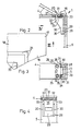
- Fig. 1 of the drawing approximately in natural size - the corner area of an espagnolette fitting 1 for windows, doors or the like is shown. It is composed of two fitting components 2 and 3, which extend essentially at right angles to one another.
- the fitting component 2 has a faceplate 4, while the fitting component 3 has a faceplate 5.
- Both cuff rails 4 and 5 are preferably made of a metallic material, in particular flat steel. They are preferably made from strip material with a flat rectangular cross section.
- the faceplate 4 of the fitting component 2 carries on its rear side an angled profile guide channel 6 with two straight legs 6a and 6b which are oriented approximately at right angles to one another and which are connected in one piece by an arcuately curved middle piece 6c.
- a flexible deflection member 7, for example made of spring steel strip or the like, is arranged exclusively longitudinally and serves for the geared connection of drive rods 8a and 8b, which are each longitudinally displaceably held on the back of the two face plates 4 and 5.
- Driver pins 9a and 9b serve to connect the deflection member 7 to the drive rods 8a and 8b, as can be clearly seen in FIG. 1. While the driver pin 9a of the drive rod 8a is in permanent connection with the deflection member 7 through a longitudinal gap in the profile guide channel 6, the driver pin 9b protrudes through a longitudinal slot 10 in the bottom of the profile guide channel 6 and can be detachably provided with a driver recess 12 in the drive rod 8b be coupled.
- the drive rods 8a and 8b of the drive rod fitting 1 serve to move functional parts, one of which is shown in FIG. 1 of the drawing and is designed as a locking member 13.
- This locking member 13 is arranged along the outer broad side of the faceplate 5 so as to be displaceable in the longitudinal direction thereof and for this purpose is connected to the drive rod 8b via a shaft 14.
- the shaft 14 extends through a longitudinal slot 15 in the faceplate 5, which is only hinted at in FIG. 1.
- the two fitting components 2 and 3 of the connecting rod fitting 1 can be detachably preassembled with one another via their faceplate 4 and 5 by means of a faceplate corner connection 16 to form a functionally reliable unit on the sash or frame of a window or door.
- FIG. 2 of the drawing the frame corner of the wing 17 of a window or a door is indicated, on its horizontal leg 18, the faceplate 4 and on its upright leg 19, the faceplate 5 of the drive rod fitting 1 is to be attached.
- the faceplate 4 and 5 have the purpose of flush-fitting a drive rod groove 20 around the wing corner on their open side, for which they are supported with their two longitudinal edges on steps 21 located on the opening side of this drive rod groove 20.
- Screws 22, which penetrate corresponding holes in the faceplate 4 and 5 and are screwed into the bottom of the drive rod groove 20, are used in a known manner to fasten the faceplate 4 and 5 and thus also the fitting components 2 and 3 to the wing 17.
- the faceplate corner connection 16 is provided.
- the faceplate 4 is provided at its end, for example with the profile guide channel 6, for the purpose of forming a tongue-like projection 23 with notches 24 extending from its longitudinal edges, as can also be clearly seen in FIG. 3.
- holes 25 are provided in the faceplate 4 to form eyelets, for example punched out. Instead of these holes 25, laterally open edge notches on the faceplate 4 can also be used to form the engagement eyelets. It is only important that the holes 25 or the edge notches provided instead form a coupling flank 27 (FIGS. 2 and 3) at a distance behind the transverse edges 26 determined by the notches 24 on the faceplate 4, which are directed essentially transversely to the level of the faceplate 4 .
- a molded part 28 is fastened on the back, which can be produced, for example, as a stamped and bent molded part made of sheet metal.
- the molded part 28 has a web wall 29 which abuts the back of the faceplate 5 and is firmly connected to it, for example welded or riveted.
- Two parallel legs 30 protrude at right angles from the web wall 29, so that the shaped part 28 has an approximately U-shaped cross section in its longitudinal direction. The distance between the outer sides of the two legs 30 is selected so that the molded part 28 can be taken up by the narrower cross-sectional area of the stepped drive rod groove 20 in the wing 17, while the faceplate 5 is able to insert the same in the wider groove steps 21.
- a flap 31 is also bent from the molded part 27, which has a width corresponding to the faceplate 5 and forms a bottom for the molded part 28, which is perpendicular to the adjacent end of the faceplate 5 and also directly adjoins the leg 30 for the lateral limitation of a pocket.
- Each leg 30 of the molded part 28 is provided with a hook 32 which extends essentially parallel to the longitudinal direction of the faceplate 5 and transversely to the plane of the angled tab 31 on the molded part 28.
- the hooks 32 protrude beyond the rear transverse edge 33 of the flap 31, in such a way that an abutment stop 33 is formed on each of the legs 30 of the molded part 28 and extends parallel to the plane of the flap 31.
- the hooks 32 each project beyond the abutment stop 33 adjacent to them in the direction of the angled tab 31, at least to such an extent that their free end at least approximately reaches a plane coinciding with the back of the tab 31, as clearly shown in FIG. 2 can be seen.
- each abutment stop 31 and the inner surface of the angled flap 31 facing it is adapted to the thickness of the faceplate 4, wherein the inner surface of the flap 33 can form a support stop for the tongue 23 of the faceplate 4.
- the faceplate 4 is first pushed with its tongue 23 at an obtuse angle to the faceplate 5 past the hook 32 between the legs 30 and under the tab 33 into the pocket of the fitting 28, as shown in FIG. 2 is indicated by dash-dotted lines. Then the two face plates 4 and 5 are brought into a right-angled position by pivoting transversely to their plane, as can be seen from the solid lines in FIG. 2.
- the hooks 32 penetrate from the rear into the holes 25 or edge notches of the faceplate 4 until the faceplate 4 comes into contact with the rear face against the abutment stops 33.
- a positive coupling of the two faceplate 4 and 5 is then achieved with the aid of the faceplate corner connection 16, which ensures that the faceplate 4 and 5 are securely fixed in position in each other brings about three spatial dimensions before the espagnolette fitting 1 on the legs 18 and 19 of the wing 17 has been inserted into the espagnolette groove 20 and with the faceplate 4 and 5 into the groove steps 17.
- the hooks 32 are provided on their edge facing the faceplate 5 or the tab 31 with an arcuate curved flank 34, as can be seen particularly clearly in FIG. 2.
- the faceplate 4 carries the profile guide channel 6, it is expedient to provide the legs 30 of the shaped piece 28 with a concavely curved edge 35 against which the curved middle piece 6c of the profile guide channel 6 is located for the purpose of additional support on the faceplate rails -Connect 16 creates.
- the tab 31 serving as a support stop for the faceplate 4 with its inner surface is formed directly by an approximately right-angled bend of the faceplate 5.
- the fitting 28 connected to the faceplate 5 has only one leg 30, which is on the longitudinal center plane the faceplate 5 is fixed lying on the back and has a normal position to the faceplate level.
- the shaped piece 28 or the leg 30 forming this has practically the same outline shape as the legs 30 of the shaped piece 28 in the exemplary embodiment according to FIGS. 1 to 4.
- the faceplate 4 in the embodiment according to FIGS. 5 and 6 can be placed on the support stop formed by the inside of the angled flap 31 without hindrance by the shaped piece 28 or the leg 30, it is on its longitudinal center plane with a slot cut 36 open at the end provided, the width of which is matched to the thickness of the leg 30 or of the shaped piece 28. Tongues 37 remain on both sides of this slot incision 36, which come into operative connection with the support stop on the inside of the angled tab 31. At a distance behind the slot incision 36 there is a hole 25 on the longitudinal median plane of the faceplate 4, which forms two flanks 27 which are opposite each other at a distance and are directed transversely to the level of the faceplate 4.
- the hook 32 of the shaped piece 28 or the leg 30 engages when the faceplate 4 is pivoted out of its position indicated by dash-dotted lines in FIG. 6 into the position shown by solid lines , in which case the faceplate 4 on the shaped piece 28 or on the leg 30 is also fixed in position by the abutment stop 33.
- the embodiment of the faceplate corner connection 16 according to FIGS. 7 and 8 differs from that according to FIGS. 5 and 6 essentially in that the faceplate 4 with proper coupling engagement of the faceplate corner connection 16 with the tab bent by the faceplate 5 at right angles 31 comes to lie in the same plane.
- This has the advantage that the drive rods Fitting 1 can also be used in the area of the faceplate corner connection 16 completely flush with the rebate surface of the wing 17 in its drive rod groove 20 or its widened groove steps 21.
- the fitting 28 which is firmly connected to the faceplate 5 or the leg 30 which forms it is arranged such that its boundary edge 38 which faces the inside of the angled flap 31 has a distance from the inner surface of the flap 31 which corresponds at least to the thickness of the faceplate 4 .
- the abutment stop 33 on the shaped piece 28 or leg 30 is provided in such a way that, on the one hand, it lies approximately at the same level as the inner surface of the angled flap 31 forming the support stop, while on the other hand it is arranged in front of the flap 31 at a distance which leaves at least one gap that corresponds to the thickness of the faceplate 4.
- the hook 32 is located on the shaped piece 28 or on the leg 30.
- the faceplate 4 in the embodiment according to FIGS. 7 and 8 has a similar design as the faceplate 4 in the embodiment according to FIGS. 1 to 4. It has a tongue 39 lying on the longitudinal center plane, which is released by notches attached to the faceplate 4 is formed.
- the tongue 39 is cranked out of the plane of the faceplate 4 by an amount towards the rear, which corresponds to the thickness of the angled tab 31 on the faceplate 5th is coordinated.
- the tongue 39 between the support stop on the inner surface of the flap 31 and the edge 38 of the fitting 28 and, respectively, is first shown in the angular position of the faceplate 4 in FIG 30 indented. Then the faceplate 4 is made the position shown in broken lines is pivoted into the position indicated by solid lines. On the one hand, the hook 32 comes into engagement in the hole 25 or between its two flanks 27 on the faceplate 4, while on the other hand the back of the faceplate 4 meets the abutment stop 33.
- a three-dimensionally positive coupling connection between the two cuff rails 4 and 5 is achieved even before the entire connecting rod fitting 1 into the connecting rod groove 20 formed on the wing 17 or its widened groove steps 21 is used.
Landscapes
- Engineering & Computer Science (AREA)
- Mechanical Engineering (AREA)
- Joining Of Corner Units Of Frames Or Wings (AREA)
- Leg Units, Guards, And Driving Tracks Of Cranes (AREA)
Applications Claiming Priority (2)
| Application Number | Priority Date | Filing Date | Title |
|---|---|---|---|
| DE3729214 | 1987-09-02 | ||
| DE19873729214 DE3729214A1 (de) | 1987-09-02 | 1987-09-02 | Stulpschienen-eckverbindung |
Publications (2)
| Publication Number | Publication Date |
|---|---|
| EP0305732A2 true EP0305732A2 (fr) | 1989-03-08 |
| EP0305732A3 EP0305732A3 (fr) | 1990-08-08 |
Family
ID=6334991
Family Applications (1)
| Application Number | Title | Priority Date | Filing Date |
|---|---|---|---|
| EP88112092A Withdrawn EP0305732A3 (fr) | 1987-09-02 | 1988-07-27 | Barre de guidage pour un joint d'angle |
Country Status (6)
| Country | Link |
|---|---|
| US (1) | US4945702A (fr) |
| EP (1) | EP0305732A3 (fr) |
| DE (1) | DE3729214A1 (fr) |
| DK (1) | DK487388A (fr) |
| FI (1) | FI884007A7 (fr) |
| NO (1) | NO883891L (fr) |
Cited By (4)
| Publication number | Priority date | Publication date | Assignee | Title |
|---|---|---|---|---|
| FR2649746A1 (fr) * | 1989-07-13 | 1991-01-18 | Ferco Int Usine Ferrures | Installation pour l'assemblage automatique d'un dispositif de ferrure en particulier d'un verrouillage lateral destine a etre monte sur les ouvrants, notamment de fenetres oscillo-battantes |
| EP0493689A1 (fr) * | 1991-01-03 | 1992-07-08 | Siegenia-Frank Kg | Tringlerie de commande pour fenêtres, portes ou similaires |
| EP0843061A3 (fr) * | 1996-11-18 | 1998-10-21 | ROTO FRANK Aktiengesellschaft | Ferrure pour fenêtre |
| EP1382782A3 (fr) * | 2002-07-18 | 2006-11-15 | Gretsch-Unitas GmbH Baubeschläge | Ferrure |
Families Citing this family (1)
| Publication number | Priority date | Publication date | Assignee | Title |
|---|---|---|---|---|
| DE29911235U1 (de) | 1999-06-28 | 2000-08-17 | Mayer & Co., Salzburg | Eckverbindung für ein Beschlagsystem |
Family Cites Families (10)
| Publication number | Priority date | Publication date | Assignee | Title |
|---|---|---|---|---|
| US3603628A (en) * | 1969-07-07 | 1971-09-07 | Edward A Smith | Frame connector structure |
| DE2327086A1 (de) * | 1973-05-28 | 1974-12-19 | Siegenia Frank Kg | Stulpschienen-eckverbindung, insbesondere an treibstangenbeschlaegen |
| DE2327836B2 (de) * | 1973-06-01 | 1980-07-31 | Siegenia-Frank Kg, 5900 Siegen | Stulpschienen-Kupplung an einer Ecke von Treibstangenbeschlägen für Fenster, Türen o.dgl |
| DE7721136U1 (de) * | 1977-07-06 | 1977-10-13 | Wilh. Frank Gmbh, 7022 Leinfelden- Echterdingen | Eckverbindung |
| FR2398168A1 (fr) * | 1977-07-22 | 1979-02-16 | Tubauto | Dispositif d'assemblage de cadres rigides destines au montage de portes, fenetres et analogues |
| US4197952A (en) * | 1978-05-18 | 1980-04-15 | Lear Siegler, Inc. | Storage unit and post and beam of the unit |
| US4308692A (en) * | 1979-06-21 | 1982-01-05 | Rumble Roy W | Door frame kit |
| US4352433A (en) * | 1979-12-14 | 1982-10-05 | Kirsch Company | Rod and bracket assembly |
| DE3245671A1 (de) * | 1982-12-09 | 1984-06-14 | Fa. Aug. Winkhaus, 4404 Telgte | Stulpschienen-treibstangeneinheit |
| US4513554A (en) * | 1982-12-27 | 1985-04-30 | Lawrence Brothers, Inc. | Barn door framing system |
-
1987
- 1987-09-02 DE DE19873729214 patent/DE3729214A1/de not_active Ceased
-
1988
- 1988-07-27 EP EP88112092A patent/EP0305732A3/fr not_active Withdrawn
- 1988-08-31 FI FI884007A patent/FI884007A7/fi not_active Application Discontinuation
- 1988-08-31 US US07/239,108 patent/US4945702A/en not_active Expired - Fee Related
- 1988-09-01 NO NO88883891A patent/NO883891L/no unknown
- 1988-09-02 DK DK487388A patent/DK487388A/da not_active Application Discontinuation
Cited By (6)
| Publication number | Priority date | Publication date | Assignee | Title |
|---|---|---|---|---|
| FR2649746A1 (fr) * | 1989-07-13 | 1991-01-18 | Ferco Int Usine Ferrures | Installation pour l'assemblage automatique d'un dispositif de ferrure en particulier d'un verrouillage lateral destine a etre monte sur les ouvrants, notamment de fenetres oscillo-battantes |
| EP0414582A1 (fr) * | 1989-07-13 | 1991-02-27 | FERCO INTERNATIONAL Usine de Ferrures de BÀ¢timent Société à responsabilité limitée | Installation pour l'assemblage automatique d'un dispositif de ferrure en particulier d'un verrouillage latéral destiné à être monté sur les ouvrants, notamment de fenêtre oscillobattantes |
| US5095614A (en) * | 1989-07-13 | 1992-03-17 | Ferco International Usine De Ferrures De Batiment | Automatic window frame lock assembly installation |
| EP0493689A1 (fr) * | 1991-01-03 | 1992-07-08 | Siegenia-Frank Kg | Tringlerie de commande pour fenêtres, portes ou similaires |
| EP0843061A3 (fr) * | 1996-11-18 | 1998-10-21 | ROTO FRANK Aktiengesellschaft | Ferrure pour fenêtre |
| EP1382782A3 (fr) * | 2002-07-18 | 2006-11-15 | Gretsch-Unitas GmbH Baubeschläge | Ferrure |
Also Published As
| Publication number | Publication date |
|---|---|
| NO883891D0 (no) | 1988-09-01 |
| DK487388D0 (da) | 1988-09-02 |
| NO883891L (no) | 1989-03-03 |
| US4945702A (en) | 1990-08-07 |
| DE3729214A1 (de) | 1989-03-16 |
| FI884007A7 (fi) | 1989-03-03 |
| EP0305732A3 (fr) | 1990-08-08 |
| DK487388A (da) | 1989-03-03 |
| FI884007A0 (fi) | 1988-08-31 |
Similar Documents
| Publication | Publication Date | Title |
|---|---|---|
| EP2118414B1 (fr) | Armature de verrouillage et ensemble de pièces pour cette armature | |
| EP0305731B1 (fr) | Barre de guidage pour un joint d'angle | |
| DE2741408C2 (de) | Treibschienenbeschlag | |
| DE8323365U1 (de) | Treibstangenbeschlag fuer fenster, tueren od. dgl. | |
| DE8304739U1 (de) | Eckumlenkung eines in hinterschnittene profilnuten oder rahmenprofile von fenster und tueren aus metall, kunststoff od. dgl. einsetzbaren treibstangenverschlusses | |
| EP0493689B1 (fr) | Tringlerie de commande pour fenêtres, portes ou similaires | |
| DE202009005885U1 (de) | Treibstangenschloss mit Falle und Schubriegel | |
| DE7603047U1 (de) | Ueberlappungsverbindung zwischen stulpschienen von treibstangenbeschlaegen | |
| EP0305732A2 (fr) | Barre de guidage pour un joint d'angle | |
| DE2033042A1 (de) | Getriebe für Treibstangenbeschläge | |
| DE3150029C2 (de) | Treibstangenverschluß mit Eckumlenkung für Fenster und Türen od.dgl. | |
| DE3127929A1 (de) | Eckumlenkung fuer treibstangenbeschlaege von fenstern und tueren od. dgl. | |
| DE8127451U1 (de) | Eckumlenkung fuer treibstangenbeschlaege | |
| AT403500B (de) | Beschlagteileverbindung | |
| DE2461228C3 (de) | Verfahren zum Herstellen eines an eine jeweils vorgegebene Flügelhöhe angepaßten, einbaufertigen Fenster- oder Türverschlusses | |
| DE2318408A1 (de) | Schliesstueck mit steg, insbesondere fuer mittelverschluesse an schwenk-kippfenstern | |
| CH626682A5 (en) | Edge mechanism for a window or door | |
| DE2450760A1 (de) | Beschlag fuer ein fenster, eine tuer od. dgl. | |
| DE2366635C2 (de) | Stulpschienen-Eckverbindung | |
| EP0695849B1 (fr) | Dispositif d'assemblage d'angle pour éléments d'encadarement de fenêtres, portes ou similaires | |
| DE3439545C2 (fr) | ||
| DE7309253U (de) | Vorrichtung zum laengeneinstellbaren verbinden von schubstangen und/oder schubgliedern eines beschlages fuer ein fenster eine tuer od.dgl. | |
| DE3203319A1 (de) | Treibstangenbeschlag | |
| DE2925671A1 (de) | Eckverbindung eines treibstangenbeschlages fuer fenster, tueren o.dgl. | |
| DE7721136U1 (de) | Eckverbindung |
Legal Events
| Date | Code | Title | Description |
|---|---|---|---|
| PUAI | Public reference made under article 153(3) epc to a published international application that has entered the european phase |
Free format text: ORIGINAL CODE: 0009012 |
|
| AK | Designated contracting states |
Kind code of ref document: A2 Designated state(s): AT BE CH DE ES FR GB IT LI NL SE |
|
| PUAL | Search report despatched |
Free format text: ORIGINAL CODE: 0009013 |
|
| AK | Designated contracting states |
Kind code of ref document: A3 Designated state(s): AT BE CH DE ES FR GB IT LI NL SE |
|
| STAA | Information on the status of an ep patent application or granted ep patent |
Free format text: STATUS: THE APPLICATION IS DEEMED TO BE WITHDRAWN |
|
| 18D | Application deemed to be withdrawn |
Effective date: 19910201 |