EP0306305A2 - Bildbehandlungsprozessor mit zeitverschachteltem Bus mit freiem Fluss - Google Patents
Bildbehandlungsprozessor mit zeitverschachteltem Bus mit freiem Fluss Download PDFInfo
- Publication number
- EP0306305A2 EP0306305A2 EP88308095A EP88308095A EP0306305A2 EP 0306305 A2 EP0306305 A2 EP 0306305A2 EP 88308095 A EP88308095 A EP 88308095A EP 88308095 A EP88308095 A EP 88308095A EP 0306305 A2 EP0306305 A2 EP 0306305A2
- Authority
- EP
- European Patent Office
- Prior art keywords
- bus
- data
- address
- digital image
- pipeline
- Prior art date
- Legal status (The legal status is an assumption and is not a legal conclusion. Google has not performed a legal analysis and makes no representation as to the accuracy of the status listed.)
- Granted
Links
Images


Classifications
-
- G—PHYSICS
- G06—COMPUTING OR CALCULATING; COUNTING
- G06T—IMAGE DATA PROCESSING OR GENERATION, IN GENERAL
- G06T1/00—General purpose image data processing
- G06T1/20—Processor architectures; Processor configuration, e.g. pipelining
Definitions
- the present invention relates to digital image processing systems.
- the present invention relates to a digital image processing system which permits free flow of high speed image data and addresses in a pipelined architecture.
- the present invention is an image processing system in which the various components of the image processing system communicate with one another by transferring addresses and data in parallel over a pipeline bus.
- the image processing system includes image memory means for storing digital image data, intensity processor means for performing processing functions on the image data, and address generator means for generating addresses. All of these components communicate with one another over the pipeline bus.
- the pipeline bus uses a handshaking protocol which permits very high speed address and data transfer but has a start/stop free flow format which permits the pipeline bus to run at any throughput rate. This is important in pipelined image processing because the computational complexity varies from operation to operation.
- the pipeline bus permits free flow through all components connected to the pipeline bus regardless of the operation being performed, without sacrificing indefinitely sustainable high transfer rates.
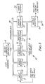
- FIG. 1 shows digital image processor 10, which is a video rate, free flow pipelined image processor which uses the pipeline bus architecture of the present invention.
- digital image processor 10 includes microcomputer controller 12, input interface 14, image memory 16, address generator 18, intensity processor 20, display formatter 22, video display 24, and output interface 26. Communication among the components of image processor 10 is provided primarily over two separate buses' standard bus 28 and pipeline bus 30.
- Standard bus 28 is preferably an industry standard type of computer bus (such as VME or Multi-bus) and is used for communication of control information between microcomputer controller 14 and the other components of digital image processor 10.
- pipeline bus 30 includes pipeline address bus (PA) 34, pipeline data (PD) bus 36, and master timing (MT) bus 38, which are shown in Figures 2A-2C, respectively. All transfers of image data among the components of digital image processor 10 are conducted over pipeline bus 30.
- PA pipeline address bus
- PD pipeline data
- MT master timing
- Microcomputer controller 12 provides an interface between digital image processor 10 and the user. Depending on the particular user commands provided to microcomputer controller 12, it sends signals over standard bus 28 to the individual components to configure them to perform the desired image processing task.
- Input interface 14 receives high speed line-by-line input image data, or other input image data, representing a digital image.
- the input data can be, for example, from a computer or from data storage devices.
- Image memory 16 is a read/write memory which stores digital image data. Input data from input interface 14 is written into image memory 16 (as is processed image data from intensity processor 20). Image data is read from image memory 16 to provide input to intensity processor 20 and to provide output to display formatter 22 and output interface 26.
- Address generator 18 generates the stream of addresses over pipeline bus 30 which address image memory 16 to cause digital image data to be transferred; for example, from image memory 16 to intensity processor 20 for processing. ln addition, address generator 18 communicates directly with intensity processor 20 over functional address lines 32 to control the functional image processing operations being performed by intensity processor 20.
- Display formatter 22 converts digital image data to display drive signals which drive video display 24.
- video display 24 is a raster scan video monitor
- display formatter 22 converts the digital image data representing individual pixels of the display into analog video signals used by video display 24.
- Display formatter 22 preferably permits asynchronous operation of video display 24 with respect to the remainder of digital image processor 10. By eliminating the need to synchronize operation to the video sync rate of video display 24, a free flow stop/start transfer of data over pipeline bus 30 is possible.
- Output interface 26 allows digital image processor 10 to communicate with other digital equipment by a high speed line-by-line transfer of data.
- the format of the data being transmitted by output interface 26 is, in one embodiment, similar to the format of data being received by input interface 14.
- Intensity processor 20 performs pipelined image pixel intensity computations based on input data received from image memory 16 and functional addresses received from address generator 18.
- intensity processor 20 uses adaptive finite impulse response (FIR) filtering to perform a wide variety of different intensity computations.
- FIR finite impulse response
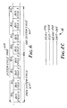
- image data is transferred by sub-image blocks.
- Each block is an N X N square of spatially contiguous pixels.
- the sub-image block is a 4x4 block -- i.e. each block represents sixteen pixels.
- this address 310 represents the upper lefthand pixel of each 4x4 pixel block, 308 as illustrated schematically in Figure 3.
- this address 310 represents the upper lefthand pixel of each 4x4 pixel block, 308 as illustrated schematically in Figure 3.
- each pixel is represented by eight bits.
- the 4x4 pixel square is transmitted over pipeline bus 30 as four 32-bit sequential words.
- "Word 0" represents the top row 312 of the 4x4 block and is a 32-bit word formed by the four 8-bit pixels of the top row.
- "word 1", "word 2", and “word 3” are 32-bit words formed by a row of four 8 bit pixels.
- "Word 3" represents the bottom row of the block.
- Pipeline bus 30 has three major parts, pipeline address (PA) bus 34, pipeline data (PD) bus 36, and the master timing (MT) bus 38. Depending on the number of components to be connected to pipeline bus 30, and the particular processing requirements, more than one PA bus 34 and more than one pipeline data (PD) bus 34 is provided. In the preferred embodiment which will be described, pipeline bus 30 includes two PA buses 34A and 34B, and six PD buses 36A-36F. PA bus 34 of Figure 2A and PD bus 36 of Figure 2B are typical of each PA and PD bus in pipeline bus 30.
- PA bus 34 carries physical addresses in image memory 16 of bit-mapped data, as well as control and routing information for that data. PA bus 34 initiates operations that will occur over one or more of the PD buses 36. PA bus 34 is a tri-stated bus which is terminated to the high logic state at its physical start and end points.
- a bus cycle on PA bus 34 is the equivalent of two system clocks, as illustrated in Figure 4.
- a bus cycle is the duration that a single address is resident on PA bus 34.
- a system cycle 422, as shown in Figure 4 is a time period that is four bus cycles (410-413) in duration.
- the system cycle (422) defines the periodicy of PA bus 34.
- Each bus cycle (410-413) of the system cycle (422) is designated as Bus Cycle 0 (410), Bus Cycle 1 (411), Bus Cycle 2 (412), or Bus Cycle 3 (413).
- PA bus 34 The components which use the PA bus 34 are either PA masters or PA slaves.
- a PA master is the source of data on PA bus 34.
- a PA slave is the recipient of data on PA bus 34. All PA slave responses occur two system cycles (422) after the system cycle (422) in which the pA master initiated the operation.
- PA bus 34 is a fixed four-to-one time division multiplexed bus with fixed masters activated each bus cycle (410 - 413) of every system cycle (422).
- each PA master has a designated time slot (one of the bus cycles(410 -413)) in each system cycle (422).
- PA bus 34 has a total of 35 lines, including 26 address lines and 9 control lines.
- "X" physical address lines XPO-XP12 (210) and “Y” physical address lines YPO-YP12 (212) are asserted by the PA master.
- the input/output line I/0 (222) is set by the PA master to "0".
- lines XPO-XP12 (210) define an X physical address in image memory 16 (corresponding to the X coordinate of the upper lefthand pixel of the desired 4x4 subimage block).
- lines YPO-YP12 (212) define a Y physical address in image memory 16 corresponding to the Y coordinate of the upper left hand pixel of the 4x4 subimage block.
- the not parallel address ready (NPAR) line (214) is a control or handshake line which is asserted by the master and is used to indicate that a valid parallel address is present on PA bus 34. When the NPAR line (214) is "0", a valid parallel address is present. When the NPAR line (214) is "1", this indicates that pA bus 34 is inactive.
- FIG. 5 shows schematically a PA master's request and a PA slave's response (512) two system cycles later.
- NPAD line (216) When the NPAD line (216) is "0", it indicates that the address has been detected by a PA slave. When the NPAD line (216) is "1", it indicates that an address has not been detected.
- the NPAS line (218) permits multiple PA slaves to synchronize to a single PA master.
- the NPAS line (218) is "0" it represents a PA slave request to the PA master to hold the address which had been asserted on the XPO-XP12 (210) and YPO-YP12 (212) lines.
- the PA master is required to repeat that address during its turn in the next system cycle.
- the NPAS line (218) is "1" it indicates that all PA slaves are ready.
- the read/write (R/W) line (220) is asserted by the master.
- a "1" on the R/W line (220) designates a read operation, and a "0" designates a write operation.
- the input/output line (I/0) (222) indicates whether the operation is involving image memory 16 or is a parameter passing operation.
- a “0" on the I/0 line (222) designates the operation as involving image memory 16, while a "1" designates a parameter passing operation.
- the operation mode (MODE) line (224) is also asserted by the PA master.
- a "0" on the MODE line (224) designates a non-interlaced transfer, and a "1" indicates an interlace transfer.
- the I/0 (222) and MODE (224) lines are used to select the format for data transferred over PD bus 36. The operation of these formats will be described in more detail in the context of PD bus 36.
- image memory 16 is capable of storing multiple planes of pixel data.
- the same two-dimensional X and Y address coordinates apply to each plane. Multiple planes are used, for example, where three- or four-color image data has been scanned and stored. In that case, each plane represents one color.
- the plane number lines PO (226) and Pl (228) define a two bit number.
- the plane group (PG) line (230) selects either single plane operation (when it is "0") or multiple-plane operation (when it is "1"). For multiple-plane operation, the PG line (230) is "1", indicating that all planes from "0" through the plane number are to be addressed with the same X and Y address coordinates.
- the plane number defined by PO (226) and Pl (228) is simply the plane to be used for the particular operation. If the PG line (230) is "1", the plane number designates the final plane of the plane group to be used in that operation.
- the plane number lines PO (226) and Pl (228) and the PG line (230) are asserted by the PA master.
- Pipeline data (PD) bus 36 shown in Figure 2B contains bit mapped image or graphics data for transmission between components of image processor 10 and preferably is connected to internal parameter registers of each component for the passing of control parameters.
- PD bus 36 is a tri-stated bus which is terminated at the high state at its physical start and end points.
- the components which use PD bus 36 can be classifed as PD masters and PD slaves.
- a PD master is a device that controls transfers on PD bus 36. All PD masters are unconditionally in control of the PD bus during their time slot. Each PD master must know a priori the PD slaves which are unconditionally on PD bus 36.
- a PD slave is a device that responds to a PD master's request.
- a PD slave is conditionally on PD bus 36 during a time slot and is activated by a valid address appearing on PA bus 34.
- Each PD slave must know internally which PD bus to use for every access code on PA bus 34.
- the bus cycle (410 - 413) is the equivalent of two system clocks (420), and there are four bus cycles (410 - 413) in a system cycle (422). All operations on PD bus 36 take a full system cycle (422) to occur.
- All system cycles (422) occur on a pair-wise basis on the PD bus 36. These cycle pairs (610) are broken into odd (612) and even (614) cycles, as illustrated in Figure 6.
- a PD master may be in one of four states at any instant. If both the even (614) and odd (612) cycles are unconditionally off, the PD master is off the PD bus 36. If the even cycle (614) is unconditionally on and the odd cycle (612) is unconditionally off, the PD master uses only the even cycle (614) for data transfer. Conversely, if the even cycle (614) is unconditionally off and odd cycle (612) unconditionally on, the master uses only the odd cycle (612) for data transfer. Finally, if both the even (614) and odd (612) cycles are unconditionally on, the master uses both cycles (612 & 614) for data transfer.
- PD bus 36 contains 40 lines -- thirty-two lines for thirty-two bits of parallel data.
- PDOO-PD07 define parallel data byte 0.
- PD10-OD17 define parallel data byte 1.
- PD20-PD27 (236) define parallel data byte 2.
- PD30-PD37 (238) define parallel data byte 3.
- the source of the data for data bytes 0-3 is determined by the state of the read/write (R/W) line (220) of PA bus 34. If the R/W line (220) is "0", the source of the data bytes is the PD master (since this is a write operation). Conversely, if the R/W line (220) is "1" (indicating a read operation), the source of the data bytes on PD bus 36 is the PD slave.
- either the PD master or the PD slave can determine whether or not particular data bytes are to be used, modifiable on a 4x4 block-by-block basis. If one of the not write byte lines (246, 248, 250, 252) (for example NWB1 (248)) is a "0", this means that data byte "1" is valid data. Conversely, if NWB1 (248) line is 1, the source of the data has indicated that data byte 1 is not to be used during this operation.
- the transfer of data over PD bus 36 is in different formats, depending on the state of the I/0 and MODE (224) lines of PA bus 34. If the I/0 line (222) is "1", the thirty-two bits of data appearing on lines PDO-PD7 (232), PD1O-PD17 (234), PD20-PD27 (236), and PD30-PD37 (238) remain constant over the entire system cycle (432). This is a parameter passing operation, and the address appearing on PA bus 34 is derived from standard bus 28.
- the MODE line (224) of PA bus 34 selects whether the thirty-two bits data transferred when the I/0 line (222) is "0" are in the form of a 4x4 pixel contiguous region or is in the form of a 2x8 pixel interlaced region.
- Figure 7A shows the 4x4 subimage block (710) which is passed when the MODE line (224) is "0". This is the standard subimage block (710) used for transferring data over pipeline bus 30.
- Figure 7B shows the 2x8 interlaced region (712) which is transferred when the MODE line (224) is "1".
- the remote data enable (RDE) line (254) of PD bus 36 is used for communication with a remote slave through input interface 14.
- RDE remote data enable
- the PD master asserts data over PD bus 36.
- the PD master receives data from the remote slave over PD bus 36.
- PD bus 36 includes three handshake lines: the not parallel data ready (NPDR) line (240); the not parallel data accepted (NPDA) line (242); and the not parallel data sync (NPDS) line (244).
- NPDR not parallel data ready
- NPDA not parallel data accepted
- NPDS not parallel data sync
- the NPDR line (240) is asserted by the PD master and indicates whether or not the PD master is ready to either accept data or to transmit data. A “1" on the NPDR line (240) indicates that the PD master is not ready, while a “0" indicates that the PD master is ready.
- the PD slave If the PD slave has accepted the data or has placed valid data on the data lines of PD bus 36, it will cause the NPDA line (242) to drop from "1" to "0". A "1" on the NPDA line (242) means that the PD slave has not accepted data or has not placed data on the data lines. Because the NPDA signal (242) is a pulse, in the pipelined architecture of the present invention there is time to either place new data on the PD bus 36 at the next Bus cycle (410 - 413) or to repeat the same data again. As shown in Figure 8, the PD master always asserts the NPDR line (240), and the PD slave always asserts the NPDA line (242) at the appropriate bus cycle time (e.g. Bus cycle 2 (412)) to allow the PD master to react to the status.
- Bus cycle 2 412
- any component on PD bus 36 determines that it wants to abort the data transfer for any reason, it drops the NPDS line (244) during Bus cycle 2 (412). Either a PD master or a PD slave can assert the NPDS signal (244). As long as the NPDS (244) line is "1" all components are ready for data. If the NPDS line (244) is "0", this constitutes a request by the asserting device that the PD master hold the data for this system cycle and (422) repeat it the next valid system cycle (422).
- any PD slave feels that it is not prepared for a particular transfer, it can drive the NPDS line low (244) ("0") and essentially abort the whole system cycle (422) for all components. Once all of the components agree that they are ready for the transfer of data, the NPDS line (244) will remain "1" for the entire system cycle (422) and the system cycle (422) will proceed normally. This forces a synchronization on PD bus 36 so that all transfers are always completely valid transfers of data regardless of the number of PD slaves on the PD bus.
- master timing (MT) bus 38 includes system clock lines SCLK+ (256) and SCKL- (258), a master sync (MSYNC) line (260), and a system initialize (SINIT) line (262).
- SCLK+ (256) and SCKL- (258) are positive and negative polarities of a differential ECL system clock signal which, in a preferred embodiment, operates at 20 mHz.
- the SINIT signal shown in Figure 9B is an initialization signal for the entire system. Normally, the SINIT signal (262) is "1". When an initialization is to take place, SINIT (262) is "0" for two system clocks (420).
- address calculation and generation and data calculation are performed separately in address generator 18 and intensity processor 20, respectively.
- image processor 10 of the present invention preferably pipelines both address calculations as well as data calculations. As a result, the generation of addresses is not a limiting factor in high speed operation.
- PA bus 34 has a free flow characteristic, meaning that an address placed on PA bus 34 is assigned to a time slot in the pipeline. If that address cannot be immediately accepted by image memory 16, handshaking takes place which allows the same address to again be placed on PA bus 34 at the next occurrence of its time slot. This may be repeated as many times as required for the address to be accepted.
- This free flow characteristic therefore, effectively results in starting and stopping of PA bus 34.
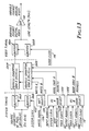
- Figure 10 shows a preferred embodiment of address generator 18, which is a pipelined address generator having a stop/start capability so that it is compatible with the free flow characteristic of pipeline bus 30.
- address generator 18 includes address pipeline 40, first-in, first-out (FIFO) buffer 42, functional address generator 44, and control 46.
- Address pipeline 40 generates addresses at a high rate of speed through a pipelined architecture, and may be stopped on demand by control 46. Addresses are calculated parametrically by address pipeline 40 and are supplied to FIFO buffer 42, which interfaces with the address lines of PA bus 34.
- FlFO buffer 42 is a first-in, first-out memory that absorbs the speed variations between the starting/stopping of PA bus 34 and the starting/stopping of address pipeline 4D.
- Control 46 interfaces with the handshake lines of PA bus 34 and provides control signals to address pipeline 40, FIFO buffer 42, and functional address lookup table 44. When the PA bus 34 stops and FIFO buffer 42 begins to fill, control 46 halts address pipeline 40.
- Address pipeline 40 includes parameter generator 48, S T U registers 50, world image space calculator 52, X Y Z registers 54, subimage sequencer 56, address limiter and address builder 58, and memory management unit (MMU) 60.
- parameter generator 48 S T U registers 50
- world image space calculator 52 world image space calculator 52
- X Y Z registers 54 subimage sequencer 56
- address limiter and address builder 58 address limiter and address builder 58
- MMU memory management unit
- the head of the address pipeline is parameter generator 48. This is where addressing coordinates S, T and U are calculated by an additive process.
- address generator 18 shown in Figure 10 parametric calculation of addresses is performed directly, rather than by an accumulative technique used in prior art image processors. By direct calculation, each address is calculated separately, without reliance on previous addresses. As a result, no accumulated errors are produced.
- Parameter generator 48 passes the S, T and U parameters which it has calculated to S T U registers 50.
- World image space calculator 52 draws the S T U coordinates from registers 50 and converts them to X Y Z coordinates (as needed) by use of parametric equations calculated by a multiply and add process.
- the output of world image space calculator 52 is stored in x Y Z registers 54.
- the output of X Y Z registers 54 is supplied to subimage sequencer 56, where an M x M block of addresses are constructed around the (X Y Z) base address by a counting process.
- the X Y Z coordinates are not memory locations, but rather are logical addresses.
- Subimage sequencer 56 allows the address pipeline 40 to create a subimage which, rather than being a 4x4 block, may be 8x8, 12x12 or 16x16 pixels depending on the particular operation to be performed.
- Address limiter and address builder 58 separate the X Y Z address into required and nonrequired bits.
- the required bits are arranged to build a two-dimensional or three-dimensional virtual address.
- the nonrequired bits are combined to form an overflow detection feature.
- MMU 60 is preferably a lookup table where the virtual or logical address from address limiter and address builder 58 is mapped into a physical address space within image memory 16.
- the output of MMU 60 is a physical address which is supplied to FIFO buffer 42 and ultimately on to PA bus 34.
- Functional address lookup table 44 also uses the X Y Z coordinates from registers 54 to produce a functional address on functional address bus 32.
- This functional address is supplied to intensity processor 20 and are used to select filter coefficients used by intensity processor 20 (as will be described in further detail later).
- the rate at which functional address bus 32 is supplying functional addresses can vary from the rate of PA bus 34. In preferred embodiments, however, intensity processor 20 has a FIFO buffer for receiving functional addresses, so that the functional addresses supplied by address generator 18 over functional address bus 32 correspond to data being supplied to intensity processor 20 over pipeline bus 30.
- Address generator 18 shown in Figure 10 with its parametric pipeline address generation, is capable of performing very complex address generation functions without speed degradation. It also allows PA bus 34 to operate at whatever speed is required, without any loss of pixel data or address data or any reduction in the functionality of the address calculation functions. This interfacing is achieved through FIFO buffer 42 and control 46 together with the handshake lines of PA bus 34.
- command load registers (not shown) define coefficients, upper and lower bounds of parameters, and parameter increment values used by address pipeline 40 in the calculation of coordinates, and ultimately of the addresses which are supplied over PA bus 34.
- FIG 11 is a functional block diagram of image memory 16, which functions as a pipelined image memory tile.
- image memory 16 includes pipeline address input registers 62A and 62B, address cache 64, DRAM memory 66, holding register 68, and data ports 70A-70F.
- image memory 16 interfaces through input registers 62A and 62B with two PA buses 34A and 34B, respectively.
- output data ports 70A-70F image memory 16 interfaces with six PD buses 36A-36F, respectively.
- Address cache 64 is a first-in, first-out type of memory. When address cache 64 fills so that there are too many addresses, it refuses further addresses over PA buses 34A and 34B. All addresses are examined an either ignored, accepted (entered into address cache 64), or rejected with a repeat request using the NPAS line of PA bus 34A or 34B to indicate a not ready condition.
- addresses from address cache 64 are read into DRAM 66 where they are adjusted for spatial continuity.
- a sixteen-pixel word in a 4x4 square configuration of spatially contiguous pixels is loaded into holding register 68. Once in holding register 68, the 4x4 pixel bIock is placed out on one of the six PD buse 36A-36F using the format described in Figure 7A.
- data representing a 4x4 pixel block is taken from one of the data ports 70A-70F and loaded into holding register 68.
- An address from address cache 64 is then loaded into DRAM array 66 and adjusted for its spatial continuity to select the 4x4 pixel block into which the data is to be written.
- the free flow characteristics of pipeline bus 30 is reflected in the operation of image memory 16. If the PD bus 36A-36F has slowed down due to handshaking, data will not be entering or exiting holding register 68 at as high a rate. This slows down the use of addresses from address cache 64. Since address cache 64 is not using addresses as rapidly, it will fill and begin rejecting further addresses on PA buses 34A and 34B so that PA buses 34A and 34B begin to slow down. In other words, handshaking on the PD buses 36A-36F will cause a slow down of memory fetches in the memory tile which causes a changing effect on PA buses 34A and 34B so that there is an interrelationship between the free flowing characteristics of the PD and PA buses.
- An important feature of the image memory 16 is the ability to transmit spatially contiguous data in the 4x4 pixel format for any address received over the PA bus (defined by XPAO-XPA12 (210) and YPAO-YPA12 (212)).
- Conventional buses permit only addresses that are integer multiples of the block size (or word size) of the bus. For example a thirty-two bit, four-pixel READ or WRITE on a conventional bus would permit only integer multiples of four to be received over the address bus. This can lead to severe performance degradation in some image processing functions because multiple READS would be required to form a region of computational dependency. In large data base systems, such as those typical of high resolution image processing, this must also be valid even when the image spans multiple memory cards. Since there is a spatial boundary between memory cards, multiple memory cards may be required to contribute a single 4x4 block transfer as shown.
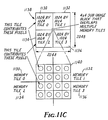
- a memory tile has its memory chips organized into the sixteen memory groups (,) through (3,3) shown in Figure 11.
- a memory tile has a size defined by the number of memory chips and the size of the memory chip (i.e., 32 256K DRAMS creates a 1024x1024 memory tile 1110).
- Each group (M,N) holds all of the pixels in the memory tile that are defined by Eq. 1 above, provided that X and Y are not greater than the size of the tile.
- These separate pixels are held within different locations (L) (1112) within the memory group as shown in Figure 11A.
- Spatially contiguous 4x4 subimage blocks are read/written from the memory tile by controlling the locations: within each group.
- a single 4x4 subimage block (1120) may draw from as many as four different locations (1122, 1124, 1126, 1128) within the groups as shown in Figure 11B.
- each memory tile must contribute certain pixels to the 4x4 block (1140) as if the request was from the center of a tile This process is the concatenation of memory tiles.
- Each memory tile (TILE 0) (1130) decodes the PA address of itself and the three neighbors (TILES 1-3) (1132 - 1136) adjacent to it. It declares one of five states to exist: (1) not one of TILE 0, (1130), TILE 1 (1132), TILE 2 (1134), TILE 3 (1136), (2) TILE 0 (1130) addressed; (3) TILE 1 addressed (1132), (4) TILE 2 (1134) addressed, (5) TILE 3 (1136) addressed. If condition (1) is declared this memory tile does not participate in the operation. If one of conditions (2)-(5) exists the memory tile must decide if it will be required to contribute to the corresponding PD bus transfer. This is accomplished by examining the lower address to see if it falls within a three-pixel border along the memory tile seams (boundaries).
- the address falls outside the three-pixel border, then no concatenation will occur. If it falls within the three-pixel border concatenation must occur. If concatenation must occur, the two least significant bits (LSB) of X, and the two least significant bits (LSB) of Y and the quadrant are stored internally in the memory tile and used to control the data when transmitted over the PD bus.
- the PD bus is controlled as follows:
- image memory 16 decodes the quadrant, the X LSBS, the Y LSBS and the bus cycle (0, 1, 2, 3) on the PD bus to identify which bus cycles and bytes the memory tile must be ON (contributing to the transfer) or OFF (letting another memory tile contribute to this transfer).
- This circuit causes the PD bus memory concatenation in such a way the receiving master device perceives no difference on the PD bus.
- the NPDS line is dropped if image memory 16 is not ready to contribute its data.
- FIG 12 is a functional block diagram of intensity processor 20.
- intensity processor 20 is a circuit that performs pipelined image pixel intensity computations using adaptive finite impulse response (FIR) filtering. By changing filter coefficents, a wide variety of different intensity computation operations can be performed.
- FIR finite impulse response
- intensity processor 20 has four input ports (functional address input port 72, I2 port 74, I1 port 76, and TAG port 78) and one output port 80.
- Image processor 20 includes I2 buffer 82, I1 buffer 84, TAG buffer 86, control RAM 88, I2 functional memory and coefficient store 90, I1 functional memory 92, subimage scanner 94, adaptive FlR 96, accumulator 98, output functional memory 100, and output buffer 102.
- the I1 (1210), I2 (1212) and TAG (1214) inputs are bit-mapped images received from image memory 16. All three inputs can be generated simultaneously with the same address from address generator 18 to image memory 16, or may be generated separately and transmitted over three of the four address channels on the PA bus without sacrificing throughput. In other words, I1 (1210), I2 (1212) and TAG (1214) represent different planes which can be addressed.
- the input images I1 (1210), I2 (1212) and TAG (1214) are received over three separate PD buses 36A-36C in subimage blocks with a 4x4 pixel square geometry. These subimage blocks are concatenated together to form larger subimages and then are fed into an arithmetic pipeline.
- the functional address input is received over functional address bus 32 from address generator 18 and shares I2 buffer 82 with I2 port 74.
- the functional addresses select filter coefficients to be used by adaptive FIR filter 96. Filter coefficients that change with time are loaded into I2 functional memory and coefficient store 90 (which is implemented in a preferred embodiment as a look-up table) and are selected by the functional address (which is different depending on the address in the image).
- the TAG image (1214) is fed into control RAM 88 that selects coefficients (tap weights) to be applied to the I1 (1210) and I2 (1212) images.
- the TAG input (1214) allows the intensity processing operation to vary on a pixel-by-pixel basis.
- the selection of coefficients by the functional addresses can also be affected by the TAG inputs (1214) through control codes supplied by control RAM 88 to store 90.
- I1 function memory 92 and I2 function memory and coefficient store 90 are preferably look-up tables which perform preprocessing of the I1 (1210) and I2 (1212) images received from buffers 84 and 82, respectively.
- the particular function memory page of the look-up table used for preprocessing is based on control codes from control RAM 88, which are selected by the TAG inputs (1214).
- a typical form of preprocessing performed in FM 90 and FM 92 is gray scale transformation.
- the subimage scanner 94 reads pixels in the region of computational dependency and inserts them into the pipeline through control RAM 88 in a sequential fashion. This allows variation of filter size weights based on computational dependency of surrounding pixels.
- FIR 96 includes a combiner for performing what may be termed "post filtering" combiner functions such as add, subtract, multiply, divide, OR, XOR and AND. These combiner functions are selected by combiner codes from control RAM 88 based on the TAG inputs. The final results are passed to output functional memory 100 and are stored in output buffer 102.
- Output buffer 102 acts as a first-in/first-out memory and permits pipelined intensity computations to occur.
- Upper buffer 102 is connected, through upper port 80, to pipeline data buses 36A-36F.
- intensity processor 20 is capable of performing a wide variety of different intensity processing computations which are selectable by address generator 18 under the control of microcomputer controller 12 and by the TAG inputs (1214). All that is required to change from one type of image processing to another is simply to change the coefficients or tap weights to the adaptive FIR filter, function memory pages, and/or combiner codes. These tap weights, function memory and combiner codes can be changed through the functional addresses produced by address generator 18, and also are varied by the TAG input.
- Figure 13 shows a preferred embodiment of display formatter 22, which converts pipelined image data which is encoded in a square 4x4 pixel format from pipeline bus 30 to asynchronous serial (line-by-line) video signals supplied to video display 24.
- Display formatter 22 decouples the output timing supplied to video display 24 from the input or system timing of pipeline bus 30. As a result, pipeline bus 30 can operate on a stop/start free flow basis without interfering with operation of video display 24.
- display formatter 22 includes a pair of double buffered address converter RAMS 104A and 104B.
- Subimage block pixel data is received from pipeline bus 30 by buffers 106A and 106B which are associated with RAMS 104A and 104B, respectively.
- the outputs of RAMs 104A and 104B are supplied to buffers 108A and 108B, respectively.
- the outputs of buffers 108A and 108B are provided to D/A converter 110, and the output is an analog video aigna which is supplied to video display 24.
- the control circuitry for display formatter 22 includes write select circuit 112, and address select circuits 114A and 114B.
- Buffers 106A and 106B are operated using the system clock (420) provided by pipeline bus 30.
- One of the RAMS 104A or 104B is being written into using system timing produced by the system clock (420), while the other RAM is being read out using the timing (video clock (116)) of video display 24.
- the RAMs are reversed after a given length of time (for example four video lines) sufficient to allow both input and output completion.
- the write A signal (1306) is being supplied to RAM A (104) and the address is being supplied from address select 114A to RAM 104A at a rate determined by the system clock (420).
- the starting address (1310) is the input address supplied to address select circuit 114A, and subsequent addresses are provided at the system clock (420) rate.
- RAM 104B is being read out by addresses from address select circuit 114B.
- the starting address is supplied by the output address (1312) input to address select circuit 114B, and the addresses supplied to RAM 104B are changed at the video clock rate.
- RAM 104B As data is being read from RAM 104B into buffer 108B, the previously read out data from RAM 104A which is in buffer 108A is being supplied to D/A converter 110 at the video clock (116) rate.
- Display formatter 22 provides a number of significant advantages. First, by decoupling output timing from input timing, small time variations between pipeline bus 30 and video display 24 are permitted without having an adverse effect on one another. For example, variations in video timing as required for GENLOCK video capability is permitted without affecting system timing of the pipeline bus 30.
- dislay format 22 allows pipeline bus 30 to stop and start independently of video burst requirements as long as the average data rate is maintained over the swapping time of RAMs 104A and 104B. This permits utilization of horizontal blanking time for writing.
- display formatter 22 provides a conversion from subimage block pixel configurations (which are highly efficient for transferring image data on pipeline bus 30 to a data format which is compatible with normal operation of video display 24 (such as a line-by-line raster scan format).
- the image processor of the present invention provides a highly efficient, adaptable, and high speed image processing architecture.
- the pipeline bus 30 of the present invention permits free flow data transfers so that a wide range of image processing functions of varying computational complexity can be performed.
- the subimage block configuration used to transfer image data over pipeline bus 30 offers significantly increased speed and efficient addressing since only a single address needs to be provided in order to obtain an entire block of pixel data.
- the parametric, pipelined, direct calculation of addresses in address generator 18 also offers high speed and accuracy.
- the use of adaptive FIR filtering for all intensity processing operations lends itself ideally to a high speed and highly flexible system.
- the asynchronous operation of display formatter 22 allows a free flow pipeline bus architecture while providing video display capability.
Landscapes
- Physics & Mathematics (AREA)
- General Physics & Mathematics (AREA)
- Engineering & Computer Science (AREA)
- Theoretical Computer Science (AREA)
- Image Processing (AREA)
- Advance Control (AREA)
Applications Claiming Priority (2)
| Application Number | Priority Date | Filing Date | Title |
|---|---|---|---|
| US92719 | 1987-09-03 | ||
| US07/092,719 US4845663A (en) | 1987-09-03 | 1987-09-03 | Image processor with free flow pipeline bus |
Publications (3)
| Publication Number | Publication Date |
|---|---|
| EP0306305A2 true EP0306305A2 (de) | 1989-03-08 |
| EP0306305A3 EP0306305A3 (de) | 1991-07-17 |
| EP0306305B1 EP0306305B1 (de) | 1994-12-28 |
Family
ID=22234744
Family Applications (1)
| Application Number | Title | Priority Date | Filing Date |
|---|---|---|---|
| EP88308095A Expired - Lifetime EP0306305B1 (de) | 1987-09-03 | 1988-09-01 | Bildbehandlungsprozessor mit zeitverschachteltem Bus mit freiem Fluss |
Country Status (6)
| Country | Link |
|---|---|
| US (1) | US4845663A (de) |
| EP (1) | EP0306305B1 (de) |
| JP (1) | JPH01145778A (de) |
| AU (1) | AU614300B2 (de) |
| CA (1) | CA1312143C (de) |
| DE (1) | DE3852592T2 (de) |
Cited By (6)
| Publication number | Priority date | Publication date | Assignee | Title |
|---|---|---|---|---|
| EP0412657A3 (en) * | 1989-08-09 | 1991-05-29 | Picker International, Inc. | Imaging apparatus and methods |
| EP0680013A3 (de) * | 1994-04-29 | 1997-04-02 | Sun Microsystems Inc | Zentralprozessoreinheit mit integrierten Grafikfunktionen. |
| US5859631A (en) * | 1995-12-21 | 1999-01-12 | Siemens Elema Ab | Apparatus front panel allowing indicia on an indicia-bearing element to be read therethrough |
| AU767372B2 (en) * | 2000-08-03 | 2003-11-06 | Canon Kabushiki Kaisha | Combined control and data pipeline path in computer graphics system |
| WO2004038569A3 (en) * | 2002-10-25 | 2004-10-28 | Socovar S E C | Synchronisation of multiple processing units |
| WO2013071273A1 (en) * | 2011-11-11 | 2013-05-16 | Qualcomm Incorporated | Method and apparatus for tightly coupled, low power image processing |
Families Citing this family (14)
| Publication number | Priority date | Publication date | Assignee | Title |
|---|---|---|---|---|
| US5157739A (en) * | 1987-09-10 | 1992-10-20 | Minolta Camera Kabushiki Kaisha | Digital image processing apparatus |
| JP3118266B2 (ja) * | 1990-03-06 | 2000-12-18 | ゼロックス コーポレイション | 同期セグメントバスとバス通信方法 |
| JPH04506720A (ja) * | 1990-03-23 | 1992-11-19 | イーストマン・コダック・カンパニー | ディジタル・データ処理システムのための仮想メモリ管理及び割付け装置 |
| USRE39879E1 (en) * | 1992-03-06 | 2007-10-09 | Rambus, Inc. | Method of transferring data by transmitting lower order and upper order memory address bits in separate words with respective op codes and start information |
| US5715407A (en) * | 1992-03-06 | 1998-02-03 | Rambus, Inc. | Process and apparatus for collision detection on a parallel bus by monitoring a first line of the bus during even bus cycles for indications of overlapping packets |
| US5701479A (en) * | 1993-06-15 | 1997-12-23 | Xerox Corporation | Pipelined image processing system for a single application environment |
| US5995996A (en) * | 1993-06-15 | 1999-11-30 | Xerox Corporation | Pipelined image processing system for a single application environment |
| US5557795A (en) * | 1993-06-15 | 1996-09-17 | Xerox Corporation | Pipelined image processing system for a single application environment |
| US6493407B1 (en) * | 1997-05-27 | 2002-12-10 | Fusion Micromedia Corporation | Synchronous latching bus arrangement for interfacing discrete and/or integrated modules in a digital system and associated method |
| US5983303A (en) * | 1997-05-27 | 1999-11-09 | Fusion Micromedia Corporation | Bus arrangements for interconnection of discrete and/or integrated modules in a digital system and associated method |
| US6400849B1 (en) * | 2000-10-20 | 2002-06-04 | Shih-Jong J. Lee | Image processing system with enhanced processing and memory management |
| TW200504265A (en) * | 2002-12-17 | 2005-02-01 | Bayer Chemicals Corp | Alkenylsuccinic anhydride surface-applied system and uses thereof |
| US20060268978A1 (en) * | 2005-05-31 | 2006-11-30 | Yang Genkun J | Synchronized control scheme in a parallel multi-client two-way handshake system |
| WO2011041806A2 (de) | 2009-10-05 | 2011-04-14 | Inova Lisec Technologiezentrum Gmbh | Vakuumelement und verfahren zum herstellen desselben |
Family Cites Families (24)
| Publication number | Priority date | Publication date | Assignee | Title |
|---|---|---|---|---|
| US31200A (en) * | 1861-01-22 | I H S White | Newspaper-file | |
| US3815099A (en) * | 1970-04-01 | 1974-06-04 | Digital Equipment Corp | Data processing system |
| US3676860A (en) * | 1970-12-28 | 1972-07-11 | Ibm | Interactive tie-breaking system |
| US3866181A (en) * | 1972-12-26 | 1975-02-11 | Honeywell Inf Systems | Interrupt sequencing control apparatus |
| US3997896A (en) * | 1975-06-30 | 1976-12-14 | Honeywell Information Systems, Inc. | Data processing system providing split bus cycle operation |
| USRE31200F1 (en) | 1976-01-19 | 1990-05-29 | Raster scan display apparatus for dynamically viewing image elements stored in a random access memory array | |
| US4174514A (en) * | 1976-11-15 | 1979-11-13 | Environmental Research Institute Of Michigan | Parallel partitioned serial neighborhood processors |
| US4330833A (en) * | 1978-05-26 | 1982-05-18 | Vicom Systems, Inc. | Method and apparatus for improved digital image processing |
| US4232366A (en) * | 1978-10-25 | 1980-11-04 | Digital Equipment Corporation | Bus for a data processing system with overlapped sequences |
| US4484346A (en) * | 1980-08-15 | 1984-11-20 | Sternberg Stanley R | Neighborhood transformation logic circuitry for an image analyzer system |
| US4574394A (en) * | 1981-06-01 | 1986-03-04 | Environmental Research Institute Of Mi | Pipeline processor |
| JPS6053349B2 (ja) * | 1981-06-19 | 1985-11-25 | 株式会社日立製作所 | 画像処理プロセツサ |
| DE3275139D1 (en) * | 1981-10-22 | 1987-02-19 | Nec Corp | Data processing machine suitable for high-speed processing |
| JPS58139241A (ja) * | 1982-02-10 | 1983-08-18 | Toshiba Corp | 画像メモリアクセス方式 |
| US4484349A (en) * | 1982-03-11 | 1984-11-20 | Environmental Research Institute Of Michigan | Parallel pipeline image processor |
| JPS58207152A (ja) * | 1982-05-28 | 1983-12-02 | Nec Corp | パイプライン演算装置テスト方式 |
| US4494192A (en) * | 1982-07-21 | 1985-01-15 | Sperry Corporation | High speed bus architecture |
| US4543628A (en) * | 1983-01-28 | 1985-09-24 | Digital Equipment Corporation | Bus for data processing system with fault cycle operation |
| JPS6054077A (ja) * | 1983-09-05 | 1985-03-28 | Hitachi Ltd | プログラマブル画像処理装置 |
| US4661905A (en) * | 1983-09-22 | 1987-04-28 | Digital Equipment Corporation | Bus-control mechanism |
| JPS6113379A (ja) * | 1984-06-28 | 1986-01-21 | Fujitsu Ltd | 画像処理装置 |
| JPS6167178A (ja) * | 1984-09-10 | 1986-04-07 | Matsushita Electric Ind Co Ltd | 画像信号処理装置 |
| US4667191A (en) * | 1984-12-21 | 1987-05-19 | Motorola, Inc. | Serial link communications protocol |
| US4908749A (en) * | 1985-11-15 | 1990-03-13 | Data General Corporation | System for controlling access to computer bus having address phase and data phase by prolonging the generation of request signal |
-
1987
- 1987-09-03 US US07/092,719 patent/US4845663A/en not_active Expired - Fee Related
-
1988
- 1988-08-30 CA CA000576058A patent/CA1312143C/en not_active Expired - Lifetime
- 1988-08-31 AU AU21713/88A patent/AU614300B2/en not_active Ceased
- 1988-09-01 DE DE3852592T patent/DE3852592T2/de not_active Expired - Fee Related
- 1988-09-01 EP EP88308095A patent/EP0306305B1/de not_active Expired - Lifetime
- 1988-09-02 JP JP63220287A patent/JPH01145778A/ja active Pending
Non-Patent Citations (3)
| Title |
|---|
| 1985 IEEE COMPUTER SOCIETY WORKSHOP ON COMPUTER ARCHITECTURE FOR PATTERN ANALYSIS AND IMAGE DATABASE MANAGEMENT, Miami Beach, Florida, 18th - 20th November 1985, pages 516-520, IEEE Computer Society Press, New York, US; W.K. PRATT: "A pipeline architecture for image processing and analysis" * |
| PROCEEDING ON PATTERN RECOGNITION, Munich, 19th - 22nd October 1982, vol. 1, pages 250-253, IEEE Computer Society Press, New York, US; G.C. NICOLAE et al.: "The ultrafast asynchronous bus - A basic component for efficient image processing" * |
| PROCEEDINGS OF THE INTERNATIONAL CONFERENCE ON CYBERNETICS AND SOCIETY, Tucson, Arizona, 12th - 15th November 1985, pages 834-837, IEEE Computer Society Press, New York, US; S. TATSUMI et al.: "TULIP-II: A flexible multiprocessor system for image processing by controlling the video data flows" * |
Cited By (10)
| Publication number | Priority date | Publication date | Assignee | Title |
|---|---|---|---|---|
| EP0412657A3 (en) * | 1989-08-09 | 1991-05-29 | Picker International, Inc. | Imaging apparatus and methods |
| US5159551A (en) * | 1989-08-09 | 1992-10-27 | Picker International, Inc. | Prism architecture for ct scanner image reconstruction |
| EP0680013A3 (de) * | 1994-04-29 | 1997-04-02 | Sun Microsystems Inc | Zentralprozessoreinheit mit integrierten Grafikfunktionen. |
| US5933157A (en) * | 1994-04-29 | 1999-08-03 | Sun Microsystems, Inc. | Central processing unit with integrated graphics functions |
| US5938756A (en) * | 1994-04-29 | 1999-08-17 | Sun Microsystems, Inc. | Central processing unit with integrated graphics functions |
| US5859631A (en) * | 1995-12-21 | 1999-01-12 | Siemens Elema Ab | Apparatus front panel allowing indicia on an indicia-bearing element to be read therethrough |
| AU767372B2 (en) * | 2000-08-03 | 2003-11-06 | Canon Kabushiki Kaisha | Combined control and data pipeline path in computer graphics system |
| WO2004038569A3 (en) * | 2002-10-25 | 2004-10-28 | Socovar S E C | Synchronisation of multiple processing units |
| WO2013071273A1 (en) * | 2011-11-11 | 2013-05-16 | Qualcomm Incorporated | Method and apparatus for tightly coupled, low power image processing |
| US9001267B2 (en) | 2011-11-11 | 2015-04-07 | Qualcomm Incorporated | Method and apparatus for tightly coupled, low power image processing |
Also Published As
| Publication number | Publication date |
|---|---|
| JPH01145778A (ja) | 1989-06-07 |
| DE3852592D1 (de) | 1995-02-09 |
| CA1312143C (en) | 1992-12-29 |
| DE3852592T2 (de) | 1995-06-22 |
| AU2171388A (en) | 1989-03-09 |
| AU614300B2 (en) | 1991-08-29 |
| EP0306305A3 (de) | 1991-07-17 |
| EP0306305B1 (de) | 1994-12-28 |
| US4845663A (en) | 1989-07-04 |
Similar Documents
| Publication | Publication Date | Title |
|---|---|---|
| EP0306305B1 (de) | Bildbehandlungsprozessor mit zeitverschachteltem Bus mit freiem Fluss | |
| US4800431A (en) | Video stream processing frame buffer controller | |
| US4689823A (en) | Digital image frame processor | |
| US5821950A (en) | Computer graphics system utilizing parallel processing for enhanced performance | |
| US6473086B1 (en) | Method and apparatus for graphics processing using parallel graphics processors | |
| US5909225A (en) | Frame buffer cache for graphics applications | |
| US5392392A (en) | Parallel polygon/pixel rendering engine | |
| US6377267B1 (en) | Graphic processing apparatus and method | |
| JPH08503563A (ja) | 画像発生アーキテクチャおよび装置 | |
| EP0374864A2 (de) | Generator für akustische Anzeige | |
| US5815137A (en) | High speed display system having cursor multiplexing scheme | |
| US6157393A (en) | Apparatus and method of directing graphical data to a display device | |
| EP0241655B1 (de) | Erweiterte Rasterbedienung in einem Anzeigegerät | |
| WO1981003234A1 (en) | Apparatus for the display and storage of television picture information by using a memory accessible from a computer | |
| JP2001084229A (ja) | Simd型プロセッサ | |
| US5724602A (en) | Multiprocessor apparatus | |
| EP0827082A1 (de) | Halbleiterspeicher mit arithmetikfunktion und verwendung desselben in einem prozessor | |
| JPH0194470A (ja) | デイジタル処理システム | |
| US20030058221A1 (en) | Method and apparatus for ascertaining and selectively requesting displayed data in a computer graphics system | |
| GB2202718A (en) | Display adapter | |
| JPH0916807A (ja) | マルチスクリーン表示回路 | |
| EP0316424A1 (de) | Rasterbildgenerator | |
| KR0152292B1 (ko) | 화상처리시스템 | |
| JPS63211075A (ja) | 画像処理システム | |
| JP2000123157A (ja) | 画像処理装置 |
Legal Events
| Date | Code | Title | Description |
|---|---|---|---|
| PUAI | Public reference made under article 153(3) epc to a published international application that has entered the european phase |
Free format text: ORIGINAL CODE: 0009012 |
|
| AK | Designated contracting states |
Kind code of ref document: A2 Designated state(s): DE FR GB NL |
|
| 17P | Request for examination filed |
Effective date: 19910102 |
|
| PUAL | Search report despatched |
Free format text: ORIGINAL CODE: 0009013 |
|
| AK | Designated contracting states |
Kind code of ref document: A3 Designated state(s): DE FR GB NL |
|
| 17Q | First examination report despatched |
Effective date: 19930614 |
|
| GRAA | (expected) grant |
Free format text: ORIGINAL CODE: 0009210 |
|
| AK | Designated contracting states |
Kind code of ref document: B1 Designated state(s): DE FR GB NL |
|
| REF | Corresponds to: |
Ref document number: 3852592 Country of ref document: DE Date of ref document: 19950209 |
|
| ET | Fr: translation filed | ||
| PLBE | No opposition filed within time limit |
Free format text: ORIGINAL CODE: 0009261 |
|
| STAA | Information on the status of an ep patent application or granted ep patent |
Free format text: STATUS: NO OPPOSITION FILED WITHIN TIME LIMIT |
|
| 26N | No opposition filed | ||
| PGFP | Annual fee paid to national office [announced via postgrant information from national office to epo] |
Ref country code: NL Payment date: 19970625 Year of fee payment: 10 |
|
| PGFP | Annual fee paid to national office [announced via postgrant information from national office to epo] |
Ref country code: GB Payment date: 19970804 Year of fee payment: 10 |
|
| PGFP | Annual fee paid to national office [announced via postgrant information from national office to epo] |
Ref country code: FR Payment date: 19970905 Year of fee payment: 10 |
|
| PGFP | Annual fee paid to national office [announced via postgrant information from national office to epo] |
Ref country code: DE Payment date: 19970930 Year of fee payment: 10 |
|
| PG25 | Lapsed in a contracting state [announced via postgrant information from national office to epo] |
Ref country code: GB Free format text: LAPSE BECAUSE OF NON-PAYMENT OF DUE FEES Effective date: 19980901 |
|
| PG25 | Lapsed in a contracting state [announced via postgrant information from national office to epo] |
Ref country code: NL Free format text: LAPSE BECAUSE OF NON-PAYMENT OF DUE FEES Effective date: 19990401 |
|
| GBPC | Gb: european patent ceased through non-payment of renewal fee |
Effective date: 19980901 |
|
| PG25 | Lapsed in a contracting state [announced via postgrant information from national office to epo] |
Ref country code: FR Free format text: LAPSE BECAUSE OF NON-PAYMENT OF DUE FEES Effective date: 19990531 |
|
| NLV4 | Nl: lapsed or anulled due to non-payment of the annual fee |
Effective date: 19990401 |
|
| PG25 | Lapsed in a contracting state [announced via postgrant information from national office to epo] |
Ref country code: DE Free format text: LAPSE BECAUSE OF NON-PAYMENT OF DUE FEES Effective date: 19990701 |
|
| REG | Reference to a national code |
Ref country code: FR Ref legal event code: ST |