EP0306531A1 - Structure flexible de transfert thermique et procede de production - Google Patents
Structure flexible de transfert thermique et procede de production Download PDFInfo
- Publication number
- EP0306531A1 EP0306531A1 EP88900093A EP88900093A EP0306531A1 EP 0306531 A1 EP0306531 A1 EP 0306531A1 EP 88900093 A EP88900093 A EP 88900093A EP 88900093 A EP88900093 A EP 88900093A EP 0306531 A1 EP0306531 A1 EP 0306531A1
- Authority
- EP
- European Patent Office
- Prior art keywords
- container
- operating fluid
- heat
- transferring structure
- flexible heat
- Prior art date
- Legal status (The legal status is an assumption and is not a legal conclusion. Google has not performed a legal analysis and makes no representation as to the accuracy of the status listed.)
- Withdrawn
Links
Images
Classifications
-
- F—MECHANICAL ENGINEERING; LIGHTING; HEATING; WEAPONS; BLASTING
- F28—HEAT EXCHANGE IN GENERAL
- F28D—HEAT-EXCHANGE APPARATUS, NOT PROVIDED FOR IN ANOTHER SUBCLASS, IN WHICH THE HEAT-EXCHANGE MEDIA DO NOT COME INTO DIRECT CONTACT
- F28D15/00—Heat-exchange apparatus with the intermediate heat-transfer medium in closed tubes passing into or through the conduit walls ; Heat-exchange apparatus employing intermediate heat-transfer medium or bodies
-
- F—MECHANICAL ENGINEERING; LIGHTING; HEATING; WEAPONS; BLASTING
- F28—HEAT EXCHANGE IN GENERAL
- F28D—HEAT-EXCHANGE APPARATUS, NOT PROVIDED FOR IN ANOTHER SUBCLASS, IN WHICH THE HEAT-EXCHANGE MEDIA DO NOT COME INTO DIRECT CONTACT
- F28D15/00—Heat-exchange apparatus with the intermediate heat-transfer medium in closed tubes passing into or through the conduit walls ; Heat-exchange apparatus employing intermediate heat-transfer medium or bodies
- F28D15/02—Heat-exchange apparatus with the intermediate heat-transfer medium in closed tubes passing into or through the conduit walls ; Heat-exchange apparatus employing intermediate heat-transfer medium or bodies in which the medium condenses and evaporates, e.g. heat pipes
- F28D15/0241—Heat-exchange apparatus with the intermediate heat-transfer medium in closed tubes passing into or through the conduit walls ; Heat-exchange apparatus employing intermediate heat-transfer medium or bodies in which the medium condenses and evaporates, e.g. heat pipes the tubes being flexible
Definitions
- This invention relates to a flexible heat-transferring structure which can relatively freely change its form depending on the manner of using,
- a heat-transferring structure conventionally known as heat pipe is obtained by sealing an operating fluid in a metal container while eliminating the gas in the container, and its basic structure and function arc proposed in USP3,229,759.
- the inside of the metal container is filled with the operating fluid and the vapor resulting from the vaporization of the operating fluid.
- the heat pipe is functionally constituted by a vaporization region and a condensation region.
- a vaporization region when heat is applied from outside, a portion of the contained fluid is vaporized and becomes a vapor of the operating fluid. At this time, heat is taken from the outside of the vicinity of the vaporization region due to the vaporization.
- the condensation region the vapor of the operating fluid is cooled and condensed to return to the liquid state. At this time, heat is released to the outside of the vicinity of the condensation region due to the condensation.
- the transfer of the heat is conducted based on the absorption and release of the latent heat due to the phase change of the operating fluid.
- wick material such as metal mesh and sintered metal is inserted, which serves to fluently circulate the operating fluid liquefied at the condensation region to the vaporization region.
- the metal materials have an advantage that they have a high thermal conductivity, they are basically regid materials.
- they shape is substantially fixed, Further, since the shaping by bending cannot be conducted and since the shape of the container is fixed, the freedom of processing and designing the container is restricted. Further, since it must have a voluminous vaporization space at any time, the volume of the heat pipe is inevitably large and so it may be burdensome when it is not used.
- the metal materials are heavy and have poor flexibility, poor anti-corrosive property and poor chemical resistance, they are not employed for practical use in daily life.
- this invention provides a flexible heat-transferring structure which excells in formability, flexibility and in anti-corrosive property, which is light in weight, which can freely deform its shape to a certain degree depending on the manner of using, of which volume at the time of non-using is small and so excells in ease of handling, which minimizes the inflation of the container by the increase of the pressure due to the evaporation of the operating fluid.
- this invention provides a flexible and high performance heat-transferring structure in which a material such as fibrous material having a high fluid-retaining capability is contained so as to provide an excellent fluency of evaporation of operating fluid and the circulation thereof.
- This invention provides a heat-transferring structure comprising operating fluid and a container sealingly containing the operating fluid, characterized in that the container is filled with the operating fluid at the time of not using the heat-transferring structure, while at the time of operation, the volume of the container is increased due to the vaporization of the operating fluid so that a space filled with the vapor is formed.
- the heat-transferring mechanism of the heat-transferring structure of the present invention is basically the same as that of the conventional heat pipe.
- heat is not transferred without the vapor space.
- to have the voluminous vapor space even at the time of the heat-transferring structure is not used is entirely unnecessary.
- the heat transfer can be accomplished if the vapor volume is fluently formed due to the vaporization of the operating fluid at the time of operation.
- the container be flexible and this may be accomplished by selecting, as the material for constituting the container, a sheet material comprising a polymer film and/or a composite polymer film containing an inorganic material.
- a sheet material comprising a polymer film and/or a composite polymer film containing an inorganic material.
- These materials are not only flexible but also much lighter than the metal materials and have much better anti-corrosive property and chemical resistance than the metal materials, so that an operating fluid which cannot be used in the metal container may be employed and optimum operating conditions may be selected from wide range.
- the heat-transferring structure constituted by such a flexible container can be bended and can freely adopt an optional form depending on the manner of using. If the container is in the form of a thin sheet, the heat-transferring structure may be used in a narrow space. That is, heat-absorption and heat-release area can be assured without requiring voluminous space. Further, if the film is in the form of a sheet, the structure may be stored in a wound or bended state.
- the heat-transferring function may be more effectively exhibited without degrading the flexibility by inserting a material such as a fibrous material in the container. This is because that such a material has a tendency to adsorb or capture the operating fluid.
- a material such as a fibrous material
- By inserting the material evaporation of the operating fluid and its circulation is fluently conducted. Since the move of the operating fluid is fluent, the vibration generated at the time of vaporization is reduced.
- the circulation of the operating fluid may also be attained by forming grooves in the container. This utilizes a capillary phenomenon.
- the operating fluid boils.
- the volume of vapor of a substance is much larger than that of the substance in liquid state.
- the boiling point of the operating fluid is lowered, so that the pressure in the container may be kept at not higher than 1 atm even if the fluid boils, and thus the breakage of the container may be prevented.
- the operating fluid may be vaporized so as to exhibit the heat-transferring function.
- the characteristic feature of the invention i.e., the inflation of the container due to the evaporation of the operating fluid is still attained.
- the efficiency of the heat-transfer may be reduced because the move of the vapor in the container is not smoothly conducted since the inflation may require to overcome the atmospheric pressure which may be much larger than the inner pressure, and the vapor space formed by the operating fluid is small. To prevent this, it is important that a vapor space with a reduced pressure is preliminarily formed in the container.
- an appropriate spacer is preliminarily placed in the container and the pressure in the container is then reduced so as to form a vapor space with a pressure of not higher than 1 atm. Even in this case, at the time of not using or not operating the heat-transfer structure, the pressure in the container is kept at the vapor pressure of the operating fluid, so that the increase in the volume of the container is attained at the time of operation due to the vaporization of the operating fluid, which is a characteristic feature of the present invention.
- the heat-transferring structure of the present invention has a large flexibility, it is very useful for the heat-transfer of human body.
- the body temperature may be kept at a certain level and the uncomfortable feeling and exhaustion given by the ambient temperature may be avoided.
- the sealed container employed in the present invention is for containing the operating fluid and optionally the material having a propcrty to adsorb or capture the operating fluid, and the spacer,
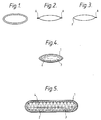
- the container may be in any form with which the operating fluid may easily be filled or diffused. That is, the container may be, as shown in Figs. 1 - 3, in the form of a flat tube, in the form of two films of which ends are heat-sealed, or in the form of one film folded and of which ends are heat-sealed. Further, the container may be in the form of a pipe or a hollow fiber.
- any form is employable as long as the vapor space is inflated due to the vaporization of the operating fluid.
- the container is in the form of a sheet (flat), very thin and flexible container may be obtained.
- the operating fluid is easily dispersed at the time of not using the heat-transferring structure and the circulation of the operating fluid is aided.
- the container of the present invention may have a variation along its longitudinal direction, that is, the shape of the cross-section or the cross-sectional area may be varied.
- the polymer film or the composite film made of a polymer material and an inorganic material which is the material for constituting the sealed container
- the polymer film or the polymer material employed herein may be any polymer such as polyesters, polyamides and polyolefins as long as it has a gas-barrier property and a compatibility with the operating fluid, i.e., insolubility to the operating fluid later described.
- the material includes plastic sheets of polyvinyl alcohols, polyesters and polyamides.
- Preferred examples of the material includes polymer films with gas-barrier property, such as polyvinilidene chloride, polyvinyl alcohols, Nylon and ethylene-vinyl alcohols.
- the polymer film or the polymer material may be employed individually, it is preferred to use a composite sheet having two or more of such films because the desired sheet properties, i.e., gas-barrier property and heat-sealing property may easily be obtained and the desired strength for operation may easily be attained.
- a composite sheet such as a laminate or a coating of a polyester with a high strength and a polyolefin with a gas-barrier property, as well as combination thereof may be employed as a material with good gas-barrier property, adhesivity and durability.
- a composite sheet of polymer films with good gas-barrier property may preferably be employed.
- a film with good gas-barrier property such as polyvinilidene chloride, polyvinyl alcohol and polyacrylonitrile and a polymer film with both good gas-barrier property and adhesivity may preferably be employed.
- a laminate of ethylene-vinyl alcohol copolymer with a good gas-barrier property and polyethylene which can easily be adhered may be employed.
- the composite sheets comprising the polymer material and the inorganic material are the sheets made of the above-mentioned polymer film to which a metal or a ceramic such as Al, ZnD 2 or TiO 2 is coated or vapor-deposited to further promote the gas-barrier property.
- a metal or a ceramic such as Al, ZnD 2 or TiO 2
- Such a vapor-deposited composite sheet may be applied not only to the above-mentioned films with a good gas-barrier property, but also to the polymer films with somewhat lower gas-barrier property.
- Examples of such polymer films include 6-Nylon, polyvinyl chloride, high density polyethylene and polyethylene terephthalate sheet.
- the composite sheets which may be employed in the present invention include, besides the laminates of the above-mentioned polymer films, those composite sheets comprising a sheet made of the above-mentioned polymer film and a coating of the above-mentioned metal or ceramic. Still further, laminates of the above-mentioned vapor-depositod films may also be employed.
- the composite sheet employed in the present invention may be in the form of a plate or a film, and usually in the form of film.
- the compositing of the film as described-above can be fully applied:
- the inorganic material in the form of particles may be admixed in the polymer and the polymer may then be shaped or spun.
- the operating fluid used in the prcsent invention is a medium which carrys heat, and one which is operable at the temperature range employable for the polymer film or polymer material is selected.
- the operating fluid is a medium which induces the gas-liquid phase conversion
- examples of the operating fluid include acetaldehyde, isopentane, ethane thiol, isopropyl chloride, pentane, methyl formate, diethylether, dichloromethane, dibromodifluoromethanc, ethyl bromide, tetramethyl silane, trichlorofluoromethane, trifluoro acetic acid anhydride, methyl fluoroacetate, t-butyl amine, methyl iodide, dimethyl sulfide and the like.
- These fluids are operable at the temperature of human body for which the flexibility is especially required.
- those substances such as methanol, acetone, ethanol, ethyl formate and water, which have a gas-liquid phase transition point at 20 - 10O°C may be operable at a lower temperature under a reduced pressure.
- mixed media of the above-mentioned media and carbon dioxide, water, acetone, ethanol or formic acid may also be used.
- simple substances or mixed media which have gas-liquid transition point between 20 - 45°C may also be used.
- Examples of these fluids include carbon disulfide/acetone, carbon disulfide/ethanol, carbon disulfide/formic acid, carbon disulfide/ethyl formate, carbon disulfide/methyl formate, carbon disulfide/methyl acetate, carbon disulfide/cyclopehtane, carbon disulfide/ethyl bromide, carbon disulfide/t-butyl alcohol, carbon disulfide/2-propanol, carbon disulfide/pentane, carbon disulfide/methanol, water/pentane, acetone/isopentane, aceton/cyclopentane, acetone/isopentane, acetone, cyclopentane, acetone/pentane, ethanol/isopentane, ethanol/isopropyl chloride, ethanol/cyclopentanc, ethanol/pentane, isopentane formate, formic acid/isopropyl chloride
- the temperature range of 20 - 45°C is the temperature range which human experiences in daily life.
- the heat-transferring structure which transfers heat under this temperature range is important for appropriately releasing heat from human body to keep the body temperature at a certain temperature.
- the operating fluid and the material of container are chosen such that the operating fluid does not corrodes the material,
- a container made of polyvinyl alcohol may preferably be selected. Many other combinations can be employed.
- a material which adsorbs or captures the operating fluid such as a foamed material, a material with fine pores and a fibrous material, as well as these materials which are treated so as to increase their adsorption
- the fibrous material to be inserted in the container includes fabrics such as woven fabrics and non-woven fabrics; specific fibers such as super fine fibers and porous fibers; and goneral fibers for clothes.
- fabrics such as woven fabrics and non-woven fabrics; specific fibers such as super fine fibers and porous fibers; and goneral fibers for clothes.
- the above-mentioned fibrous material may be a synthetic fiber such as polyesters, polyamides and polyolefin fibers.
- the spacer employed in the present invention is a _ structure for forming a vapor space with a pressure of not higher than 1 atm in the sealed container.
- a flexible material which is not crushed by the outer pressure (1 atm) and which can form a vapor space (a space with reducod pressure) under the outer pressure is selected. If such a space exists, even at a temperature lower than the boiling point at 1 atm, evaporation of the liquid and its move can be smoothly effected, so that the heat of vaporization can be taken.
- the spacer used in the present invention may be a tube or pipe made of silicone, polyester, polyamide or polyolefin, or the spacer may be substituted with a material which adsorbs or captures the operating fluid in the container.
- a material which adsorbs or captures the operating fluid in the container for example, non-woven fabrics, knits or nets made of a synthetic fiber, as well as porous material with chemical resistance such as PVDF may be employed.
- ruggedness on the inner wall of the container can serve as the spacer.
- the operating fluid is first placed in the container. Thereafter, the gas in the container is drawn from a specific portion of the container with a vacuum pump to reduce the pressure to 1 atm or less, and after attaining an appropriate inner pressure, the specific portion is scaled by, for example, heat-sealing.
- the specific portion is the portion through which air is drawn from the container after placing the fluid to attain an inner pressure of not higher than 1 atm.
- n-pentane for example, heptane boils at 36 0 C under 1 atm, but boils at 30°C if the pressure is reduced to 0.77 atm.
- the outer pressure (1 atm) is greater than the vapor pressure of pentane, it is prevented for the container to inflate and to burst.
- the flexible heat-transferring element of the present invention may be used basically at a portion at which heat is desired to be transferred, utilizing the cooling action at the vaporization region or the heating action at the condensation region.
- the heat-transferring structure of the present invention may be used not only individually but also in combination with a filament heat-generator, plane heat-generator or with a heat-accumulator at the vaporization region, or with a coolant at the condensation region.
- the heat-transferring structure of the present invention may be used in anywhere at which transfer of heat is desired.
- it may preferably be used as a part of woven fabrics, sheets, vests, bath tubs, pillows, helmets, rugs under "kotatsu", headbands, sofas, car sheets, belts, body bands, coolers for electronic products, shoes, carpets, ice sacks, gloves, dustproof clothes and hats.
- FIG. 4 An example of the present invention is shown in Fig. 4.
- a container 1 made of a ehylene-vinyl alcohol copolymer film a non-woven fabric 2 is inserted and operating fluid 3 is filled in the container and in the non-woven fabric.
- the container is made of a material which is light and flexible, so that heat can bo taken from the body effectively and without a feeling of incompatibility. Thus, it can give a cool feeling to the human body.
- a voluminous vapor space is not formed at the time of not using the structure, the volume of the structure at the time of non-using is much smaller than that of the conventional structure by which heat is transferred by the same principle. Still further, by virtue of the inserted non-woven fabric, the evaporation and circulation of the fluid can be made smoothly.
- a heat-transferring structure of the present invention was made by employing a laminate film of ethylene-vinyl alcohol copolymer and polyethylene as the material of the container, polyester non-woven fabric as the spacer and n-pentane (with boiling point of 36 0 C under 1 atm) as the operating fluid and by sealing the container after reducing the inner pressure to 450 mmHg.
Landscapes
- Engineering & Computer Science (AREA)
- Physics & Mathematics (AREA)
- Thermal Sciences (AREA)
- Mechanical Engineering (AREA)
- General Engineering & Computer Science (AREA)
- Life Sciences & Earth Sciences (AREA)
- Sustainable Development (AREA)
- Filling Or Discharging Of Gas Storage Vessels (AREA)
- Laminated Bodies (AREA)
Abstract
Structure flexible de transfert thermique dont la forme peut être modifiée relativement librement en fonction de l'utilisation. Plus particulièrement, la présente invention se rapporte à une structure flexible de transfert thermique se composant d'un fluide de travail et d'un récipient contenant le fluide de travail, caractérisée en ce que le récipient est rempli de fluide de travail lorsque la structure n'est pas en service, le récipient étant dilaté pour en accroître le volume à cause de la gazéification du fluide de travail et former un espace de vapeur à l'intérieur du récipient lorsque la structure est en service.
Applications Claiming Priority (4)
| Application Number | Priority Date | Filing Date | Title |
|---|---|---|---|
| JP29521886A JPH0721392B2 (ja) | 1986-12-11 | 1986-12-11 | 熱伝達素子 |
| JP29521986 | 1986-12-11 | ||
| JP295219/86 | 1986-12-11 | ||
| JP295218/86 | 1986-12-11 |
Publications (2)
| Publication Number | Publication Date |
|---|---|
| EP0306531A1 true EP0306531A1 (fr) | 1989-03-15 |
| EP0306531A4 EP0306531A4 (fr) | 1989-04-12 |
Family
ID=26560167
Family Applications (1)
| Application Number | Title | Priority Date | Filing Date |
|---|---|---|---|
| EP19880900093 Withdrawn EP0306531A4 (fr) | 1986-12-11 | 1987-12-11 | Structure flexible de transfert thermique et procede de production. |
Country Status (3)
| Country | Link |
|---|---|
| EP (1) | EP0306531A4 (fr) |
| KR (1) | KR890700796A (fr) |
| WO (1) | WO1988004399A1 (fr) |
Cited By (3)
| Publication number | Priority date | Publication date | Assignee | Title |
|---|---|---|---|---|
| WO2004094933A1 (fr) * | 2003-03-26 | 2004-11-04 | Intel Corporation | Caloduc comportant une paroi interieure de retenue pour composants a capillarite |
| CN100412492C (zh) * | 2004-11-29 | 2008-08-20 | 杨洪武 | 集成热管 |
| WO2011131931A3 (fr) * | 2010-04-21 | 2012-07-26 | Qinetiq Limited | Structures évaporatives, en particulier pour le refroidissement du corps |
Families Citing this family (2)
| Publication number | Priority date | Publication date | Assignee | Title |
|---|---|---|---|---|
| CN106038567A (zh) | 2010-11-08 | 2016-10-26 | 奥默罗斯公司 | 使用pde7抑制剂治疗成瘾和冲动控制障碍 |
| US9220715B2 (en) | 2010-11-08 | 2015-12-29 | Omeros Corporation | Treatment of addiction and impulse-control disorders using PDE7 inhibitors |
Family Cites Families (5)
| Publication number | Priority date | Publication date | Assignee | Title |
|---|---|---|---|---|
| US4094357A (en) * | 1976-04-09 | 1978-06-13 | Kenneth C. McCord | Heat transfer blanket |
| US4212347A (en) * | 1978-12-20 | 1980-07-15 | Thermacore, Inc. | Unfurlable heat pipe |
| EP0059581A3 (fr) * | 1981-03-04 | 1983-03-16 | National Research Development Corporation | Caloducs |
| EP0076081A3 (fr) * | 1981-09-25 | 1983-08-17 | The Secretary of State for Defence in Her Britannic Majesty's Government of the United Kingdom of Great Britain and | Caloducs |
| JPH05328840A (ja) * | 1992-06-02 | 1993-12-14 | Mitsubishi Agricult Mach Co Ltd | 挿し木苗の育成方法 |
-
1987
- 1987-12-11 EP EP19880900093 patent/EP0306531A4/fr not_active Withdrawn
- 1987-12-11 WO PCT/JP1987/000963 patent/WO1988004399A1/fr not_active Ceased
-
1988
- 1988-08-11 KR KR1019880700966A patent/KR890700796A/ko not_active Withdrawn
Cited By (9)
| Publication number | Priority date | Publication date | Assignee | Title |
|---|---|---|---|---|
| WO2004094933A1 (fr) * | 2003-03-26 | 2004-11-04 | Intel Corporation | Caloduc comportant une paroi interieure de retenue pour composants a capillarite |
| US6868898B2 (en) | 2003-03-26 | 2005-03-22 | Intel Corporation | Heat pipe having an inner retaining wall for wicking components |
| GB2411949A (en) * | 2003-03-26 | 2005-09-14 | Intel Corp | A heat pipe having an inner retaining wall for wicking components |
| GB2411949B (en) * | 2003-03-26 | 2006-07-05 | Intel Corp | A heat pipe having an inner retaining wall for wicking components |
| CN100557366C (zh) * | 2003-03-26 | 2009-11-04 | 英特尔公司 | 具有用于芯吸部件的内保持壁的热管 |
| CN100412492C (zh) * | 2004-11-29 | 2008-08-20 | 杨洪武 | 集成热管 |
| WO2011131931A3 (fr) * | 2010-04-21 | 2012-07-26 | Qinetiq Limited | Structures évaporatives, en particulier pour le refroidissement du corps |
| US9188398B2 (en) | 2010-04-21 | 2015-11-17 | Qinetiq Limited | Evaporative structures, particularly for body cooling |
| US9433246B2 (en) | 2010-04-21 | 2016-09-06 | Qinetiq Limited | Evaporative structures, particularly for body cooling |
Also Published As
| Publication number | Publication date |
|---|---|
| KR890700796A (ko) | 1989-04-27 |
| EP0306531A4 (fr) | 1989-04-12 |
| WO1988004399A1 (fr) | 1988-06-16 |
Similar Documents
| Publication | Publication Date | Title |
|---|---|---|
| US4067315A (en) | Solar heat pipe | |
| US5725049A (en) | Capillary pumped loop body heat exchanger | |
| US3642059A (en) | Heating and cooling unit | |
| US5603375A (en) | Heat transfer device | |
| US5048301A (en) | Vacuum insulated sorbent driven refrigeration device | |
| EP0306531A1 (fr) | Structure flexible de transfert thermique et procede de production | |
| PT838013E (pt) | Ebulidor-absorvedor com sorvete solido, processo para a sua fabricacao e dispositivo frigorifico que o utiliza. | |
| JP4065430B2 (ja) | 熱交換器 | |
| CN208936834U (zh) | 一种柔性平板热管结构 | |
| US20040163178A1 (en) | Thermally insulative cushion | |
| EP0215114B1 (fr) | Collecteur solaire | |
| US3719051A (en) | Transportable refrigeration system | |
| JP2904199B2 (ja) | キャピラリポンプループ用蒸発器及びその熱交換方法 | |
| JP2663775B2 (ja) | 満液式蒸発器 | |
| US5012650A (en) | Cryogen thermal storage matrix | |
| AU2008221567A1 (en) | Atmospheric water generator having a zero carbon footprint | |
| JPS6357719B2 (fr) | ||
| JPS63267890A (ja) | 柔軟な熱伝達素子 | |
| CN108917444A (zh) | 一种柔性平板热管结构 | |
| JPS63207994A (ja) | 熱循環装置 | |
| CN207831530U (zh) | 蒸发冷凝双重强化换热管 | |
| JPH01123995A (ja) | 柔軟な熱伝達素子およびその製造方法 | |
| SU1112216A1 (ru) | Теплообменный элемент | |
| JPS63311901A (ja) | 放熱シュ−ズ | |
| JP3199287B2 (ja) | 熱交換器用伝熱管 |
Legal Events
| Date | Code | Title | Description |
|---|---|---|---|
| PUAI | Public reference made under article 153(3) epc to a published international application that has entered the european phase |
Free format text: ORIGINAL CODE: 0009012 |
|
| 17P | Request for examination filed |
Effective date: 19880831 |
|
| AK | Designated contracting states |
Kind code of ref document: A1 Designated state(s): AT BE CH DE FR GB IT LI LU NL SE |
|
| A4 | Supplementary search report drawn up and despatched |
Effective date: 19890412 |
|
| STAA | Information on the status of an ep patent application or granted ep patent |
Free format text: STATUS: THE APPLICATION IS DEEMED TO BE WITHDRAWN |
|
| 18D | Application deemed to be withdrawn |
Effective date: 19890620 |