EP0306573B1 - Machine pour emballer avec un film étirable - Google Patents
Machine pour emballer avec un film étirable Download PDFInfo
- Publication number
- EP0306573B1 EP0306573B1 EP87307930A EP87307930A EP0306573B1 EP 0306573 B1 EP0306573 B1 EP 0306573B1 EP 87307930 A EP87307930 A EP 87307930A EP 87307930 A EP87307930 A EP 87307930A EP 0306573 B1 EP0306573 B1 EP 0306573B1
- Authority
- EP
- European Patent Office
- Prior art keywords
- wrapping material
- arm
- stretchable
- tension
- roller
- Prior art date
- Legal status (The legal status is an assumption and is not a legal conclusion. Google has not performed a legal analysis and makes no representation as to the accuracy of the status listed.)
- Expired
Links
- 239000000463 material Substances 0.000 claims description 131
- 230000002093 peripheral effect Effects 0.000 claims description 20
- 230000007423 decrease Effects 0.000 claims description 16
- 230000001172 regenerating effect Effects 0.000 claims description 16
- 238000013459 approach Methods 0.000 claims description 11
- 239000006249 magnetic particle Substances 0.000 claims description 2
- 230000007246 mechanism Effects 0.000 description 31
- 230000033001 locomotion Effects 0.000 description 8
- 230000004044 response Effects 0.000 description 7
- 230000001276 controlling effect Effects 0.000 description 5
- 230000009471 action Effects 0.000 description 4
- 230000008859 change Effects 0.000 description 4
- 230000003287 optical effect Effects 0.000 description 4
- 238000010276 construction Methods 0.000 description 3
- 238000006073 displacement reaction Methods 0.000 description 3
- 230000001105 regulatory effect Effects 0.000 description 3
- 230000005540 biological transmission Effects 0.000 description 2
- 238000012423 maintenance Methods 0.000 description 2
- 238000011144 upstream manufacturing Methods 0.000 description 2
- 239000013214 MOP-1 Substances 0.000 description 1
- 230000004913 activation Effects 0.000 description 1
- 230000009286 beneficial effect Effects 0.000 description 1
- 238000012937 correction Methods 0.000 description 1
- 230000003247 decreasing effect Effects 0.000 description 1
- 238000013461 design Methods 0.000 description 1
- 238000010586 diagram Methods 0.000 description 1
- 230000000694 effects Effects 0.000 description 1
- 238000000034 method Methods 0.000 description 1
- 230000008569 process Effects 0.000 description 1
Images


Classifications
-
- B—PERFORMING OPERATIONS; TRANSPORTING
- B65—CONVEYING; PACKING; STORING; HANDLING THIN OR FILAMENTARY MATERIAL
- B65B—MACHINES, APPARATUS OR DEVICES FOR, OR METHODS OF, PACKAGING ARTICLES OR MATERIALS; UNPACKING
- B65B11/00—Wrapping, e.g. partially or wholly enclosing, articles or quantities of material, in strips, sheets or blanks, of flexible material
- B65B11/04—Wrapping, e.g. partially or wholly enclosing, articles or quantities of material, in strips, sheets or blanks, of flexible material the articles being rotated
- B65B11/045—Wrapping, e.g. partially or wholly enclosing, articles or quantities of material, in strips, sheets or blanks, of flexible material the articles being rotated by rotating platforms supporting the articles
Definitions
- the present invention relates to stretch wrapping machines having prestretchers for elongating a stretchable wrapping material from its initial length as unwound from a supply roll to a controlled elongation prior to wrapping of a load located on a rotatable turntable. More particularly, the invention relates to prestretchers which utilize a single power driven roller to achieve prestretching.
- French Patent 2,281,275 to Thimon discloses a prestretching system which utilizes a pair of power driven rollers to achieve prestretching of a stretchable wrapping material prior to the wrapping of a load located on a rotatable load support.
- the speed of the downstream roller is greater than the upstream roller located closest to the supply roll to achieve stretching of the stretchable wrapping material.
- the relative velocities of the rollers controls the amount of prestretching.
- Patent 4,418,510 discloses a process similar to that disclosed in Thimon.
- a pair of driven rollers function as a prestretcher for elongating the stretch wrapping material prior to wrapping around a load disposed on a rotatable load support. The degree of elongation is controlled by the relative peripheral velocities of the pair of rollers.
- Patent 4,418,510 also discloses that the combination of a single power driven roller and a braked film supply roll may be used to perform prestretching.
- Stretching of stretchable wrapping material between the load to be wrapped and the supply roll has also been accomplished by the use of a friction brake for varying the degree of force required to unwind the stretch wrapping material during wrapping of the load which controls the degree of stretch achieved from the nominal dimension of the stretchable wrapping material as wound on the supply roll.
- a friction brake for varying the degree of force required to unwind the stretch wrapping material during wrapping of the load which controls the degree of stretch achieved from the nominal dimension of the stretchable wrapping material as wound on the supply roll.
- conventional friction brakes are difficult to control when objects with corners are being wrapped because of the cyclical variation of the wrapping speed of the stretchable wrapping material around the object as a consequence of corner passage.
- the brake is controlled by a mechanism for applying substantially constant tension to the stretchable wrapping material between the supply roll and the driven roller by the application of a constant force biased against the stretchable wrapping material and a tension sensor which senses changes in the tension between the supply roll and the driven roller to generate a control signal for controlling the brake, by a control signal generated by a diameter sensor which senses the change in the outside diameter of the supply roll occurring during stretch wrapping which is caused by the unrolling of the stretchable wrapping material or by a control signal generated by a ratio comparison of the peripheral velocity of the driven roller to the peripheral velocity of the supply roll.
- variable ratio transmission is controlled by a mechanism for applying substantially constant tension to the stretchable wrapping material between the supply roll and the driven roller by the application of a constant force biased against the stretchable wrapping material and a tension sensor which senses changes in the tension between the supply roll and the driven roller to generate a control signal for controlling the brake, by a control signal generated by a diameter sensor which senses the change in the outside diameter of the supply roll of stretchable wrapping material occurring during stretch wrapping which is caused by the unrolling of the stretchable wrapping material or by a control signal generated by a ratio comparison of the peripheral velocity of the driven roller to the peripheral velocity of the supply roll of stretchable wrapping material.
- the single power driven roller is driven by a DC motor controlled by a DC regenerative controller which isolates the prestretching mechanism from variations in the velocity of the stretchable wrapping material caused by the wrapping of objects with corners.
- an accumulating mechanism for stretchable wrapping material located between the single power driven roller and the rotatable turntable, which provides additional stretchable wrapping material during the increase in velocity of stretchable wrapping material and which takes up stretchable wrapping material during the decrease in the velocity of the stetchable wrapping material that occurs during the wrapping of loads with corners, isolates the prestretcher from the effects of the variation in velocity during stretch wrapping without requiring variation in the speed of the motor driving the driven roller.
- the accumulator is located in a mechanism for applying a constant wrapping tension during the wrapping of the load.
- the constant tension wrapping mechanism enables the precise control of the degree of additional stretching or relaxation of the stretchable wrapping material which occurs after the prestretched wrapping material leaves contact with the power driven roller.
- the prestretcher in combination with the constant tension maintaining mechanism located between the single power driven roller and the rotatable load support provides a degree of control of prestretching and stretching or relaxation between the prestretcher and the load which has heretofore only been achievable by stretch wrapping machines as disclosed in our US-A-4 590 746 which utilise a pair of power driven rollers to perform prestretching.
- the constant force applying mechanism applies a constant force to a movable element which contacts the stretchable wrapping material disposed between the rotatable holder and the driven roller which moves in a first direction when tension of the stretchable wrapping material contacting the movable element increases and which moves in a second direction when the tension of the stretchable wrapping material contacting the movable element decreases
- a control signal generator senses the movement of the movable element and generates the control signal which increases as a function of movement in the first direction and which decreases as a function of movement in the second direction.
- means for maintaining substantially constant tension is disposed between the driven roller and the rotatable turntable which controls the speed of the variable speed electric motor as a function of the velocity sensed on the stretchable wrapping material located between the driven roller and the turntable.
- the means for maintaining substantially constant tension may comprise a first arm pivotably mounted for rotation around a fixed point through a path of rotation; a tension roller rotatably mounted on the first arm at a point offset from the fixed point, the tension roller engaging the stretchable wrapping material to define a path of approach of the stretchable wrapping material between the dispensing means and the tension roller, and a path of departure of the stretchable wrapping material between the tension roller and the rotatable turntable; the first arm defining a first angle with the path of approach of the stretchable wrapping material and a second angle with the path of departure of the stretchable wrapping material, the first and second angles being substantially equal within the path of rotation and varying with rotation of the arm through the path of rotation; a second arm pivoted about the fixed point which is connected to the first arm or is part of the first arm; and a constant force applying mechanism for applying a constant force to the second arm at a point offset from the pivot point which opposes a force applied to the first arm by tension on the stretchable wrapping material in the paths of approach and departure,
- the mechanism for maintaining substantially constant tension further includes a sensor for sensing when the first arm moves past a first angular limit at a boundary of a first control zone into a second control zone within the path of rotation that is caused by an increase in the velocity of the stretchable wrapping material being wrapped around the load and for sensing when the first arm moves past a second angular limit at a boundary of the first control zone into a third control zone within the path of rotation that is caused by a decrease in the velocity of the stretchable wrapping material being wrapped around the load; and a controller coupled to the motor for rotating the driven roller to increase the speed of the motor for causing the stretchable wrapping material leaving contact with driven roller to increase in velocity in response to the means for sensing when the first arm moves past the first angular limit into the second control zone, to decrease the speed of the motor for causing stretchable wrapping material leaving contact with the driven roller to decrease in velocity in response to the means for sensing when the first arm moves past the second angular limit into the third control zone and for causing the motor to
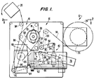
- Figure 1 is a top plan view of a first embodiment of the present invention.
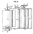
- Figure 2 is an elevational view of Figure 1.
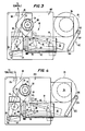
- Figure 3 is a top plan view of a second embodiment of the present invention.
- Figure 4 is a top plan view of a third embodiment of the present invention.
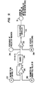
- Figure 5 is a control circuit for the brake of the first and second embodiments of the present invention.
- Figure 6 is a control circuit for the motor driving the substantially constant tension maintaining mechanism of the various embodiments of the present invention.
- Figure 7 is a diagram of vector forces during operation of the mechanism for maintaining substantially constant tension mechanism which is located downstream from the prestretcher.
- Figure 8 is an illustration of the operation of the motor controller of Figure 6 as a function of the angular position of the dancer.
- Figure 9 is a control circuit for the third embodiment of the present invention.
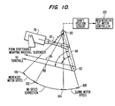
- Figure 10 is an alternative embodiment of a mechanism for producing substantially constant tension producing which may be used in the various embodiments.
- Figs. 1 and 2 illustrate a first embodiment 10 of a stretch wrapping machine in accordance with the present invention.
- the main elements of the first embodiment 10 are a supply of stretchable wrapping material 12 which supplies stretchable wrapping material 14 which is fed to a prestretching unit 16 where it is elongated by a drawing action.
- the prestretching unit 16 may elastically or inelastically stretch the stretchable wrapping material 14.
- the stretchable wrapping material is fed from the prestretching unit 16, where it is elongated by a set amount, to a mechanism 18 for producing substantially constant wrapping tension which wraps the prestretched stretchable wrapping material to a load positioned on a rotatable turntable 20 under substantially constant tension.
- a rotatable turntable 20 may be any mechanism for producing relative rotary motion between a load and the stretchable wrapping material. These mechanisms include a turntable rotated by motor and a mechanism which has a stationary load support and a supply of stretchable wrapping material which rotates around the load support to accomplish wrapping.
- the supply 12 has a chuck 22 for holding a roll 24 of stretchable wrapping material to be used in stretch wrapping loads.
- the chuck 22 has an upper mandrel 26 which is rotatably mounted in a horizontally disposed support plate 28 by a bushing.
- a lower mandrel 32 is rotatably mounted within a horizontally extending arm 34 by a bearing located within electrically powered brake 36.
- the upper mandrel 26 is axially displaceable upward and downward directions to permit the supply roll of stretchable wrapping material 24 to be lowered down into contact with the lower mandrel 32. Thereafter, the upper mandrel 26 is lowered to engage the supply roll of stretchable wrapping material 24.
- the electrically powered brake 36 is coupled to the shaft 37 which is coupled to the lower mandrel 32 to apply a controlled braking action.
- a control signal which is generated in a manner described infra , controls the magnitude of the braking action applied by brake 36.
- the preferred type of brake 36 is a magnetic particle brake which is a model EPB-120-8-90-14 manufactured by Electroid Company, Fade Road, Springfield, New Jersey 07081.
- the aforementioned model of brake 36 has the characteristic of producing a substantially constant braking force from a complete stop up through high speeds of rotation.
- the control circuit for the brake 36 is described, infra , in conjuction with Fig. 5.
- the brake 36 may be implemented by a DC motor which is controlled by a regenerative controller.
- DC motors controlled by regenerative controllers are commercially available.
- a DC motor which is controlled by a regenerative controller can function as a brake for speeds of rotation caused by a load rotating above the rotational speed at which the motor is set to run by the regenerative controller.
- brake also covers a motor controlled by a regenerative controller.
- the prestretching unit 16 has a single driven roller 38 rotatably mounted in horizontal support plate 28 by bearing 74 and in horizontal support plate 34 by a bushing.
- the driven roller 38 is driven by a motor which is controlled by the motor control circuit, described, infra , in conjunction with Fig. 6, to draw stretchable wrapping material 14 off of the supply roll 24 with substantially constant tension.
- a dancer 42 applies substantially constant tension to the stretchable wrapping material and senses changes in tension in the stretch wrapping material located between idler roller 44 and the power driven roller 38.
- the tension of the stretchable wrapping material located between supply roll 24 and driven roller 38 increases linearly with the decrease in the outside diameter of the stretchable wrapping material 14 when the braking force applied by brake 36 is constant.
- a constant tension applied to the stretchable wrapping material 14 located between supply roll 24 and driver roller 38 produces constant prestretching.
- the tension is maintained substantially constant by decreasing the braking force of brake 36 linearly with the decrease in outside diameter of the supply roll of stretchable wrapping material 24.
- the dancer 42 includes a constant force producing mechanism 52 which has an extensible arm rotatably connected to one end of arm 48 having idler roller 46 mounted at the other end.
- the arm 48 is pivoted about point 50.
- the constant force producing mechanism 52 is preferably an air cylinder having a self-relieving type of air regulator. Adjustment of the regulated air pressure adjusts the amount of prestretching by varying the tension applied to the stretchable wrapping material by the constant force producing mechanism 52. Small changes in the tension of the stretchable wrapping material which is contacting the idler roller 46 cause an upward or downward displacement of the idler roller which produces a corresponding opposite displacement of the extensible rod 54. Movement of the idler roller 46 in response to small changes in tension occurs until a force equilibrium is again achieved as a consequence of the variation of the braking force applied by brake 36 in a manner described, infra , in conjunction with Fig. 5.
- Substantially constant tension is applied to the stretchable wrapping material by the dancer 42 as a consequence of the geometry of arm 48 and the constant force producing element 52 and the sections of stretchable wrapping material 56 and 58 being substantially parallel.
- the torque applied to arm 48 by the extensible arm 54 is substantially equal to and opposite to the torque applied by the tension of sections 56 and 58 as long as the angle between arm 48 and extensible arm 54 is substantially equal to the angles between the sections 56 and 58 and arm 48.
- the force applied to arm 48 is substantially constant for the full range of extension of extensible arm 54.
- the section of stretchable wrapping material 56 approaching idler roller 46 is substantially parallel to the section of stretchable wrapping material 58 leaving the idler roller.
- a shaft 60 (Fig. 2) is attached to the arm 48 which rotates about the pivot point 50.
- the shaft 60 is attached to a potentiometer or equivalent (illustrated in Fig. 5 as 134) for producing a control signal for brake 36 which is a function of the rotary position of the arm 48.
- the output signal produced by the potentiometer 134 or equivalent varies linearly with changes in tension in sections 56 and 58 as a consequence of the unrolling of the roll of stretchable wrapping material 24 and is used as the control signal for the brake 36.
- the driven roller 38 of the constant tension maintaining mechanism 18 is rotated by a variable speed electric motor 62 through a power train comprised of transmission 64 which drives sprocket 66, chain 68 and sprocket 70.
- the present invention achieves both prestretching and constant tension wrapping by powered drive of driven roller 38 from the single motor 62.
- the driven roller 38 is connected to a shaft 72 which is connected to sprocket 70 and rotatably supported by bearing 74 mounted in horizontal support plate 28.
- the dancer 76 has a geometry producing a torque acting through fixed pivot point 90 caused by the tension on the stretchable wrapping material which equals, opposes and varies directly with the torque acting through the pivot point 90 caused by a constant force producing mechanism 78 so that the wrapping tension does not vary with changes of position of the dancer.
- the constant force producing mechanism 78 has an air cylinder having a self-relieving type air regulator which produces a constant force which is applied to linkage 80. While the tension is maintained constant during a stretch wrapping operation, the tension can be varied from one operation to the next by regulating or adjusting the air pressure to the air regulator of the air cylinder itself or the air cylinder position with respect to tension roller 38.
- the linkage consists of extensible rod 82 and an L-shaped member 84 having connected sections 86 and 88.
- the L-shaped member 84 is pivotably attached to the extensible member 82.
- the L-shaped member 84 is pivoted about fixed point 90.
- Tension roller 92 is carried on the end of the section 88 opposite pivot point 90.
- the spacing of the idler roller 92 with respect to the power driven roller 38 and fixed idler roller 94 causes the section of stretchable wrapping material in the path of approach 96 to the tension roller 92 and the section of stretchable wrapping material in the path of departure 98 moving away from the tension roller 92 to be substantially parallel during movement of the L-shaped member 84 in response to differential changes in tension in the stretchable wrapping material being wrapped around a load located on the turntable 20 as a consequence of corner passage of multisided loads.
- the tension roller 92 has been omitted from Fig. 2.
- the angles a, b and c, as illustrated in Figs. 7 and 8, are substantially equal. While the preferred manner of controlling the path of departure 98 so that angle c of Figs.
- the combination of the substantial parallel sections of stretchable wrapping material defined between the path of approach 96 and the path of departure 98, which causes angles b and c to be substantially equal, the angle a being substantially equal to angles b and c and the application of a constant force opposing the tension of the stretchable wrapping material in the path of approach 96 and the path of departure 98 produces substantially constant tension stretch wrapping.
- the tension on the stretchable wrapping material in the path of approach 96 and path of departure 98 acting through pivot point 90 does not substantially vary between the angular limits 106 and 108 illustrated in Fig. 8 because of the geometry involving angles a, b and c.
- the torque applied by the constant force producing air cylinder 78, as applied by the extensible rod 82 and first section 86 of the L-shaped member 84 through pivot point 90, is substantially equal to and opposes the torque applied by the tension on the stretchable wrapping material acting through the second section 88 of the L-shaped member 84 independent of the rotary position of the dancer 76 between the angular limits 106 and 108.
- the torques acting through pivot point 90 are analyzed mathematically as follows in conjunction with Fig. 7. As illustrated, the tension of the stretch wrapping material in both path of approach 96 and path of departure 98 acts against the tension roller 92 to bias the section 88 to rotate clockwise.
- Equation (1) equals equation no. (2).
- T cos (90°-b) (length of section 88) + T cos (90°-c) (length of section 88) F cos (90°-a) (length of section 88).
- the tension T is substantially constant between points 106 and 108, where angles a, b and c are substantially equal.
- Fig. 6 illustrates a motor controller 120 of the motor 62.
- Cam 106 which is mounted on the end of section 88 of the L-shaped member 84 at pivot point 90, controls the closure microswitches 112-118.
- the microswitch 112 is closed when the section 88 rotates counterclockwise past angular limit 104 (Fig. 8) to slow down the rotation of the driven roller 38 to reduce the rate of supply of stretchable wrapping material being fed to the constant tension maintaining mechanism 18 which causes the section 88 to rotate clockwise past angular limit 104 within the zone where no motor speed control is produced by the motor controller 120.
- the microswitch 114 is closed when the stretchable wrapping material breaks which causes the activation of an emergency stop dynamic braking circuit.
- the emergency stop dynamic braking circuit When activated, the emergency stop dynamic braking circuit instantaneously stops the motor 62 which drives the driven roller 38.
- the microswitch 116 is closed when the section 88 rotates clockwise past angular limit 102 to speed up the rotation of the driven roller 38 to increase the rate of supply of stretchable wrapping being fed to the constant tension maintaining mechanism 18 which causes the section 88 to rotate counterclockwise past angular limit 102 within the zone where no speed control is produced by motor controller 120.
- the microswitch 118 is closed manually when the dancer 76 is pushed against the resistance of a spring (not illustrated) to run the driven roller 38 at a slow speed used only during threading of the stretchable wrapping material.
- the regenerative controller 122 may be provided with a speed controller (not illustrated) which permits manual control of the speed of the driven roller 38 to match the demand for the stretchable wrapping material by the load being wrapped on the turntable 20 with the prestretched stretchable wrapping material being provided by the prestretcher 16.
- microswitches 112-116 may be replaced with any known position sensing mechanism.
- models 8200 UTS and LP 8200 UTS of the assignee's stretch wrapping machines sold under the trademark UNITENSION® use an optical sensor in place of the above-referenced microswitches.
- the motor controller 120 may be any known system for controlling the motor 62 for driving the power driven roller 38.
- the motor controller 120 includes a motor operated potentiometer (MOP) 121 which may be a model SS MOP-1 manufactured by Precision D Series, Inc., 63 Nicholas Road, Framingham, Massachusetts, and a regenerative DC motor controller 122 which may be a model RG 8 manufactured by Southcon Corporation, 3608 Rozzells Ferry Road, Charlotte, North Carolina.
- MOP motor operated potentiometer
- the output of the regenerative DC motor controller 122 is applied to motor 62 which drives the driven roller 38 as described, supra , in conjunction with Fig. 1.
- the function of the regenerative DC motor controller 122 is to maintain the output shaft speed of the motor 62 constant independent of torque.
- a DC motor controlled by a regenerative controller functions as a brake to the motor load when the motor is being driven by the load at a speed higher than the rated speed of the controller.
- the function of the motor operated potentiometer 121 or equivalent is upon the closure of microswitch 112 and microswitch 116 to vary the resistance of the potentiometer to produce a control signal respectively to increase and to decrease the velocity of the motor driving the power driven roller 38.
- the output signal which is applied from the motor operated potentiometer 121 to the regenerative DC motor controller 122 is maintained at a constant potential as long as the idler roller stays within the section labelled "no speed correction" as illustrated in Fig. 8.
- motor controllers 120 may be used in place of the specific embodiment described, supra , in Fig. 6.
- an optical position sensing system performs the functions of the microswitches 112 & 116 and motor operated potentiometer 121.
- switches 114 & 118 are present and the generation of the variable control signal is done by an optical sensor which is not subject to mechanical wear.
- other types of long life potentiometers or equivalents may be used in place of the motor operated potentiometer 121. Any known regenerative DC motor controller may be used.
- the combination of the prestretching unit 16 upstream from the constant tension maintaining mechanism 18 produces precise control of the prestretching of the stretchable wrapping material 14 independent of cyclical variations in the velocity of the stretchable wrapping material being wrapped around a load located on the turntable 20 as a consequence of wrapping of multisided loads.
- the accumulating function which is inherently performed by the dancer 76 between the angular limits 102 and 104, supplies additional stretchable wrapping material or takes up stretchable wrapping material during the wrapping of loads with corners without any variation in the speed at which the motor driven roller 38 is driven.
- Fig. 5 illustrates the electrical control circuit of the brake 36 of Figs. 1 and 2.
- a source of alternating current 124 is applied to a full wave rectifier 126 for producing a DC output voltage on terminals 128 and 130.
- a master control potentiometer 132 is coupled to the terminals 128 and 130. The function of the master control potentiometer 132 is to permit adjustment of the full range of braking force which may be applied by the brake 36 to vary the amount of prestretching.
- Potentiometer 134 is activated by rotation of the shaft 60 to which the constant tension dancer 42 is attached. In order to obtain sufficient dynamic range of potentiometer 134, it is desirable to gear drive the potentiometer from the rotation of the constant tension dancer 42 by a ratio such as 10:1.
- the gear drive has been omitted from Fig. 2 since its design is conventional.
- Other known ways of obtaining an increased dynamic range in the generation of the control signal for the brake 36 in response to the rotation of the shaft 60 attached to the constant dancer 42 may be used.
- An optical sensor of the type used in the aforementioned models 8200 UTS and LP 8200 UTS of stretch wrapping machines sold under the trademark UNITENSION® may be used in place of potentiometer 134.
- FIG. 3 illustrates a second embodiment 190 of the present invention.
- the second embodiment differs from the fist embodiment in that the control signal used for varying the braking force of brake 36 is generated by a diameter sensor 192.
- the diameter sensor 192 has a pivotably mounted arm 194 which is spring biased (not illustrated) to cause contact between an idler roller 196 on the periphery of the roll of stretch wrapping material 24.
- the shaft 198 is coupled to potentiometer 134 of Figure 13.
- the control signal generated by the potentiometer 134 causes a corresponding decrease in the braking force applied by brake 36 to produce a constant ratio between the peripheral velocity of the driven roller 38 and the peripheral velocity of the roll of stretchable wrapping material 24.
- the constant tension mechanism 18 functions to isolate changes in the velocity of stretchable wrapping material occurring during the wrapping of a load on the turntable 20 from the prestretcher 16 which produces a constant controllable prestretching.
- Figures 4 and 9 illustrates a third embodiment 230 of the present invention. Like reference numerals in Figures 3 and 4 identify identical parts.
- a velocity sensor 232 which may be a conventional tachometer, has a rotatably mounted roller 234 which senses the peripheral velocity of the roll of stretchable wrapping material 24 by riding in contact therewith.
- the rotation of the shaft 236 of roller 234 rotates a velocity signal generator (not illustrated) which produces an output signal.
- a velocity sensor (element 240 in Figure 9), which also may be a conventional tachometer, is connected to the shaft driving driven roller 38 which senses the peripheral velocity of the driven roller.
- Figure 9 illustrates the control circuit for the brake 36 of the embodiment illustrated in Figure 4.
- the function of the control circuit is to maintain a constant ratio of the peripheral velocity of the driven roller 38 to the peripheral velocity of the supply roll 24.
- the output signal T1 from the tachometer 232 and the output signal T2 from the tachometer 240 are respectively applied to the inverting and noninverting inputs of a differential amplifier 242 to compute the quantity T2-T1.
- the output of differential amplifier 242 is applied to a divider 244 to which is also applied the output signal from the tachometer 232 to compute the quantity which is a function of the percentage of prestretch.
- the output from the divider 244 is applied to indicator 246 which displays the percentage of prestretch which is useful for users of the stretch wrapping machine.
- Differential amplifier 250 compares the quantity with the set amount of desired prestretch from potentiometer 248 which produces an output signal of zero when the system is in balance (i.e. prestretching at the desired rate) and positive or negative outputs depending on which way the system is out of balance.
- the output signal from the differential amplifier 250 is applied to brake controller 252 which is an amplifier designed to power the brake 36.
- brake controller 252 which is an amplifier designed to power the brake 36.
- the brake 36 is activated to either increase or decrease the braking force to maintain the constant ratio of peripheral velocity of the driven roller 38 to the peripheral velocity of the roll of stretchable wrapping material 24.
- the amount of prestretching (i.e. the percentage of elongation past the nominal length of the stretchable wrapping material from the roll of stretchable wrapping material 24) is set in the various embodiments as follows.
- the first embodiment sets the amount of prestretching by the setting of the regulated air supply associated with the constant force producing element 52.
- the second embodiment sets the amount of prestretching by the setting of a potentiometer which controls the ratio of the peripheral velocity of the driven roller 38 to the peripheral velocity of the supply roll 24.
- the third embodiment controls the amount of prestretching by setting the potentiometer 248.
- Figure 10 illustrates an alternative embodiment of the mechanism for producing substantially constant wrapping tension to that illustrated in Figure 8.
- Like reference numerals illustrate like parts in Figure 8 and 10.
- the difference between the embodiments of Figure 8 and 10 is that the constant force producing mechanism is attached directly to the arm 88 to counter the force applied to the tension roller 92 by stretchable wrapping material.
- the theory of operation for both embodiments is identical.
- the length of the arm between the attachment point to arm 88 and the pivot point of arm 88 is treated as the length of the section 86 in the analysis in Figure 7.
- the pivot point 90 may be located intermediate the ends of the arm 88 with the extensible arm 80 pivotably attached to the end of arm 88 opposite tension roller 92 as with the dancer 42 of the first embodiment.
Landscapes
- Engineering & Computer Science (AREA)
- Mechanical Engineering (AREA)
- Basic Packing Technique (AREA)
- Controlling Rewinding, Feeding, Winding, Or Abnormalities Of Webs (AREA)
Claims (9)
- Machine d'emballage pour emballer une charge placée sur un plateau tournant (20), une traction d'enveloppement constante étant exercée, avec une matière d'emballage étirable (14) qui a été pré-étirée avant d'être enroulée autour de la charge et qui est issue d'un support rotatif (22) servant à retenir un rouleau (24) de matière d'emballage étirable et fournissant la matière d'emballage à enrouler autour de la charge, la machine comprenant un moyen d'amenage (38) disposé entre le rouleau (24) de matière d'emballage étirable et le plateau tournant (20), le moyen d'amenage (38) étant conçu pour venir au contact de la matière d'emballage étirable (14) pour appliquer à la matière d'emballage étirable un force provoquant un préétirage de la matière d'emballage étirable afin de commander la vitesse d'amenage de la matière d'emballage étirable en train d'être acheminée jusqu'à la charge pour maintenir une traction d'enveloppement constante; un moteur électrique (62) à vitesse variable pour entraîner le moyen d'amenage (38); et un moyen de traction constante (76) disposé entre le moyen d'amenage (38) et le plateau tournant (20) pour maintenir une traction d'enveloppement constante (18) sur la matière d'emballage étirable (14) en train d'être enroulée autour de la charge, ledit moyen de traction constante (76) commandant la vitesse du moteur électrique (62) à vitesse variable en fonction de la vitesse de la matière d'emballage étirable en train d'être acheminée à la charge pour maintenir une traction d'enveloppement constante; caractérisée en ce que le moyen d'amenage comporte un unique cylindre mené (38), en ce qu'un moyen de freinage réglable (36) est couplé au support rotatif (22) pour appliquer une force de freinage au support conformément à un signal de commande de frein appliqué à celui-ci pour amener la matière d'emballage disposée sur le support rotatif à être retenue en fonction du signal de commande; et en ce qu'un mécanisme de commande (232 à 252) est prévu pour produire le signal de freinage en fonction de la vitesse du cylindre mené (38), de la vitesse périphérique du rouleau (24) de matière d'emballage étirable (14) et d'une valeur de pré-étirage prédéterminée.
- Machine d'emballage selon la revendication 1, dans laquelle le mécanisme de commande comprend: un moyen (244) pour calculer un rapport qui est une fonction de la vitesse périphérique du cylindre mené (38) divisée par une fonction de la vitesse périphérique du rouleau (24) de matière d'emballage étirable; et un moyen (250) couplé au moyen de calcul (244) et au moyen de prédétermination de la valeur de pré-étirage afin de comparer le rapport avec la valeur de pré-étirage prédéterminée pour produire le signal de commande, le signal de commande étant nul quand le rapport et la valeur prédéterminée sont égaux et variant avec le signe de la différence entre le rapport et la valeur de pré-étirage prédéterminée.
- Machine d'emballage selon la revendication 2, dans lequel le moyen de calcul (244) calcule la quantité

- Machine d'emballage selon l'une quelconque des revendications précédentes, dans laquelle ledit moyen de freinage est un moteur électrique commandé par un mécanisme à récupération.
- Machine d'emballage selon l'une quelconque des revendications 1 à 3, dans laquelle le moyen de freinage (36) est un frein à particules magnétiques.
- Machine d'emballage selon l'une quelconque des revendications précédentes, dans laquelle ledit moyen pour maintenir une traction sensiblement constante comprend: un premier bras (88) articulé pour tourner autour d'un point fixe (90) en effectuant un parcours de rotation; un premier cylindre (92) monté de façon à pouvoir tourner sur le premier bras (88) en un point décalé du point fixe (90), le premier cylindre (92) venant contre la matière d'emballage étirable (14) pour définir un parcours d'approche de la matière d'emballage entre le cylindre mené (38) et le premier cylindre (92); un second cylindre (94) monté de façon à pouvoir tourner en un point entre le premier cylindre (92) et le plateau tournant (20), qui vient contre la matière d'emballage étirable (14) pendant l'enveloppement de la charge et qui définit un parcours d'éloignement de la matière d'emballage étirable entre le premier cylindre (92) et le second cylindre (94), le premier bras (88) définissant un premier angle (b) avec le parcours d'approche de la matière d'emballage étirable (14) et un second angle (c) avec le parcours d'éloignement de la matière d'emballage étirable, les premier et second angles étant sensiblement égaux dans le parcours de rotation et variant au fur et à mesure de la rotation du bras (88) sur le parcours de rotation; un second bras (86) articulé autour du point fixe (90) qui est relié au premier bras (88); et un moyen (78) pour appliquer au second bras (86), en un point décalé du point de pivotement (90), une force constante qui s'oppose à une force appliquée au premier bras (88) par la traction de la matière d'emballage (14) sur les parcours d'approche et d'éloignement, le second bras (86) et le moyen (78) pour appliquer une force constante définissant un troisième angle (a) sensiblement égal aux premier et second angles (b,c) sur le parcours de rotation du premier arbre (88).
- Machine d'emballage selon la revendication 6, dans laquelle le premier bras (88) a un axe longitudinal non parallèle à l'axe longitudinal du second bras (86).
- Machine d'emballage selon la revendication 6 ou 7, comportant un moyen (121) pour détecter l'instant où le premier bras (88) dépasse une première limite angulaire (102) en passant d'une première zone de commande à une seconde zone de commande sur le parcours de rotation sous l'action d'une augmentation de la vitesse de la matière d'emballage étirable (14) en train de s'enrouler autour de la charge; un moyen (121) pour détecter l'instant où le premier bras dépasse une seconde limite angulaire (104) en passant de la première zone de commande à une troisième zone de commande sur le parcours de rotation sous l'action d'une baisse de la vitesse de la matière d'emballage étirable en train de s'enrouler autour de la charge; le moyen de commande (120) du moteur électrique (62) à vitesse variable faisant augmenter la vitesse de rotation du moteur (62) entraînant le cylindre mené (38) quand le premier bras dépasse la première limite angulaire (102) en entrant dans la seconde zone de commande, faisant baisser la vitesse de rotation du moteur (62) entraînant le cylindre mené (38) quand le premier bras (88) dépasse la seconde limite angulaire (104) en entrant dans la troisième zone de commande et maintient sensiblement constante la vitesse de rotation du moteur (62) entraînant le cylindre mené (38) tant que le premier bras se trouve dans la première zone.
- Machine d'emballage selon la revendication 8, dans laquelle le cylindre mené (38) fait avancer la matière d'emballage étirable à une vitesse croissante tant que le premier bras (88) se trouve dans la seconde zone de commande et fait avancer la matière d'emballage étirable à une vitesse décroissante tant que le premier bras (88) se trouve dans la troisième zone de commande.
Priority Applications (2)
| Application Number | Priority Date | Filing Date | Title |
|---|---|---|---|
| AT87307930T ATE75680T1 (de) | 1987-09-08 | 1987-09-08 | Maschine zum einwickeln mittels dehnfaehiger folie. |
| DE8787307930T DE3778895D1 (de) | 1987-09-08 | 1987-09-08 | Maschine zum einwickeln mittels dehnfaehiger folie. |
Applications Claiming Priority (1)
| Application Number | Priority Date | Filing Date | Title |
|---|---|---|---|
| US06/374,741 US4590746A (en) | 1981-09-30 | 1982-05-04 | Constant tension stretch wrapping machine |
Publications (2)
| Publication Number | Publication Date |
|---|---|
| EP0306573A1 EP0306573A1 (fr) | 1989-03-15 |
| EP0306573B1 true EP0306573B1 (fr) | 1992-05-06 |
Family
ID=23478037
Family Applications (1)
| Application Number | Title | Priority Date | Filing Date |
|---|---|---|---|
| EP87307930A Expired EP0306573B1 (fr) | 1982-05-04 | 1987-09-08 | Machine pour emballer avec un film étirable |
Country Status (3)
| Country | Link |
|---|---|
| US (1) | US4590746A (fr) |
| EP (1) | EP0306573B1 (fr) |
| AU (1) | AU599140B2 (fr) |
Families Citing this family (59)
| Publication number | Priority date | Publication date | Assignee | Title |
|---|---|---|---|---|
| US4862678A (en) * | 1981-09-30 | 1989-09-05 | International Packaging Machines, Inc. | Constant tension stretch wrapping machine |
| US4590746A (en) * | 1981-09-30 | 1986-05-27 | International Packaging Machines, Inc. | Constant tension stretch wrapping machine |
| US4840006A (en) * | 1981-09-30 | 1989-06-20 | International Packaging Machines, Inc. | Stretch wrapping machine |
| US4693049A (en) * | 1982-05-04 | 1987-09-15 | International Packaging Machines, Inc. | Stretch wrapping machine |
| US4706443A (en) * | 1982-05-04 | 1987-11-17 | International Packaging Machines, Inc. | Constant tension stretch wrapping machine |
| US4866909A (en) * | 1985-12-04 | 1989-09-19 | Lantech, Inc. | High tensile wrapping process |
| US4953336A (en) * | 1984-02-23 | 1990-09-04 | Lantech, Inc. | High tensile wrapping apparatus |
| US4912911A (en) * | 1986-10-13 | 1990-04-03 | G.D. Engineering Pty. Limited | Machine for stretch wrapping of large reels of paper and other materials |
| US5114012A (en) * | 1987-03-04 | 1992-05-19 | Wta Inc. | Interleaved spiral wrapping of foam product and stretch film for packaging carbonless paper rolls |
| US4884385A (en) * | 1987-03-04 | 1989-12-05 | Appleton Papers Inc. | Interleaved spiral wrapping of foam product and stretch film for packaging carbonless paper rolls |
| US5007538A (en) * | 1987-03-04 | 1991-04-16 | Appleton Papers Inc. | Interleaved spiral wrapping of foam product and stretch film for packaging carbonless paper rolls |
| FI82011C (fi) * | 1989-01-04 | 1991-01-10 | Pesmel Insinoeoeritoimisto | Foerfarande och anordning foer svepning av plastfolie runt en vara. |
| US4991381A (en) * | 1989-06-07 | 1991-02-12 | Liberty Industries | Stretch wrapped braking apparatus |
| FR2650556B1 (fr) * | 1989-08-02 | 1991-12-13 | Newtec Int | Procede et machine de banderolage d'une charge palettisee |
| FR2650555B1 (fr) * | 1989-08-02 | 1991-12-13 | Newtec Int | Procede et machine pour deposer une bande de film de facon helicoidale sur les faces verticales d'une charge palettisee |
| DE69003510D1 (de) * | 1989-11-03 | 1993-10-28 | Kverneland Underhaug A S Naerb | Halterung für eine Folien-Spende-Spule. |
| US5174096A (en) * | 1990-10-05 | 1992-12-29 | Ishida Scales Mfg. Co., Ltd. | Form-fill-seal type packaging machine |
| DE19542618C2 (de) * | 1995-11-15 | 2001-05-31 | Friatec Rpp Gmbh System Altvat | Folienwickelvorrichtung |
| US5836140A (en) * | 1996-11-13 | 1998-11-17 | Lantech, Inc. | Wrapping a load while controlling wrap tension |
| US5794418A (en) * | 1997-07-21 | 1998-08-18 | Lai; Robert | Pallet stretch wrapping machine |
| FI105666B (fi) * | 1998-02-11 | 2000-09-29 | Haloila M Oy Ab | Käärintälaite |
| US6082081A (en) * | 1998-07-10 | 2000-07-04 | Mucha; Jacek | Powered prestretched film delivery apparatus |
| FI109113B (fi) * | 2000-02-17 | 2002-05-31 | Haloila M Oy Ab | Käärintälaite |
| US6748718B2 (en) * | 2001-11-01 | 2004-06-15 | Lantech, Inc. | Method and apparatus for wrapping a load |
| ITMI20012648A1 (it) * | 2001-12-13 | 2003-06-13 | Sipak S R L | Dispositivo di erogazione per fasciapallet a controllo meccanico e fasciapallet ottenuto con tale dispositivo |
| CA2385370C (fr) * | 2002-05-07 | 2006-07-04 | Brian Arthur Gooding | Applicateur de film etirable sur marchandises palettisees |
| US7028940B2 (en) * | 2002-10-25 | 2006-04-18 | The Procter & Gamble Company | Apparatus for unwinding rolls of web material |
| US7392960B2 (en) * | 2002-10-25 | 2008-07-01 | The Procter & Gamble Company | Method for unwinding rolls of web material |
| US7568327B2 (en) | 2003-01-31 | 2009-08-04 | Lantech.Com, Llc | Method and apparatus for securing a load to a pallet with a roped film web |
| ITBO20030436A1 (it) * | 2003-07-22 | 2005-01-23 | Aetna Group Spa | Apparecchiatura per l'avvolgimento di gruppi di prodotti. |
| FI116669B (fi) * | 2003-09-05 | 2006-01-31 | Haloila M Oy Ab | Käärintäkone |
| US7707801B2 (en) | 2005-04-08 | 2010-05-04 | Lantech.Com, Llc | Method for dispensing a predetermined amount of film relative to load girth |
| AU2007221338A1 (en) | 2006-02-23 | 2007-09-07 | Lantech.Com, Llc | Method and apparatus for securing a load to a pallet with a roped film web |
| ITMO20060221A1 (it) | 2006-07-07 | 2008-01-08 | Aetna Group Spa | Macchina avvolgitrice e metodi di avvolgimento |
| CN101631661B (zh) * | 2007-06-25 | 2012-03-14 | 夏普株式会社 | 烧制装置 |
| CA2640944A1 (fr) * | 2007-10-12 | 2009-04-12 | Cousins Packaging Inc. | Chariot pour machine d'emballage sous film etirable |
| US9908648B2 (en) * | 2008-01-07 | 2018-03-06 | Lantech.Com, Llc | Demand based wrapping |
| AU2009204214B2 (en) * | 2008-01-07 | 2014-05-22 | Lantech.Com, Llc | Electronic control of metered film dispensing in a wrapping apparatus |
| US20090235617A1 (en) * | 2008-03-24 | 2009-09-24 | Moore Philip R | Wrapping apparatus having top loading and threading film dispenser |
| US20110067364A1 (en) * | 2009-09-22 | 2011-03-24 | Cousins Neil G | Carriage For A Stretch Wrapping Machine |
| DE102009052462A1 (de) * | 2009-11-09 | 2011-05-12 | Robert Bosch Gmbh | Verfahren zum Betreiben einer Wicklereinrichtung |
| US20110179752A1 (en) * | 2010-01-22 | 2011-07-28 | Lantech.Com, Llc. | Demand throttle methods and apparatuses |
| US8356456B2 (en) * | 2010-03-04 | 2013-01-22 | Douglas Machine Inc. | Apparatus for adjustable wrapping |
| CA2814398C (fr) | 2010-10-29 | 2018-10-23 | Lantech.Com, Llc | Donnees d'enveloppement generees par une machine |
| US9932137B2 (en) | 2012-10-25 | 2018-04-03 | Lantech.Com, Llc | Corner geometry-based wrapping |
| CA2889570C (fr) | 2012-10-25 | 2020-10-27 | Lantech.Com, Llc | Enveloppement base sur un angle de rotation |
| EP2917114B1 (fr) | 2012-10-25 | 2019-12-25 | Lantech.Com, Llc | Enveloppement basé sur une circonférence effective |
| EP3461754B1 (fr) | 2013-02-13 | 2020-04-29 | Lantech.Com LLC | Profilage de matériau d'emballage pour un emballage à base de force de confinement |
| US9896229B1 (en) | 2013-08-29 | 2018-02-20 | Top Tier, Llc | Stretch wrapping apparatus and method |
| SMT202400137T1 (it) | 2014-01-14 | 2024-05-14 | Lantech Com Llc | Regolazione dinamica del parametro di forza di avvolgimento in risposta a forza di avvolgimento monitorata e/o per la riduzione di rottura della pellicola |
| US10926906B2 (en) | 2014-10-07 | 2021-02-23 | Lantech.Com, Llc | Load stability-based wrapping |
| FI20155083A7 (fi) * | 2015-02-09 | 2016-08-10 | Signode Ind Group Llc | Menetelmä muovikalvon käärimiseksi kuorman päälle sekä käärintäkone |
| US10358245B2 (en) * | 2015-09-25 | 2019-07-23 | Paul Kurt Riemenschneider, III | System and method of applying stretch film to a load |
| WO2017053603A1 (fr) | 2015-09-25 | 2017-03-30 | Lantech.Com, Llc | Machine d'emballage sous film étirable à établissement de profil de charge automatique |
| US11667416B2 (en) | 2017-09-22 | 2023-06-06 | Lantech.Com, Llc | Load wrapping apparatus wrap profiles with controlled wrap cycle interruptions |
| WO2020033306A1 (fr) | 2018-08-06 | 2020-02-13 | Lantech.Com, Llc | Emballeuse sous film étirable avec contrôle de débit de distribution par ajustement de courbe |
| WO2021050420A1 (fr) | 2019-09-09 | 2021-03-18 | Lantech.Com, Llc | Emballeuse sous film rétractable à contrôle de la vitesse de distribution basé sur la vitesse détectée du matériau d'emballage distribué et la géométrie prédite de la charge |
| EP4031455A4 (fr) | 2019-09-19 | 2024-04-03 | Lantech.Com, Llc | Classement de matériaux d'emballage et/ou profils d'usine |
| IT202200012041A1 (it) * | 2022-06-07 | 2023-12-07 | Sotemapack S P A | Apparato di svolgimento, macchina e metodo per avvolgere un carico con un film |
Family Cites Families (18)
| Publication number | Priority date | Publication date | Assignee | Title |
|---|---|---|---|---|
| CA544917A (fr) * | 1957-08-13 | L. Jacoby Harry | Machine a envelopper des rouleaux en spirale | |
| US852337A (en) * | 1906-04-13 | 1907-04-30 | Nat Wood Pipe Company | Pipe-winding machine |
| US2285654A (en) * | 1941-04-30 | 1942-06-09 | Westinghouse Electric & Mfg Co | Tension regulator |
| US2544467A (en) * | 1947-01-31 | 1951-03-06 | Aluminum Co Of America | Tension control system |
| FR2281275A1 (fr) * | 1974-08-08 | 1976-03-05 | Thimon | Procede et dispositif d'emballage de charges au moyen d'un film de matiere plastique etirable |
| DE2455331A1 (de) * | 1974-11-22 | 1976-05-26 | Konings Maschf Ijzer En Metaal | Vorrichtung zum anheften der endwindung einer als rolle aufgewickelten warenbahn, insbesondere papierrolle |
| US4095318A (en) * | 1975-07-15 | 1978-06-20 | Allied Chemical Corporation | Controlled tow stretcher |
| DE2750780A1 (de) * | 1977-11-14 | 1979-05-17 | Franpack Gmbh Verpackungsmasch | Streckfolieneinschlagmaschine mit kompensiervorrichtung |
| CA1169349A (fr) * | 1979-09-12 | 1984-06-19 | Lantech Inc. | Methode et dispositif d'emballage sous peau elastique |
| US4418510A (en) * | 1979-09-12 | 1983-12-06 | Lantech, Inc. | Stretch wrapping apparatus and process |
| US4387548A (en) * | 1979-11-21 | 1983-06-14 | Lantech, Inc. | Power assisted roller-stretch wrapping process |
| DE2948694A1 (de) * | 1979-12-04 | 1981-06-11 | C. Keller GmbH u. Co KG, 4530 Ibbenbüren | Vorrichtung zum abbremsen einer zu einer folienrolle aufgewickelten kunststoffolie |
| US4413463A (en) * | 1980-10-23 | 1983-11-08 | Lantech, Inc. | Roller stretch pass through stretching apparatus and process |
| NZ198286A (en) * | 1980-10-27 | 1985-07-12 | Infra Pak Dallas Inc | Pre-stretching film web from feed stock and wrapping palletised load |
| US4458467A (en) * | 1981-03-31 | 1984-07-10 | Infra Pak (Dallas), Inc. | Pretensioner for stretchable film web with dancer roller compensation |
| US4514955A (en) * | 1981-04-06 | 1985-05-07 | Lantech, Inc. | Feedback controlled stretch wrapping apparatus and process |
| US4590746A (en) * | 1981-09-30 | 1986-05-27 | International Packaging Machines, Inc. | Constant tension stretch wrapping machine |
| JPS6061453A (ja) * | 1983-09-15 | 1985-04-09 | エドウイン.ジエイ.モンタルボ.ジユニア | 回転運動制御装置 |
-
1982
- 1982-05-04 US US06/374,741 patent/US4590746A/en not_active Expired - Lifetime
-
1987
- 1987-09-08 EP EP87307930A patent/EP0306573B1/fr not_active Expired
- 1987-09-14 AU AU78358/87A patent/AU599140B2/en not_active Ceased
Also Published As
| Publication number | Publication date |
|---|---|
| EP0306573A1 (fr) | 1989-03-15 |
| AU7835887A (en) | 1989-03-16 |
| AU599140B2 (en) | 1990-07-12 |
| US4590746A (en) | 1986-05-27 |
Similar Documents
| Publication | Publication Date | Title |
|---|---|---|
| EP0306573B1 (fr) | Machine pour emballer avec un film étirable | |
| US4840006A (en) | Stretch wrapping machine | |
| US4693049A (en) | Stretch wrapping machine | |
| US4862678A (en) | Constant tension stretch wrapping machine | |
| US4514955A (en) | Feedback controlled stretch wrapping apparatus and process | |
| US4706443A (en) | Constant tension stretch wrapping machine | |
| US4503658A (en) | Feedback controlled stretch wrapping apparatus and process | |
| CA2221056C (fr) | Emballage d'une charge tout en controlant la tension de l'emballage | |
| US4222533A (en) | Packaging material feeding device for a packaging machine | |
| US4497159A (en) | Friction drive stretch wrapping apparatus | |
| CN111792429A (zh) | 收卷张力控制装置及方法、带状物料收卷系统 | |
| TW438702B (en) | Apparatus and method for supplying foils | |
| US5310124A (en) | Wire tensioner with program controlled bidirectional pulley wheel | |
| US3650490A (en) | Controlled tension web winding apparatus | |
| US3674221A (en) | Dynamic stress-strain testing of ribbons of film | |
| US3630462A (en) | Web-winding apparatus | |
| JPS61197356A (ja) | 張力制御装置 | |
| US20210309401A1 (en) | Film dispenser for a wrapping apparatus and related methods | |
| EP0648699B1 (fr) | Dispositif et procédé pour la commande de la tension et l'arrêt d'une bande de matériau | |
| US3692251A (en) | Winding,unwinding and tensioning apparatus | |
| JPS6130371A (ja) | ガラス板の縁端研削装置 | |
| JPH06255885A (ja) | 線状体の張力付加用ダンサーローラ装置 | |
| US3421710A (en) | Unwinding apparatus | |
| CN212292223U (zh) | 收卷张力控制装置及带状物料收卷系统 | |
| CN119527947A (zh) | 用于多列包装机的基于双张力区间的送膜系统 |
Legal Events
| Date | Code | Title | Description |
|---|---|---|---|
| PUAI | Public reference made under article 153(3) epc to a published international application that has entered the european phase |
Free format text: ORIGINAL CODE: 0009012 |
|
| 17P | Request for examination filed |
Effective date: 19880823 |
|
| AK | Designated contracting states |
Kind code of ref document: A1 Designated state(s): AT BE CH DE ES FR GB GR IT LI LU NL SE |
|
| 17Q | First examination report despatched |
Effective date: 19910213 |
|
| GRAA | (expected) grant |
Free format text: ORIGINAL CODE: 0009210 |
|
| AK | Designated contracting states |
Kind code of ref document: B1 Designated state(s): AT BE CH DE ES FR GB GR IT LI LU NL SE |
|
| PG25 | Lapsed in a contracting state [announced via postgrant information from national office to epo] |
Ref country code: LI Effective date: 19920506 Ref country code: GR Free format text: LAPSE BECAUSE OF FAILURE TO SUBMIT A TRANSLATION OF THE DESCRIPTION OR TO PAY THE FEE WITHIN THE PRESCRIBED TIME-LIMIT Effective date: 19920506 Ref country code: SE Effective date: 19920506 Ref country code: NL Effective date: 19920506 Ref country code: FR Effective date: 19920506 Ref country code: CH Effective date: 19920506 Ref country code: BE Effective date: 19920506 Ref country code: AT Effective date: 19920506 Ref country code: IT Free format text: LAPSE BECAUSE OF FAILURE TO SUBMIT A TRANSLATION OF THE DESCRIPTION OR TO PAY THE FEE WITHIN THE PRE;WARNING: LAPSES OF ITALIAN PATENTS WITH EFFECTIVE DATE BEFORE 2007 MAY HAVE OCCURRED AT ANY TIME BEFORE 2007. THE CORRECT EFFECTIVE DATE MAY BE DIFFERENT FROM THE ONE RECORDED.SCRIBED TIME-LIMIT Effective date: 19920506 |
|
| REF | Corresponds to: |
Ref document number: 75680 Country of ref document: AT Date of ref document: 19920515 Kind code of ref document: T |
|
| REF | Corresponds to: |
Ref document number: 3778895 Country of ref document: DE Date of ref document: 19920611 |
|
| REG | Reference to a national code |
Ref country code: CH Ref legal event code: PL |
|
| PG25 | Lapsed in a contracting state [announced via postgrant information from national office to epo] |
Ref country code: ES Free format text: LAPSE BECAUSE OF FAILURE TO SUBMIT A TRANSLATION OF THE DESCRIPTION OR TO PAY THE FEE WITHIN THE PRESCRIBED TIME-LIMIT Effective date: 19920817 |
|
| EN | Fr: translation not filed | ||
| PG25 | Lapsed in a contracting state [announced via postgrant information from national office to epo] |
Ref country code: LU Free format text: LAPSE BECAUSE OF NON-PAYMENT OF DUE FEES Effective date: 19920930 |
|
| NLV1 | Nl: lapsed or annulled due to failure to fulfill the requirements of art. 29p and 29m of the patents act | ||
| PLBE | No opposition filed within time limit |
Free format text: ORIGINAL CODE: 0009261 |
|
| STAA | Information on the status of an ep patent application or granted ep patent |
Free format text: STATUS: NO OPPOSITION FILED WITHIN TIME LIMIT |
|
| 26N | No opposition filed | ||
| PGFP | Annual fee paid to national office [announced via postgrant information from national office to epo] |
Ref country code: GB Payment date: 19940926 Year of fee payment: 8 |
|
| PGFP | Annual fee paid to national office [announced via postgrant information from national office to epo] |
Ref country code: DE Payment date: 19941010 Year of fee payment: 8 |
|
| PG25 | Lapsed in a contracting state [announced via postgrant information from national office to epo] |
Ref country code: GB Effective date: 19950908 |
|
| GBPC | Gb: european patent ceased through non-payment of renewal fee |
Effective date: 19950908 |
|
| PG25 | Lapsed in a contracting state [announced via postgrant information from national office to epo] |
Ref country code: DE Effective date: 19960601 |