EP0306643A2 - Procédé de fabrication d'un article moulé par soufflage - Google Patents
Procédé de fabrication d'un article moulé par soufflage Download PDFInfo
- Publication number
- EP0306643A2 EP0306643A2 EP88109984A EP88109984A EP0306643A2 EP 0306643 A2 EP0306643 A2 EP 0306643A2 EP 88109984 A EP88109984 A EP 88109984A EP 88109984 A EP88109984 A EP 88109984A EP 0306643 A2 EP0306643 A2 EP 0306643A2
- Authority
- EP
- European Patent Office
- Prior art keywords
- blow
- preform
- blow mold
- wall
- reinforcing element
- Prior art date
- Legal status (The legal status is an assumption and is not a legal conclusion. Google has not performed a legal analysis and makes no representation as to the accuracy of the status listed.)
- Withdrawn
Links
- 238000004519 manufacturing process Methods 0.000 title abstract description 5
- 230000003014 reinforcing effect Effects 0.000 claims abstract description 60
- 238000000071 blow moulding Methods 0.000 claims abstract description 25
- 239000012815 thermoplastic material Substances 0.000 claims abstract description 19
- 238000007664 blowing Methods 0.000 claims abstract description 16
- 238000003825 pressing Methods 0.000 claims abstract description 13
- 238000009434 installation Methods 0.000 claims abstract description 6
- 238000001816 cooling Methods 0.000 claims abstract description 3
- 238000000034 method Methods 0.000 claims description 20
- 239000000463 material Substances 0.000 claims description 8
- 230000002787 reinforcement Effects 0.000 description 8
- 230000001914 calming effect Effects 0.000 description 7
- 239000002828 fuel tank Substances 0.000 description 5
- 238000000465 moulding Methods 0.000 description 5
- 230000015572 biosynthetic process Effects 0.000 description 4
- 238000005755 formation reaction Methods 0.000 description 4
- 125000006850 spacer group Chemical group 0.000 description 4
- 239000004033 plastic Substances 0.000 description 3
- 238000007373 indentation Methods 0.000 description 2
- 238000003780 insertion Methods 0.000 description 2
- 230000037431 insertion Effects 0.000 description 2
- 239000002184 metal Substances 0.000 description 2
- 230000008719 thickening Effects 0.000 description 2
- 239000011111 cardboard Substances 0.000 description 1
- 230000006835 compression Effects 0.000 description 1
- 238000007906 compression Methods 0.000 description 1
- 238000010276 construction Methods 0.000 description 1
- 230000001419 dependent effect Effects 0.000 description 1
- 238000001125 extrusion Methods 0.000 description 1
- 239000000446 fuel Substances 0.000 description 1
- 230000001771 impaired effect Effects 0.000 description 1
- 239000000123 paper Substances 0.000 description 1
- 230000000717 retained effect Effects 0.000 description 1
- 238000004062 sedimentation Methods 0.000 description 1
- 239000007858 starting material Substances 0.000 description 1
- 239000002023 wood Substances 0.000 description 1
Images



Classifications
-
- B—PERFORMING OPERATIONS; TRANSPORTING
- B29—WORKING OF PLASTICS; WORKING OF SUBSTANCES IN A PLASTIC STATE IN GENERAL
- B29C—SHAPING OR JOINING OF PLASTICS; SHAPING OF MATERIAL IN A PLASTIC STATE, NOT OTHERWISE PROVIDED FOR; AFTER-TREATMENT OF THE SHAPED PRODUCTS, e.g. REPAIRING
- B29C70/00—Shaping composites, i.e. plastics material comprising reinforcements, fillers or preformed parts, e.g. inserts
- B29C70/68—Shaping composites, i.e. plastics material comprising reinforcements, fillers or preformed parts, e.g. inserts by incorporating or moulding on preformed parts, e.g. inserts or layers, e.g. foam blocks
- B29C70/74—Moulding material on a relatively small portion of the preformed part, e.g. outsert moulding
- B29C70/742—Forming a hollow body around the preformed part
-
- B—PERFORMING OPERATIONS; TRANSPORTING
- B29—WORKING OF PLASTICS; WORKING OF SUBSTANCES IN A PLASTIC STATE IN GENERAL
- B29C—SHAPING OR JOINING OF PLASTICS; SHAPING OF MATERIAL IN A PLASTIC STATE, NOT OTHERWISE PROVIDED FOR; AFTER-TREATMENT OF THE SHAPED PRODUCTS, e.g. REPAIRING
- B29C49/00—Blow-moulding, i.e. blowing a preform or parison to a desired shape within a mould; Apparatus therefor
- B29C49/20—Blow-moulding, i.e. blowing a preform or parison to a desired shape within a mould; Apparatus therefor of articles having inserts or reinforcements ; Handling of inserts or reinforcements
-
- B—PERFORMING OPERATIONS; TRANSPORTING
- B29—WORKING OF PLASTICS; WORKING OF SUBSTANCES IN A PLASTIC STATE IN GENERAL
- B29C—SHAPING OR JOINING OF PLASTICS; SHAPING OF MATERIAL IN A PLASTIC STATE, NOT OTHERWISE PROVIDED FOR; AFTER-TREATMENT OF THE SHAPED PRODUCTS, e.g. REPAIRING
- B29C70/00—Shaping composites, i.e. plastics material comprising reinforcements, fillers or preformed parts, e.g. inserts
- B29C70/68—Shaping composites, i.e. plastics material comprising reinforcements, fillers or preformed parts, e.g. inserts by incorporating or moulding on preformed parts, e.g. inserts or layers, e.g. foam blocks
- B29C70/70—Completely encapsulating inserts
-
- B—PERFORMING OPERATIONS; TRANSPORTING
- B29—WORKING OF PLASTICS; WORKING OF SUBSTANCES IN A PLASTIC STATE IN GENERAL
- B29C—SHAPING OR JOINING OF PLASTICS; SHAPING OF MATERIAL IN A PLASTIC STATE, NOT OTHERWISE PROVIDED FOR; AFTER-TREATMENT OF THE SHAPED PRODUCTS, e.g. REPAIRING
- B29C49/00—Blow-moulding, i.e. blowing a preform or parison to a desired shape within a mould; Apparatus therefor
- B29C49/20—Blow-moulding, i.e. blowing a preform or parison to a desired shape within a mould; Apparatus therefor of articles having inserts or reinforcements ; Handling of inserts or reinforcements
- B29C2049/2008—Blow-moulding, i.e. blowing a preform or parison to a desired shape within a mould; Apparatus therefor of articles having inserts or reinforcements ; Handling of inserts or reinforcements inside the article
-
- B—PERFORMING OPERATIONS; TRANSPORTING
- B29—WORKING OF PLASTICS; WORKING OF SUBSTANCES IN A PLASTIC STATE IN GENERAL
- B29C—SHAPING OR JOINING OF PLASTICS; SHAPING OF MATERIAL IN A PLASTIC STATE, NOT OTHERWISE PROVIDED FOR; AFTER-TREATMENT OF THE SHAPED PRODUCTS, e.g. REPAIRING
- B29C49/00—Blow-moulding, i.e. blowing a preform or parison to a desired shape within a mould; Apparatus therefor
- B29C49/20—Blow-moulding, i.e. blowing a preform or parison to a desired shape within a mould; Apparatus therefor of articles having inserts or reinforcements ; Handling of inserts or reinforcements
- B29C2049/2008—Blow-moulding, i.e. blowing a preform or parison to a desired shape within a mould; Apparatus therefor of articles having inserts or reinforcements ; Handling of inserts or reinforcements inside the article
- B29C2049/2013—Blow-moulding, i.e. blowing a preform or parison to a desired shape within a mould; Apparatus therefor of articles having inserts or reinforcements ; Handling of inserts or reinforcements inside the article for connecting opposite walls, e.g. baffles in a fuel tank
Definitions
- the invention relates to a method for producing a blow molded body using a two-part blow mold, the preform being introduced as a tube in the thermoplastic material state into the opened halves of the balsform and, after they have been closed, applied to the inner contours of the blow mold by a defined blowing pressure and after cooling from the opened one Blow mold is removed, and wherein before the inflation, an installation part located on a longitudinally displaceable holding device is introduced into the preform when the blow mold is open and is connected to part of the inner wall of the preform when the blow mold is closed.
- the holding mandrel which is part of one of the two blow mold halves, presses the bottom surface of the calming pot against the associated inner wall region of the molded article. Undercuts are made in the bottom surface of the calming pot, into which the thermoplastic material of the molding penetrates when pressed on and fixes the calming pot on the inner wall of the molding.
- the disadvantage of the known method lies in the complex mechanics, which initially include the mounting of the calming pot over the fork-like holding element during the extrusion process.
- This fork-like holding element must be removed from its seat after insertion of the holding mandrel before the blow molding halves can be closed.
- the mandrel itself which is articulated to a shaped piece in the sedimentation cup, must be removed from the finished fuel tank when the blow mold halves are opened.
- the previously known method also shows no possible solution for reinforcing a blow molding.
- the invention comes in, which has set itself the task of creating a blow molded body which, without the use of mechanical or other fastening means, has reinforcing elements in its interior in defined areas which are held immovably in their position when the preform is blown out.
- the blow mold halves are closed on the wall areas of the preform, which are adjacent to the reinforcing element, a wall cross-section is reduced by external pressure, and that at the latest with the onset of the pressure, the interior of the preform is subjected to the blow pressure.
- the method according to the invention creates the possibility of attaching reinforcing elements to defined areas of a blow molding.
- the figuration of such a reinforcing element is dependent on the actual design of the finished blow molding. So it can be flat, elongated reinforcement elements as well as oval, round and differently designed elements. It is important in the selection of the reinforcing element and its figuration, among other things, that areas are created on its surface which oppose the pressing pressure which is applied when the blow mold halves are closed, which counteracts a corresponding counterforce which contributes to the reduction in the wall cross section of the preform according to the invention in these areas.
- thermoplastic material is pressed from the wall of the preform into the remaining cavity via this pressure. This means that the reinforcing element does not occupy the entire cavity of the preform, but that corresponding cavities remain after its insertion, which are also retained during the molding of the blow molded body. Such cavities are necessary in order to enable circulation of the blown air in the interior of the blow molding body, in spite of the use of reinforcing elements, until the molding process has ended.
- the flow direction of the plastic material pressed by the pressing pressure is influenced by the blowing pressure applied in the remaining cavity. This means that the pressed material does not penetrate the remaining cavity of the blow molding without being qualified, but is applied to the exposed edge areas of the reinforcing element via the applied blowing pressure and pressed there.
- the exposed edge regions of the reinforcing element are covered over the entire area by the thermoplastic material.
- Web-like bridges are formed between the inner walls of the blow molded body, which are kept in shape by the blow pressure maintained until the blow molding process is completed.
- this possibility creates additional reinforcement of the blow molding due to the web-like bridge formation.
- Such an additional reinforcement option offers advantages in the case of highly stressed blow molded articles, e.g. for those that are used in motor vehicle construction, sports equipment, etc.
- bridges can be formed between the inner walls of the blow molded body via any openings formed in the reinforcement elements themselves.
- Such through openings can be, for example, bores or punched holes of the most varied of shapes. So round or differently shaped openings, slot openings, ring-like openings, etc. be used. All of these measures serve to increase the resistance of blow moldings equipped in this way to external forces.
- the cross-sectional area of the spacers is equal to or less than the cross-sectional area of the reinforcing elements.
- the reinforcing element or elements can be introduced into the preform via a longitudinally displaceable holding device. It has been shown to be optimal that the blowing needle, via which the blowing pressure is introduced into the interior of the preform, simultaneously acts as a carrier of the reinforcing element or elements. In this case, of course, the blow-out opening must not be made at the tip of the blowing needle, but rather must be arranged somewhere below the tip in the area of the blowing needle that remains inside the preform after the blow mold halves have been closed.
- the possibility of bridging between the inner walls of the blow molding body is to be emphasized as a particular advantage of the method according to the invention.
- the introduction of the reinforcing element can provide increased reinforcement options for blow molded bodies in particularly stressed zones.
- the partial section of a blow molded body 1 shown in FIG. 1 shows the reinforcing element 2 in section A.
- the reinforcing element 2 is enclosed on all sides by the thermoplastic material 3 from the wall of the blow molded body 1. Openings 21, 22, 23 of different figurations are made in the reinforcing element.
- the cross section along the line B-B from FIG. 1 is shown. From this cross-sectional view it can be seen that the opening 21 is filled with the thermoplastic material of the wall of the blow molding 1. It can also be seen that the thermoplastic material 3 has been pressed into the cavities 4, 5 and is pressed there against the exposed edge regions of the reinforcing element 2 to form the bridges 31, 32. In addition to these two bridges, a further material bridge 33 has been created via the opening 21. These material bridges are connected in one piece to the assigned wall areas of the blow molding 1.
- FIG. 2 shows an elongated blow molded body 1 in partial section with a plurality of reinforcing elements 6, 7 arranged one behind the other.
- the reinforcing element 6 from FIG. 2 has openings 21, 22, 23 of the type described in relation to FIG. 1, while the reinforcing element 7 is without such openings .
- Spacers can be introduced into the cavities 4, 5, 8, which hold the reinforcing elements 6, 7 and, if necessary, further reinforcing elements in their position during the blow molding process.
- the reinforcing elements 6, 7 shown in FIG. 2 are also fixed in the interior of the blow molding 1 by bridging 31, 32 and 33 in a particularly reinforcing form.
- FIG. 3 shows various cross-sectional shapes of blow molded bodies with reinforcing elements.
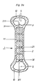
- FIG. 3a shows a blow molded body 1 with an elongated central part 11 and lump-like thickenings 12, 13 molded onto it. Hollow chambers 4, 5 are introduced into the lobe-like thickenings 12, 13.
- the reinforcing element 2 is provided with openings 21.
- a web-like bridge formation between the walls of the blow molded body has occurred in these openings by pressing the thermoplastic material out of the wall 3.
- Web-like bridge formations 31, 32 are also formed on the exposed edge regions of the reinforcing element.
- the web-like bridge 31 here has a tip-like elevation 311 deflected into the hollow chamber 4, while the web-like bridge 32 has a wavy surface 321.
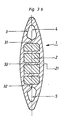
- FIG. 3b shows another cross section of the blow molded body 1, which can be referred to as a spindle shape.
- the reinforcing element 2 is embedded in the blow molded body 1 in accordance with the cross-sectional illustration in FIG. 1.
- the same features have been given the same reference symbols here as there.
- the surface designs of the bridge-like webs 31, 32 are also particularly striking here. In this case too, the wall thickness of the blow molding in the region of the hollow chambers 4, 5 is greater than above the reinforcing element 2.
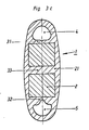
- 3c shows a further possible cross-sectional shape of the blow molded body 1 with an inserted reinforcing element 2, the features resulting in the same form as for the previously described cross sections.
- the same features have been given the same reference symbols.
- Fig. 4 shows possible variations of reinforcing elements, which lead from a simple board-like structure via a contour-shaped element and elements with openings and slits to ring-like or bow-like shapes up to curved wire structures.
- cross-sectional representations of the individual reinforcement elements are shown. These cross-sections include elongated, smooth shapes as well as rounded or angled shapes.
- the materials from which the reinforcing elements are formed can be selected according to the required purpose.
- FIG. 5 finally shows an embodiment of a blow molded body 1 produced according to the invention, in which the reinforcing element 2 is not completely enclosed by the thermoplastic material.
- This is a rounded blow molded body, in which the external pressure has only been used to flow around the end wall regions 22, 23 of the reinforcing element 2.
Landscapes
- Engineering & Computer Science (AREA)
- Mechanical Engineering (AREA)
- Chemical & Material Sciences (AREA)
- Composite Materials (AREA)
- Manufacturing & Machinery (AREA)
- Blow-Moulding Or Thermoforming Of Plastics Or The Like (AREA)
- Moulds For Moulding Plastics Or The Like (AREA)
Applications Claiming Priority (2)
| Application Number | Priority Date | Filing Date | Title |
|---|---|---|---|
| DE3730488 | 1987-09-11 | ||
| DE19873730488 DE3730488A1 (de) | 1987-09-11 | 1987-09-11 | Verfahren zur herstellung eines blasformkoerpers |
Publications (2)
| Publication Number | Publication Date |
|---|---|
| EP0306643A2 true EP0306643A2 (fr) | 1989-03-15 |
| EP0306643A3 EP0306643A3 (fr) | 1991-04-24 |
Family
ID=6335757
Family Applications (1)
| Application Number | Title | Priority Date | Filing Date |
|---|---|---|---|
| EP19880109984 Withdrawn EP0306643A3 (fr) | 1987-09-11 | 1988-06-23 | Procédé de fabrication d'un article moulé par soufflage |
Country Status (4)
| Country | Link |
|---|---|
| US (1) | US4911878A (fr) |
| EP (1) | EP0306643A3 (fr) |
| JP (1) | JPH01163041A (fr) |
| DE (1) | DE3730488A1 (fr) |
Cited By (4)
| Publication number | Priority date | Publication date | Assignee | Title |
|---|---|---|---|---|
| EP0413344A3 (en) * | 1989-08-17 | 1992-05-06 | Centro Sviluppo Settori Impiego S.R.L. | Process for preparing structural, heat-insulating shaped articles and articles obtainable thereby |
| US5219513A (en) * | 1989-08-17 | 1993-06-15 | Centro Sviluppo Settori Impiego S.R.L. | Process for preparing structural, heat-insulating shaped bodies, and bodies obtained thereby |
| EP0745471A1 (fr) * | 1995-06-02 | 1996-12-04 | Tsutsunaka Plastic Industry Co., Ltd. | Moulage par soufflage des feuilles et procédé de moulage |
| WO2007090453A3 (fr) * | 2006-02-10 | 2008-05-29 | Kautex Textron Gmbh & Co Kg | Procédé de fabrication d'un corps creux en plastique et d'un contenant en plastique |
Families Citing this family (11)
| Publication number | Priority date | Publication date | Assignee | Title |
|---|---|---|---|---|
| NL9001573A (nl) * | 1990-07-10 | 1992-02-03 | Wiva Bv | Werkwijze en inrichting voor het vervaardigen van een kunststof vat met versterkte kopwanden. |
| US5133591A (en) * | 1991-05-30 | 1992-07-28 | Semco Plastic Company, Inc. | Blow-molded plastic wheel and method for manufacturing same |
| US20020113342A1 (en) * | 1999-09-17 | 2002-08-22 | Tsai Shuang Chu | Method of making an elastic pad |
| DE10010900A1 (de) * | 2000-03-07 | 2001-09-13 | Ludwig Kreth | Kombiniertes Extrusions-Press-Verfahren zur Herstellung von Kunststoffteilen aller Art |
| EP1255028A3 (fr) * | 2001-05-03 | 2005-05-11 | Kautex Textron GmbH & Co. KG. | Support moulé pas soufflage |
| DE10150827A1 (de) * | 2001-10-15 | 2003-05-15 | Gummi Welz Gmbh & Co Kg | Verfahren zur Herstellung einer aufblasbaren vulkanisierten Dichtung |
| DE102007006472A1 (de) * | 2006-04-20 | 2007-11-08 | Continental Teves Ag & Co. Ohg | Scheibenbremse |
| US9023264B2 (en) | 2006-07-03 | 2015-05-05 | Kautex Textron Gmbh & Co. Kg | Method for producing a container of thermoplastic material |
| DE102011075829B4 (de) * | 2011-05-13 | 2013-07-11 | Metzeler Automotive Profiles Gmbh | Dichtung, insbesondere für ein Kraftfahrzeug, und Verfahren zur Herstellung einer solchen Dichtung |
| DE102014101752B4 (de) * | 2013-09-17 | 2023-09-21 | Cqlt Saargummi Technologies S.À.R.L. | Verfahren zur Bildung von Dichtungen an Dichtungsträgern |
| DE102015106960A1 (de) * | 2015-05-05 | 2016-11-10 | Bodo Richter | Verfahren und Vorrichtung zur Herstellung großvolumiger Behälter mit Flansch durch Kunststoff-Blasformen |
Family Cites Families (22)
| Publication number | Priority date | Publication date | Assignee | Title |
|---|---|---|---|---|
| GB977005A (en) * | 1962-09-14 | 1964-12-02 | Dunlop Rubber Australia Ltd | Improvements in cells for wet storage batteries |
| US3424623A (en) * | 1966-06-28 | 1969-01-28 | Michael J Oakley | Blow molded battery |
| JPS5026809B1 (fr) * | 1968-11-15 | 1975-09-03 | ||
| US3954369A (en) * | 1969-09-16 | 1976-05-04 | Elbatainer Kunststoff- Und Verpackungs-Gesellschaft Mbh & Co. | Apparatus for making a liquid container from thermoplastic synthetic material |
| US3919373A (en) * | 1969-09-16 | 1975-11-11 | Elbatainer Kunststoff | Method of making a liquid container from thermoplastic synthetic material |
| US3705931A (en) * | 1970-03-23 | 1972-12-12 | Air Lock Plastic Inc | Method for blow molding and compression molding thermoplastic material |
| JPS5330660A (en) * | 1976-09-02 | 1978-03-23 | Tousen Purasuto Kk | Ventilating pipe with synthetic resin silencer |
| US4213933A (en) * | 1978-03-15 | 1980-07-22 | Respiratory Care, Inc. | Method of making a blow molded container having an insert molded in situ |
| JPS5511823A (en) * | 1978-07-12 | 1980-01-28 | Showa Yuka Kk | Method of forming hollow formed article with insert |
| JPS5511846A (en) * | 1978-07-13 | 1980-01-28 | Showa Yuka Kk | Method of forming hollow formed article with insert |
| JPS5525380A (en) * | 1978-08-12 | 1980-02-23 | Kodama Kagaku Kogyo Kk | Method of molding hollow molded article inserted with predetermined parts internally |
| FI811938L (fi) * | 1981-06-22 | 1982-12-23 | Pyrkijae Oy | Foerfarande foer infaestande av en separat extra tank i en tank av plast i dess framstaellningsskede |
| JPS581529A (ja) * | 1981-06-26 | 1983-01-06 | Yoji Araki | 中空成形機において2室以上ある容器を一体成形する方法及び装置 |
| US4511529A (en) * | 1981-09-29 | 1985-04-16 | Baxter Travenol Laboratories, Inc. | Method of making a bottle closure |
| DE3234180C2 (de) * | 1982-09-15 | 1987-01-15 | K. Kurz Hessental GmbH & Co KG, 7170 Schwäbisch Hall | Verfahren zum Herstellen eines Kraftstoffbehälters mit mindestens einem Beruhigungstopf und Vorrichtung zur Durchführung des Verfahrens |
| JPS59120519A (ja) * | 1982-12-28 | 1984-07-12 | Yoji Araki | 自動車用ガソリンタンクの製造方法 |
| JPS6140116A (ja) * | 1984-04-11 | 1986-02-26 | Inoue Mtp Co Ltd | インサ−トを有する合成樹脂製中空体の成形方法 |
| JPS60236855A (ja) * | 1984-05-08 | 1985-11-25 | Kyowa Sangyo Kk | ヘツドレストの製造方法 |
| JPS615917A (ja) * | 1984-06-19 | 1986-01-11 | Nissan Shatai Co Ltd | ブロ−成形装置 |
| JPS6169554A (ja) * | 1984-09-12 | 1986-04-10 | マツダ株式会社 | 仕切部材を備えたプラスチック製タンクの製造方法 |
| JPS6176339A (ja) * | 1984-09-25 | 1986-04-18 | Nissan Shatai Co Ltd | 付属部品内蔵の樹脂成形体およびその成形装置 |
| US4891000A (en) * | 1987-02-06 | 1990-01-02 | Nissan Motor Co., Ltd. | Apparatus for blow moulding hollow article |
-
1987
- 1987-09-11 DE DE19873730488 patent/DE3730488A1/de active Granted
-
1988
- 1988-06-23 EP EP19880109984 patent/EP0306643A3/fr not_active Withdrawn
- 1988-09-09 US US07/242,317 patent/US4911878A/en not_active Expired - Fee Related
- 1988-09-09 JP JP63224851A patent/JPH01163041A/ja active Pending
Cited By (5)
| Publication number | Priority date | Publication date | Assignee | Title |
|---|---|---|---|---|
| EP0413344A3 (en) * | 1989-08-17 | 1992-05-06 | Centro Sviluppo Settori Impiego S.R.L. | Process for preparing structural, heat-insulating shaped articles and articles obtainable thereby |
| US5219513A (en) * | 1989-08-17 | 1993-06-15 | Centro Sviluppo Settori Impiego S.R.L. | Process for preparing structural, heat-insulating shaped bodies, and bodies obtained thereby |
| EP0745471A1 (fr) * | 1995-06-02 | 1996-12-04 | Tsutsunaka Plastic Industry Co., Ltd. | Moulage par soufflage des feuilles et procédé de moulage |
| WO2007090453A3 (fr) * | 2006-02-10 | 2008-05-29 | Kautex Textron Gmbh & Co Kg | Procédé de fabrication d'un corps creux en plastique et d'un contenant en plastique |
| EP2147772A1 (fr) * | 2006-02-10 | 2010-01-27 | Kautex Textron GmbH & Co. KG. | Corps creux en plastique |
Also Published As
| Publication number | Publication date |
|---|---|
| EP0306643A3 (fr) | 1991-04-24 |
| JPH01163041A (ja) | 1989-06-27 |
| DE3730488C2 (fr) | 1990-02-01 |
| US4911878A (en) | 1990-03-27 |
| DE3730488A1 (de) | 1989-03-23 |
Similar Documents
| Publication | Publication Date | Title |
|---|---|---|
| DE69826733T2 (de) | Faserverstärkter Formkörper aus Kunststoff und Verfahren zur dessen Herstellung | |
| DE2800482C2 (de) | Verwendung von viskosen Flüssigkeiten als fluides Medium bei einem Verfahren zur Herstellung von Formkörpern | |
| DE69219157T2 (de) | Spritzgiessen von kunststoffgegenständen die hohlförmige rippen aufweisen | |
| EP0306643A2 (fr) | Procédé de fabrication d'un article moulé par soufflage | |
| DE2817572C2 (de) | Verfahren zum Herstellen eines Behälters aus Polyäthylenterephthalat | |
| EP0393315B1 (fr) | Procédé pour mouler par injection des pièces en matière plastique remplies de liquide et appareil pour la réalisation du procédé | |
| EP0440020A2 (fr) | Procédé pour fabriquer des corps creux moulés par injection en matière plastique et dispositif pour la mise en oeuvre du procédé | |
| DE102007048211B4 (de) | Verfahren und Vorrichtung zur Herstellung einer Küvette sowie damit hergestellte Küvette | |
| CH628567A5 (de) | Vorrichtung zur herstellung eines kunststoff-hohlkoerpers. | |
| DE2359282C3 (de) | Vorrichtung zur Herstellung von Profilen aus geschäumten Thermoplasten | |
| DE4226390C2 (de) | Hohlkörper-Spritzgießverfahren | |
| DE3205000A1 (de) | Extruderkopf zum extrudieren von formlingen fuer rolladenstaebe, selbsttragende zierleisten u.dgl. sowie damit herzustellender formling | |
| DE3438448C2 (fr) | ||
| DE10009559A1 (de) | Verfahren zur Herstellung von expansionsgeformten Gegenständen aus faserverstärktem thermoplastischen Harz | |
| DE69808219T2 (de) | Verfahren zur herstellung von plastikformlingen und im verfahren benutzter kern | |
| DE2342789C2 (de) | Vorrichtung zur diskontinuierlichen Herstellung von Mehrschicht-Formkörpern | |
| DE60101777T2 (de) | Verfahren zur Herstellung einer beschichteten Türhaltestange für Fahrzeuge | |
| CH662303A5 (de) | Kombinationsteil aus einem kunststoffrahmen und einer perforierten metallfolie. | |
| DE69407074T2 (de) | Verfahren zur Herstellung eines länglichen Gegenstandes und Spritzgiessvorrichtung zu dessen Herstellung | |
| DE3439101A1 (de) | Verbundkoerper-herstellungsverfahren | |
| DE19936956B4 (de) | Verfahren zum Herstellen eines Kunststofformteils | |
| DE4216393C2 (de) | Nachmischer für Formwerkzeuge der RIM-Technik | |
| DE4204627A1 (de) | Lagerachse fuer fahrzeugsonnenblenden und verfahren zum herstellen einer solchen | |
| DE2558952C3 (de) | Verfahren zum Herstellen von Befestigungselementen und Vorrichtung zur Durchführung des Verfahrens | |
| EP0878689B1 (fr) | Fabrications par injection d'un mètre pliant et renforcement longitudinal |
Legal Events
| Date | Code | Title | Description |
|---|---|---|---|
| PUAI | Public reference made under article 153(3) epc to a published international application that has entered the european phase |
Free format text: ORIGINAL CODE: 0009012 |
|
| AK | Designated contracting states |
Kind code of ref document: A2 Designated state(s): ES FR GB IT NL |
|
| 17P | Request for examination filed |
Effective date: 19901217 |
|
| PUAL | Search report despatched |
Free format text: ORIGINAL CODE: 0009013 |
|
| AK | Designated contracting states |
Kind code of ref document: A3 Designated state(s): ES FR GB IT NL |
|
| 17Q | First examination report despatched |
Effective date: 19920424 |
|
| STAA | Information on the status of an ep patent application or granted ep patent |
Free format text: STATUS: THE APPLICATION IS DEEMED TO BE WITHDRAWN |
|
| 18D | Application deemed to be withdrawn |
Effective date: 19930414 |