EP0306743A2 - Procédé de filtrage de suie et filtre de suie pour un moteur diesel - Google Patents
Procédé de filtrage de suie et filtre de suie pour un moteur diesel Download PDFInfo
- Publication number
- EP0306743A2 EP0306743A2 EP88113462A EP88113462A EP0306743A2 EP 0306743 A2 EP0306743 A2 EP 0306743A2 EP 88113462 A EP88113462 A EP 88113462A EP 88113462 A EP88113462 A EP 88113462A EP 0306743 A2 EP0306743 A2 EP 0306743A2
- Authority
- EP
- European Patent Office
- Prior art keywords
- soot filter
- filter device
- combustion chamber
- burner
- fuel
- Prior art date
- Legal status (The legal status is an assumption and is not a legal conclusion. Google has not performed a legal analysis and makes no representation as to the accuracy of the status listed.)
- Granted
Links
Images

Classifications
-
- F—MECHANICAL ENGINEERING; LIGHTING; HEATING; WEAPONS; BLASTING
- F01—MACHINES OR ENGINES IN GENERAL; ENGINE PLANTS IN GENERAL; STEAM ENGINES
- F01N—GAS-FLOW SILENCERS OR EXHAUST APPARATUS FOR MACHINES OR ENGINES IN GENERAL; GAS-FLOW SILENCERS OR EXHAUST APPARATUS FOR INTERNAL-COMBUSTION ENGINES
- F01N3/00—Exhaust or silencing apparatus having means for purifying, rendering innocuous, or otherwise treating exhaust
- F01N3/02—Exhaust or silencing apparatus having means for purifying, rendering innocuous, or otherwise treating exhaust for cooling, or for removing solid constituents of, exhaust
- F01N3/021—Exhaust or silencing apparatus having means for purifying, rendering innocuous, or otherwise treating exhaust for cooling, or for removing solid constituents of, exhaust by means of filters
- F01N3/023—Exhaust or silencing apparatus having means for purifying, rendering innocuous, or otherwise treating exhaust for cooling, or for removing solid constituents of, exhaust by means of filters using means for regenerating the filters, e.g. by burning trapped particles
- F01N3/025—Exhaust or silencing apparatus having means for purifying, rendering innocuous, or otherwise treating exhaust for cooling, or for removing solid constituents of, exhaust by means of filters using means for regenerating the filters, e.g. by burning trapped particles using fuel burner or by adding fuel to exhaust
-
- F—MECHANICAL ENGINEERING; LIGHTING; HEATING; WEAPONS; BLASTING
- F01—MACHINES OR ENGINES IN GENERAL; ENGINE PLANTS IN GENERAL; STEAM ENGINES
- F01N—GAS-FLOW SILENCERS OR EXHAUST APPARATUS FOR MACHINES OR ENGINES IN GENERAL; GAS-FLOW SILENCERS OR EXHAUST APPARATUS FOR INTERNAL-COMBUSTION ENGINES
- F01N2240/00—Combination or association of two or more different exhaust treating devices, or of at least one such device with an auxiliary device, not covered by indexing codes F01N2230/00 or F01N2250/00, one of the devices being
- F01N2240/14—Combination or association of two or more different exhaust treating devices, or of at least one such device with an auxiliary device, not covered by indexing codes F01N2230/00 or F01N2250/00, one of the devices being a fuel burner
-
- F—MECHANICAL ENGINEERING; LIGHTING; HEATING; WEAPONS; BLASTING
- F02—COMBUSTION ENGINES; HOT-GAS OR COMBUSTION-PRODUCT ENGINE PLANTS
- F02B—INTERNAL-COMBUSTION PISTON ENGINES; COMBUSTION ENGINES IN GENERAL
- F02B3/00—Engines characterised by air compression and subsequent fuel addition
- F02B3/06—Engines characterised by air compression and subsequent fuel addition with compression ignition
Definitions
- the invention relates to a soot filter device for a diesel engine according to the preamble of patent claim 1.
- diesel engines produce soot, which should be filtered out of the exhaust gases.
- Ceramic soot filters are being tested, which can absorb the soot from 5 to 8 hours of driving.
- the filter must then be regenerated.
- the regeneration is carried out by burning the soot particles with high exhaust gas temperatures of at least 600 ° C.
- Such high exhaust gas temperatures are not available in diesel engines due to the high excess air.
- Methods are currently being tested in which the filter device has its own burner. Because this burner does not counter the pulsating exhaust gas pressure of the diesel engine facilities are being tested, in which the filter is bridged by an additional silencer during regeneration.
- the invention has for its object to provide a soot filter device of the type specified in the preamble of claim 1, in which the regeneration of the filter can be carried out during operation of the diesel engine without redirecting the engine exhaust.
- soot filter device only a partial combustion of the fuel supplied takes place in the main combustion chamber of the burner with the aid of air that is forcibly fed in a certain volume flow, but without soot formation.
- the unburned part of the fuel is fed together with the fuel gases to the afterburning chamber, where it burns due to the oxygen contained in the engine exhaust.
- the first part of the combustion is carried out with external air supplied, and the engine exhaust gases are used only for post-combustion. Since compressed air is only supplied in substoichiometric amounts for the main combustion, the air requirement is relatively low.
- the atomizer nozzle of the burner is preferably an annular nozzle provided with swirl elements.
- This ring nozzle has an annular atomizing tongue, along which fuel passes along the inside, which is generated by the rotating air flow to form a flow cone is atomized. Reliable, stable combustion is achieved despite the pulsating back pressure and despite the lack of air by using such an "air atomizing nozzle". If all the air for the main combustion is supplied with a differential pressure of at least 10 mbar, an intensive mixture of fine fuel mist with the combustion air is obtained directly behind the nozzle. Together with the hot gas recirculation caused by the swirl elements of the atomizer nozzle, this leads to a combustion that is independent of the pressure pulsations.
- the compressed air supplied to the burner can be taken from the compressed air system of the vehicle and fed to the atomizer nozzle via a nozzle operated with a supercritical pressure ratio.
- Supercritical pressure ratio means that the air flows in the narrowest nozzle cross-section at least at the speed of sound. A burner output that is independent of the pressure pulsations of the engine exhaust gas can thus be operated.
- the combustion air can be conveyed by a displacement fan.
- the air mass flow is not or only slightly influenced by the back pressure of the diesel exhaust gas flow, and burner operation is ensured with an air flow rate unaffected by the pulsating engine pressure and thus unaffected burner output. If you couple the air compressor with the speed of the diesel engine and also deliver the fuel with a positive displacement pump, you get a speed-proportional mixture quantity control. If the speed of the diesel engine changes, the burner output adapts accordingly changed exhaust gas mass flow. This allows the temperature at the filter to be optimally maintained during regeneration.
- the burner is so small that it can easily be installed in the filter housing and cooled with the engine exhaust gas by means of a heat exchanger.
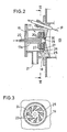
- the filter device shown in FIG. 1 has a cylindrical housing 10.
- the housing 10 has a radial or tangential inlet 11 for the engine exhaust gases at one end and contains a ceramic filter 12 which takes up the entire housing cross section.
- a ceramic filter 12 which takes up the entire housing cross section.
- the outlet connection 13 At the other end of the housing 10 there is the outlet connection 13, through which the engine exhaust gases and combustion gases emerge from the housing.
- the exhaust gas inlet 11 leads into an annular distributor chamber 14 which surrounds the main combustion chamber 15 of the burner 16.
- the atomizing nozzle 17 is attached to the cover wall 18 of the nozzle housing 19. This cover wall 18 is flanged to the end wall of the housing 10 and delimits the main combustion chamber 15.
- the fuel line 20 leads into the nozzle housing 19 and is connected directly to the atomizer nozzle 17.
- the nozzle housing 19 also has an air inlet 21 through which compressed air is pressed into the interior of the nozzle housing. As shown in FIG. 2, the fuel line 20 leads through the interior of the nozzle body 17a and emerges from its end face.
- numerous air-conducting swirl elements 23 in the form of wings are arranged on the flange-like end wall 22 of the nozzle body.
- swirl elements 23 are inclined in the circumferential direction according to FIG. 3 and they taper towards the inner end.
- the swirl elements 23 delimit channels 24 through which the radially inflowing air contains a peripheral component.
- Each of the channels 24 decreases in cross section towards its inner end, so that the air in each channel 24 is increasingly accelerated.
- the swirl elements 23 are arranged between the end wall 22 and a plate 25 running parallel to this end wall.
- the end wall of the plate 25 facing away from the swirl elements 23 forms the boundary wall of a further nozzle space, which is also equipped with swirl elements 26 which are attached to the end face of a further plate 27.
- the plate 27 runs parallel to the plate 25 and its swirl elements 26 are designed and arranged in the same way as the swirl elements 23 of the plate 22.
- the air flowing laterally into the nozzle housing 19 through the compressed air inlet 21 is distributed in the interior of the nozzle housing and flows radially into the channels 24 between the swirl elements 23 and into the corresponding channels between the swirl elements 26.
- the swirl elements give the air a swirl, i.e. a circular motion.
- the plate 25 has an annular shape and its inner edge has the shape of an annular cutting edge 29 which projects axially in the flow direction and tapers towards the end.
- the inner edge of the annular plate 27 is also bent axially in the flow direction and forms a conical ring 30 , which surrounds the cutting edge 29 at a radial distance.
- the liquid fuel emerging from the tube 20a is caught by the rotating air stream and sprayed onto the inside of the cutting edge 29.
- the cutting edge 29 is surrounded on both sides by rotating and axially moving air streams which tear off the fuel from the circular sharp tip of the cutting edge 29 and distribute it finely and evenly in droplet form.
- the fuel droplets mix with the combustion air and together with it enter the tubular main combustion chamber 15.
- ring-shaped flow rollers in which a part of the mixture flow is returned, arise in the main combustion chamber 15 and rotate around the longitudinal axis.
- An electrode 31 is arranged in the main combustion chamber 15 to ignite the mixture.
- the main combustion chamber 15 is delimited at the end facing away from the atomizer nozzle 17 by an annular wall 32 which forms an opening 33 for the exit of the fuel gases. At a distance behind the annular wall 32 there is an end wall 34 which delimits the space 35 located behind the main combustion chamber 15.
- Heat exchanger fins 36 extend on the peripheral wall of the outside of the main combustion chamber 15 and extend to the end wall 34. Between these heat exchanger fins 36, the fuel gases flow radially out of the space 35 into the afterburning chamber 37, which is delimited at one end by the filter 12.
- An annular passage 38 leads from the distribution chamber 14 to the heat exchanger fins 36.
- the engine exhaust gases flow through the passage 38, along the heat exchanger fins 36, and are then mixed with the combustion gases to flow together into the afterburning chamber 37. From there, the hot gas mixture flows through the filter 12 to the outlet port 13.
- the chamber 35 forms a cross-flow mixer 39 on its circumference, in which an intensive mixing of the gas flows takes place.
- the compressed air inlet 21 contains a critically flowed nozzle 40, which is connected via a switching valve 41 to the compressed air collector 42 of the diesel engine DM.
- the output shaft of the diesel engine drives (directly or via a reduction) a blower 43 which feeds the compressed air collector 42.
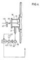
- FIG. 4 shows an exemplary embodiment in which the compressed air supplied to the atomizing nozzle 17 is generated by a volumetric pump or displacement pump 45.
- the positive displacement pump 45 is coupled via a clutch 46 to the output shaft 47 of the diesel engine DM (directly or via a gearbox).
- the fuel is also fed to the fuel line 20 via a positive displacement pump 48 which is driven by the output shaft 47 of the diesel engine. Since the quantities of compressed air and fuel both vary depending on the engine speed, but their mutual ratio remains constant, the mixture quantity is controlled in proportion to the speed. As a result, the burner output always adapts to the changed exhaust gas flow when the speed of the diesel engine varies. This means that the temperature at the filter can be kept largely constant during regeneration.
Landscapes
- Engineering & Computer Science (AREA)
- Chemical & Material Sciences (AREA)
- Combustion & Propulsion (AREA)
- Mechanical Engineering (AREA)
- General Engineering & Computer Science (AREA)
- Processes For Solid Components From Exhaust (AREA)
- Exhaust Gas After Treatment (AREA)
- Extrusion Moulding Of Plastics Or The Like (AREA)
- External Artificial Organs (AREA)
- Filtering Of Dispersed Particles In Gases (AREA)
Priority Applications (1)
| Application Number | Priority Date | Filing Date | Title |
|---|---|---|---|
| AT88113462T ATE81887T1 (de) | 1987-09-05 | 1988-08-19 | Russfilterverfahren und russfiltervorrichtung fuer einen dieselmotor. |
Applications Claiming Priority (2)
| Application Number | Priority Date | Filing Date | Title |
|---|---|---|---|
| DE3729861A DE3729861C2 (de) | 1987-09-05 | 1987-09-05 | Verfahren zum Betreiben einer Rußfiltervorrichtung für einen Dieselmotor und Rußfiltervorrichtung zur Durchführung dieses Verfahrens |
| DE3729861 | 1987-09-05 |
Publications (3)
| Publication Number | Publication Date |
|---|---|
| EP0306743A2 true EP0306743A2 (fr) | 1989-03-15 |
| EP0306743A3 EP0306743A3 (en) | 1990-01-31 |
| EP0306743B1 EP0306743B1 (fr) | 1992-10-28 |
Family
ID=6335373
Family Applications (1)
| Application Number | Title | Priority Date | Filing Date |
|---|---|---|---|
| EP88113462A Expired - Lifetime EP0306743B1 (fr) | 1987-09-05 | 1988-08-19 | Procédé de filtrage de suie et filtre de suie pour un moteur diesel |
Country Status (8)
| Country | Link |
|---|---|
| US (1) | US4951464A (fr) |
| EP (1) | EP0306743B1 (fr) |
| JP (1) | JP2559620B2 (fr) |
| AT (1) | ATE81887T1 (fr) |
| CA (1) | CA1336966C (fr) |
| DE (2) | DE3729861C2 (fr) |
| FI (1) | FI102629B (fr) |
| GR (1) | GR3006690T3 (fr) |
Cited By (17)
| Publication number | Priority date | Publication date | Assignee | Title |
|---|---|---|---|---|
| EP0367280A1 (fr) * | 1988-11-04 | 1990-05-09 | Klöckner-Humboldt-Deutz Aktiengesellschaft | Système de filtre de particules |
| EP0438682A3 (en) * | 1990-01-25 | 1992-02-26 | Man Technologie Aktiengesellschaft | Exhaust system with particle filter and regeneration burner |
| EP0331795B1 (fr) * | 1988-03-09 | 1992-03-18 | Webasto AG Fahrzeugtechnik | Brûleur fonctionnant avec les gaz d'échappement d'un moteur à combustion interne |
| EP0532044A1 (fr) * | 1991-09-12 | 1993-03-17 | Firma J. Eberspächer | Brûleur pour un filtre à particules de gaz d'échappement d'un moteur diesel |
| EP0532031A1 (fr) * | 1991-09-12 | 1993-03-17 | Firma J. Eberspächer | Dispositif pour la régénération thermique de filtres à particules pour les gaz d'échappement de moteurs diesel |
| TR25558A (tr) * | 1990-08-07 | 1993-07-01 | Man Technologie Gmbh | BIR PARTIKüL FILTRESI ILE BIR REJENERASYON BRüLÖRüNE SAHIP ATIK GAZ BORUSU |
| EP0554499A1 (fr) * | 1992-02-01 | 1993-08-11 | ERNST-APPARATEBAU GmbH & Co. | Filtre de la suie avec une chambre annulaire |
| US5320523A (en) * | 1992-08-28 | 1994-06-14 | General Motors Corporation | Burner for heating gas stream |
| EP0583507B1 (fr) * | 1992-08-14 | 1996-03-27 | ERNST APPARATEBAU GmbH & Co. | Filtre à suie avec générateur de gaz chaud |
| EP1752633A1 (fr) * | 2005-08-11 | 2007-02-14 | Deutsches Zentrum für Luft- und Raumfahrt e.V. | Appareil pour la génération de gaz dans un système d'échappement d'un moteur thermique |
| EP1939419A1 (fr) | 2006-12-19 | 2008-07-02 | J. Eberspächer GmbH & Co. KG | Système d'échappement pour moteurs à combustion interne |
| WO2023241907A1 (fr) * | 2022-06-13 | 2023-12-21 | Mercedes-Benz Group AG | Brûleur pour véhicule automobile et véhicule automobile comprenant au moins un tel brûleur |
| WO2023242030A1 (fr) * | 2022-06-13 | 2023-12-21 | Mercedes-Benz Group AG | Brûleur pour véhicule automobile, procédé de fonctionnement d'un tel brûleur et véhicule automobile |
| WO2023242031A1 (fr) * | 2022-06-13 | 2023-12-21 | Mercedes-Benz Group AG | Brûleur pour véhicule automobile et véhicule automobile comportant au moins un tel brûleur |
| WO2023242029A1 (fr) * | 2022-06-13 | 2023-12-21 | Mercedes-Benz Group AG | Brûleur pour véhicule automobile et véhicule automobile comprenant au moins un tel brûleur |
| WO2024104671A1 (fr) * | 2022-11-14 | 2024-05-23 | Robert Bosch Gmbh | Unité de brûleur dans un conduit d'échappement d'un moteur à combustion interne |
| DE102023209182A1 (de) * | 2023-09-20 | 2025-03-20 | Friedrich Boysen Gmbh & Co. Kg | Abgasbrenner und Abgasnachbehandlungssystem |
Families Citing this family (50)
| Publication number | Priority date | Publication date | Assignee | Title |
|---|---|---|---|---|
| DE4015013B4 (de) * | 1990-05-10 | 2004-09-16 | Deutz Ag | Mischvorrichtung |
| DE4038064A1 (de) * | 1990-11-29 | 1992-06-04 | Kloeckner Humboldt Deutz Ag | Brenner |
| US5339630A (en) * | 1992-08-28 | 1994-08-23 | General Motors Corporation | Exhaust burner catalyst preheater |
| DE4242090A1 (de) * | 1992-12-14 | 1994-06-16 | Kloeckner Humboldt Deutz Ag | Partikelfiltersystem |
| DE4242093C2 (de) * | 1992-12-14 | 2003-05-22 | Deutz Ag | Funktionsüberwachung eines Partikelfiltersystems |
| DE4242094B4 (de) * | 1992-12-14 | 2004-09-02 | Deutz Ag | Regenerationsbrenner mit einstückiger Ausbildung von dessen Ventilgehäuse und Brennkammer |
| DE4242091C2 (de) * | 1992-12-14 | 2002-11-07 | Deutz Ag | Vorrichtung zum Starten des Regenerationsbrenners eines Partikelfiltersystems bei niedrigen Temperaturen |
| DE4242096B4 (de) * | 1992-12-14 | 2004-03-25 | Deutz Ag | Spülluftversorgung eines Partikelfiltersystems |
| DE4242095C2 (de) * | 1992-12-14 | 1996-10-31 | Kloeckner Humboldt Deutz Ag | Verfahren zur Verringerung der Schadstoffemissionen von Dieselmotoren und ein Partikelfiltersystem zu seiner Durchführung |
| DE4303720C2 (de) * | 1993-02-09 | 2003-12-24 | Deutz Ag | Partikelfiltersystem |
| DE4307525A1 (de) * | 1993-03-10 | 1994-09-15 | Audi Ag | Verfahren und Vorrichtung zur Nachbehandlung der Abgase einer Brennkraftmaschine |
| DE4440716C2 (de) * | 1994-11-15 | 1997-02-27 | Daimler Benz Ag | Rußfilteranlage für Verbrennungsmotor |
| DE19729246C2 (de) * | 1997-07-09 | 2001-06-28 | Deutsch Zentr Luft & Raumfahrt | Zerstäuberdüse für die Kraftstoffzerstäubung in Brennern |
| SE525197C2 (sv) * | 2003-06-18 | 2004-12-21 | Volvo Lastvagnar Ab | Anordning för reglering av temperaturen hos avgaser från ett avgassystem försett med aktivt regenererbart filter |
| US20060218902A1 (en) * | 2005-03-31 | 2006-10-05 | Solar Turbines Incorporated | Burner assembly for particulate trap regeneration |
| US7481048B2 (en) * | 2005-06-30 | 2009-01-27 | Caterpillar Inc. | Regeneration assembly |
| US7406822B2 (en) * | 2005-06-30 | 2008-08-05 | Caterpillar Inc. | Particulate trap regeneration system and control strategy |
| US20070158466A1 (en) * | 2005-12-29 | 2007-07-12 | Harmon Michael P | Nozzle assembly |
| US20070235556A1 (en) * | 2006-03-31 | 2007-10-11 | Harmon Michael P | Nozzle assembly |
| US20070228191A1 (en) * | 2006-03-31 | 2007-10-04 | Caterpillar Inc. | Cooled nozzle assembly for urea/water injection |
| DE102006015841B3 (de) * | 2006-04-03 | 2007-08-02 | TWK Engineering Entwicklungstechnik (GbR) (vertretungsberechtigte Gesellschafter Herrn Thomas Winter, Jagdhaus am Breitenberg, 56244 Ötzingen und Herrn Waldemar Karsten, Am Merzenborn 6, 56422 Wirges) | Verfahren zur Erzeugung von Heißgas |
| US7874148B2 (en) * | 2007-03-15 | 2011-01-25 | Deere & Company | Regeneration system and method for particulate traps |
| US20080264046A1 (en) * | 2007-04-30 | 2008-10-30 | Caterpillar Inc. | Regeneration device having air-assisted fuel nozzle |
| US8459017B2 (en) * | 2008-04-09 | 2013-06-11 | Woodward, Inc. | Low pressure drop mixer for radial mixing of internal combustion engine exhaust flows, combustor incorporating same, and methods of mixing |
| JP5246005B2 (ja) * | 2009-04-15 | 2013-07-24 | 株式会社Ihi | バーナ装置 |
| US20110289906A1 (en) * | 2009-04-27 | 2011-12-01 | Nicholas Morley | Miniature Regeneration Unit |
| JP4720935B2 (ja) | 2009-07-14 | 2011-07-13 | 株式会社Ihi | バーナ装置 |
| JP5353822B2 (ja) * | 2009-09-30 | 2013-11-27 | 株式会社Ihi | 着火装置 |
| US9506385B2 (en) | 2010-07-15 | 2016-11-29 | Faurecia Emissions Control Technologies, Usa, Llc | Fuel fired burner for vehicle exhaust component |
| US8938954B2 (en) | 2012-04-19 | 2015-01-27 | Donaldson Company, Inc. | Integrated exhaust treatment device having compact configuration |
| US8959902B2 (en) * | 2013-02-27 | 2015-02-24 | Tenneco Automotive Operating Company Inc. | Exhaust treatment burner and mixer system |
| US8991163B2 (en) | 2013-02-27 | 2015-03-31 | Tenneco Automotive Operating Company Inc. | Burner with air-assisted fuel nozzle and vaporizing ignition system |
| US9027331B2 (en) | 2013-02-27 | 2015-05-12 | Tenneco Automotive Operating Company Inc. | Exhaust aftertreatment burner with preheated combustion air |
| US9027332B2 (en) | 2013-02-27 | 2015-05-12 | Tenneco Automotive Operating Company Inc. | Ion sensor with decoking heater |
| US9364790B2 (en) | 2013-05-07 | 2016-06-14 | Tenneco Automotive Operating Company Inc. | Exhaust mixing assembly |
| US9314750B2 (en) | 2013-05-07 | 2016-04-19 | Tenneco Automotive Operating Company Inc. | Axial flow atomization module |
| US9334781B2 (en) | 2013-05-07 | 2016-05-10 | Tenneco Automotive Operating Company Inc. | Vertical ultrasonic decomposition pipe |
| US9291081B2 (en) | 2013-05-07 | 2016-03-22 | Tenneco Automotive Operating Company Inc. | Axial flow atomization module |
| US9352276B2 (en) | 2013-05-07 | 2016-05-31 | Tenneco Automotive Operating Company Inc. | Exhaust mixing device |
| US9289724B2 (en) | 2013-05-07 | 2016-03-22 | Tenneco Automotive Operating Company Inc. | Flow reversing exhaust gas mixer |
| US9534525B2 (en) | 2015-05-27 | 2017-01-03 | Tenneco Automotive Operating Company Inc. | Mixer assembly for exhaust aftertreatment system |
| DE102021001581B4 (de) | 2021-03-25 | 2024-03-07 | Mercedes-Benz Group AG | Brenner für ein Kraftfahrzeug sowie Kraftfahrzeug |
| DE102021001584B4 (de) | 2021-03-25 | 2024-03-07 | Mercedes-Benz Group AG | Brenner für ein Kraftfahrzeug |
| DE102021001580A1 (de) | 2021-03-25 | 2022-09-29 | Mercedes-Benz Group AG | Brenner für ein Kraftfahrzeug sowie Kraftfahrzeug mit wenigstens einem solchen Brenner |
| DE102021001585B4 (de) | 2021-03-25 | 2024-08-22 | DVGW Deutscher Verein des Gas- und Wasserfaches e.V. - Technisch-wissenschaftlicher Verein | Brenner für einen Abgastrakt eines Kraftfahrzeugs sowie Kraftfahrzeug |
| DE102022002118B3 (de) | 2022-06-13 | 2023-09-21 | Mercedes-Benz Group AG | Brenner für ein Kraftfahrzeug sowie Kraftfahrzeug mit wenigstens einem solchen Brenner |
| DE102022002112A1 (de) | 2022-06-13 | 2023-12-14 | Mercedes-Benz Group AG | Brenner für ein Kraftfahrzeug sowie Kraftfahrzeug mit wenigstens einem solchen Brenner |
| DE102022002114B4 (de) | 2022-06-13 | 2024-01-11 | Mercedes-Benz Group AG | Brenner für ein Kraftfahrzeug sowie Kraftfahrzeug mit wenigstens einem solchen Brenner |
| DE102023000324A1 (de) | 2023-02-03 | 2024-08-08 | Mercedes-Benz Group AG | Brenner für eine Abgasanlage einer Verbrennungskraftmaschine, insbesondere eines Kraftfahrzeugs, Verfahren zum Betreiben eines solchen Brenners sowie Verbrennungskraftmaschine für ein Kraftfahrzeug |
| DE102023003068B3 (de) | 2023-07-26 | 2024-12-12 | Mercedes-Benz Group AG | Brenner für ein Kraftfahrzeug sowie Kraftfahrzeug mit wenigstens einem solchen Brenner |
Family Cites Families (9)
| Publication number | Priority date | Publication date | Assignee | Title |
|---|---|---|---|---|
| US3703259A (en) * | 1971-05-03 | 1972-11-21 | Gen Electric | Air blast fuel atomizer |
| DE3219948A1 (de) * | 1982-05-27 | 1983-12-01 | Bayerische Motoren Werke AG, 8000 München | Brenner fuer einen russfilter von brennkraftmaschinen |
| JPS5939915A (ja) * | 1982-08-27 | 1984-03-05 | Mazda Motor Corp | ディ−ゼルエンジンの排気ガス浄化装置 |
| JPS5943621U (ja) * | 1982-09-13 | 1984-03-22 | マツダ株式会社 | デイ−ゼルエンジンの排気ガス浄化装置 |
| JPS5988209U (ja) * | 1982-12-04 | 1984-06-14 | マツダ株式会社 | デイ−ゼルエンジンの排気ガス浄化装置 |
| JPS59100917U (ja) * | 1982-12-24 | 1984-07-07 | 日産自動車株式会社 | 内燃機関の排気微粒子処理装置 |
| JPS59153914A (ja) * | 1983-02-21 | 1984-09-01 | Nissan Motor Co Ltd | 内燃機関における排気微粒子捕集用トラツプの再生用バ−ナ−の制御装置 |
| JPH0627500B2 (ja) * | 1983-07-29 | 1994-04-13 | 三菱自動車工業株式会社 | ディ−ゼル微粒子フィルタ−再生装置 |
| US4651524A (en) * | 1984-12-24 | 1987-03-24 | Arvin Industries, Inc. | Exhaust processor |
-
1987
- 1987-09-05 DE DE3729861A patent/DE3729861C2/de not_active Expired - Lifetime
-
1988
- 1988-08-19 DE DE8888113462T patent/DE3875568D1/de not_active Expired - Lifetime
- 1988-08-19 AT AT88113462T patent/ATE81887T1/de not_active IP Right Cessation
- 1988-08-19 EP EP88113462A patent/EP0306743B1/fr not_active Expired - Lifetime
- 1988-09-01 FI FI884045A patent/FI102629B/fi not_active IP Right Cessation
- 1988-09-02 US US07/240,270 patent/US4951464A/en not_active Expired - Lifetime
- 1988-09-02 CA CA000576502A patent/CA1336966C/fr not_active Expired - Fee Related
- 1988-09-05 JP JP22218488A patent/JP2559620B2/ja not_active Expired - Fee Related
-
1992
- 1992-12-28 GR GR920403154T patent/GR3006690T3/el unknown
Cited By (19)
| Publication number | Priority date | Publication date | Assignee | Title |
|---|---|---|---|---|
| EP0331795B1 (fr) * | 1988-03-09 | 1992-03-18 | Webasto AG Fahrzeugtechnik | Brûleur fonctionnant avec les gaz d'échappement d'un moteur à combustion interne |
| EP0367280A1 (fr) * | 1988-11-04 | 1990-05-09 | Klöckner-Humboldt-Deutz Aktiengesellschaft | Système de filtre de particules |
| EP0438682A3 (en) * | 1990-01-25 | 1992-02-26 | Man Technologie Aktiengesellschaft | Exhaust system with particle filter and regeneration burner |
| TR25558A (tr) * | 1990-08-07 | 1993-07-01 | Man Technologie Gmbh | BIR PARTIKüL FILTRESI ILE BIR REJENERASYON BRüLÖRüNE SAHIP ATIK GAZ BORUSU |
| EP0532044A1 (fr) * | 1991-09-12 | 1993-03-17 | Firma J. Eberspächer | Brûleur pour un filtre à particules de gaz d'échappement d'un moteur diesel |
| EP0532031A1 (fr) * | 1991-09-12 | 1993-03-17 | Firma J. Eberspächer | Dispositif pour la régénération thermique de filtres à particules pour les gaz d'échappement de moteurs diesel |
| EP0554499A1 (fr) * | 1992-02-01 | 1993-08-11 | ERNST-APPARATEBAU GmbH & Co. | Filtre de la suie avec une chambre annulaire |
| EP0583507B1 (fr) * | 1992-08-14 | 1996-03-27 | ERNST APPARATEBAU GmbH & Co. | Filtre à suie avec générateur de gaz chaud |
| US5320523A (en) * | 1992-08-28 | 1994-06-14 | General Motors Corporation | Burner for heating gas stream |
| EP1752633A1 (fr) * | 2005-08-11 | 2007-02-14 | Deutsches Zentrum für Luft- und Raumfahrt e.V. | Appareil pour la génération de gaz dans un système d'échappement d'un moteur thermique |
| EP1939419A1 (fr) | 2006-12-19 | 2008-07-02 | J. Eberspächer GmbH & Co. KG | Système d'échappement pour moteurs à combustion interne |
| US8006487B2 (en) | 2006-12-19 | 2011-08-30 | J. Eberspaecher Gmbh & Co. Kg | Exhaust system for an internal combustion engine |
| WO2023241907A1 (fr) * | 2022-06-13 | 2023-12-21 | Mercedes-Benz Group AG | Brûleur pour véhicule automobile et véhicule automobile comprenant au moins un tel brûleur |
| WO2023242030A1 (fr) * | 2022-06-13 | 2023-12-21 | Mercedes-Benz Group AG | Brûleur pour véhicule automobile, procédé de fonctionnement d'un tel brûleur et véhicule automobile |
| WO2023242031A1 (fr) * | 2022-06-13 | 2023-12-21 | Mercedes-Benz Group AG | Brûleur pour véhicule automobile et véhicule automobile comportant au moins un tel brûleur |
| WO2023242029A1 (fr) * | 2022-06-13 | 2023-12-21 | Mercedes-Benz Group AG | Brûleur pour véhicule automobile et véhicule automobile comprenant au moins un tel brûleur |
| WO2024104671A1 (fr) * | 2022-11-14 | 2024-05-23 | Robert Bosch Gmbh | Unité de brûleur dans un conduit d'échappement d'un moteur à combustion interne |
| DE102023209182A1 (de) * | 2023-09-20 | 2025-03-20 | Friedrich Boysen Gmbh & Co. Kg | Abgasbrenner und Abgasnachbehandlungssystem |
| DE102023209182B4 (de) * | 2023-09-20 | 2025-05-08 | Friedrich Boysen Gmbh & Co. Kg | Abgasbrenner und Abgasnachbehandlungssystem |
Also Published As
| Publication number | Publication date |
|---|---|
| CA1336966C (fr) | 1995-09-12 |
| US4951464A (en) | 1990-08-28 |
| FI884045A7 (fi) | 1989-03-06 |
| FI884045A0 (fi) | 1988-09-01 |
| JPS6483810A (en) | 1989-03-29 |
| DE3729861A1 (de) | 1989-03-16 |
| EP0306743A3 (en) | 1990-01-31 |
| ATE81887T1 (de) | 1992-11-15 |
| EP0306743B1 (fr) | 1992-10-28 |
| FI102629B1 (fi) | 1999-01-15 |
| GR3006690T3 (fr) | 1993-06-30 |
| DE3875568D1 (de) | 1992-12-03 |
| FI102629B (fi) | 1999-01-15 |
| DE3729861C2 (de) | 1995-06-22 |
| JP2559620B2 (ja) | 1996-12-04 |
Similar Documents
| Publication | Publication Date | Title |
|---|---|---|
| EP0306743B1 (fr) | Procédé de filtrage de suie et filtre de suie pour un moteur diesel | |
| EP0367280B2 (fr) | Système de filtre de particules | |
| DE69214154T2 (de) | Emissionsarme brennerdüse für gasturbinenanlage | |
| DE69412484T2 (de) | Verbrennungskammer eines gasturbinenmotors | |
| DE69419156T2 (de) | Einspritzdüse und verfahren zum betreiben derselben | |
| DE3889539T2 (de) | Gasturbinenbrennkammer mit tangentialer brennstoffeinspritzung und zusätzlichen treibstrahlen. | |
| DE69414107T2 (de) | Radial angeordneter druckluftinjektor für kraftstoff | |
| DE3532778C2 (fr) | ||
| DE19750329A1 (de) | Voreinspritzverfahren und Vorrichtung für flüssigen Vorbrennstoff für eine Gasturbinentriebwerks-Dual-Brennstoffeinspritzvorrichtung | |
| DE4119206A1 (de) | Brennstoffeinspritzvorrichtung fuer brennkraftmaschinen | |
| EP0571782A1 (fr) | Procédé de fonctionnement d'une chambre de combustion pour turbine à gaz | |
| EP0631039B1 (fr) | Brûleur pour réchauffer rapidement et de façon indépendante du moteur un catalyseur d'échappement | |
| DE10205573B4 (de) | Zerstäuberdüse für einen Brenner | |
| DE3741021C2 (de) | Brennkammer für ein Gasturbinentriebwerk | |
| DE4440716A1 (de) | Rußfilteranlage für Verbrennungsmotor | |
| DE3608698A1 (de) | Brenner-heizkessel-einheit | |
| DE2849945C2 (de) | Abgasturbolader für eine Brennkraftmaschine | |
| DE69019538T2 (de) | Gasturbine mit Injektor für gasförmigen Brennstoff und Injektor für eine derartige Gasturbine. | |
| DE2165172A1 (de) | Strahlheizrohr für Industrieöfen | |
| DE4325906C2 (de) | Vorrichtung zur Regenerierung eines im Abgastrakt einer Brennkraftmaschine eingesezten Partikelfilters | |
| EP1752633B1 (fr) | Appareil pour la génération de gaz chaud dans un système d'échappement d'un moteur thermique | |
| DE2160675C3 (de) | Brennereinrichtung für eine Gasturbinenbrennkammer | |
| DE2364053A1 (de) | Verfahren und vorrichtung zum verbrennen von brennstoff | |
| DE2252358C3 (de) | Brenner für flüssigen Brennstoff | |
| DE3132866C2 (de) | Brenner zur Verbrennung eines Schadstoffe enthaltenden flüssigen brennbaren Mediums |
Legal Events
| Date | Code | Title | Description |
|---|---|---|---|
| PUAI | Public reference made under article 153(3) epc to a published international application that has entered the european phase |
Free format text: ORIGINAL CODE: 0009012 |
|
| AK | Designated contracting states |
Kind code of ref document: A2 Designated state(s): AT CH DE FR GB GR IT LI NL SE |
|
| RAP1 | Party data changed (applicant data changed or rights of an application transferred) |
Owner name: DEUTSCHE FORSCHUNGSANSTALT FUER LUFT- UND RAUMFAHR |
|
| PUAL | Search report despatched |
Free format text: ORIGINAL CODE: 0009013 |
|
| AK | Designated contracting states |
Kind code of ref document: A3 Designated state(s): AT CH DE FR GB GR IT LI NL SE |
|
| 17P | Request for examination filed |
Effective date: 19891228 |
|
| 17Q | First examination report despatched |
Effective date: 19910402 |
|
| GRAA | (expected) grant |
Free format text: ORIGINAL CODE: 0009210 |
|
| AK | Designated contracting states |
Kind code of ref document: B1 Designated state(s): AT CH DE FR GB GR IT LI NL SE |
|
| REF | Corresponds to: |
Ref document number: 81887 Country of ref document: AT Date of ref document: 19921115 Kind code of ref document: T |
|
| ITF | It: translation for a ep patent filed | ||
| ET | Fr: translation filed | ||
| GBT | Gb: translation of ep patent filed (gb section 77(6)(a)/1977) | ||
| REF | Corresponds to: |
Ref document number: 3875568 Country of ref document: DE Date of ref document: 19921203 |
|
| REG | Reference to a national code |
Ref country code: GR Ref legal event code: FG4A Free format text: 3006690 |
|
| PLBE | No opposition filed within time limit |
Free format text: ORIGINAL CODE: 0009261 |
|
| STAA | Information on the status of an ep patent application or granted ep patent |
Free format text: STATUS: NO OPPOSITION FILED WITHIN TIME LIMIT |
|
| 26N | No opposition filed | ||
| EAL | Se: european patent in force in sweden |
Ref document number: 88113462.1 |
|
| REG | Reference to a national code |
Ref country code: GB Ref legal event code: IF02 |
|
| PGFP | Annual fee paid to national office [announced via postgrant information from national office to epo] |
Ref country code: GB Payment date: 20050808 Year of fee payment: 18 |
|
| PGFP | Annual fee paid to national office [announced via postgrant information from national office to epo] |
Ref country code: NL Payment date: 20050818 Year of fee payment: 18 |
|
| PGFP | Annual fee paid to national office [announced via postgrant information from national office to epo] |
Ref country code: FR Payment date: 20050819 Year of fee payment: 18 |
|
| PGFP | Annual fee paid to national office [announced via postgrant information from national office to epo] |
Ref country code: AT Payment date: 20050823 Year of fee payment: 18 |
|
| PGFP | Annual fee paid to national office [announced via postgrant information from national office to epo] |
Ref country code: SE Payment date: 20050824 Year of fee payment: 18 |
|
| PGFP | Annual fee paid to national office [announced via postgrant information from national office to epo] |
Ref country code: GR Payment date: 20050830 Year of fee payment: 18 |
|
| PG25 | Lapsed in a contracting state [announced via postgrant information from national office to epo] |
Ref country code: AT Free format text: LAPSE BECAUSE OF NON-PAYMENT OF DUE FEES Effective date: 20060819 |
|
| PG25 | Lapsed in a contracting state [announced via postgrant information from national office to epo] |
Ref country code: SE Free format text: LAPSE BECAUSE OF NON-PAYMENT OF DUE FEES Effective date: 20060820 |
|
| PGFP | Annual fee paid to national office [announced via postgrant information from national office to epo] |
Ref country code: IT Payment date: 20060831 Year of fee payment: 19 |
|
| PG25 | Lapsed in a contracting state [announced via postgrant information from national office to epo] |
Ref country code: NL Free format text: LAPSE BECAUSE OF NON-PAYMENT OF DUE FEES Effective date: 20070301 |
|
| EUG | Se: european patent has lapsed | ||
| GBPC | Gb: european patent ceased through non-payment of renewal fee |
Effective date: 20060819 |
|
| NLV4 | Nl: lapsed or anulled due to non-payment of the annual fee |
Effective date: 20070301 |
|
| REG | Reference to a national code |
Ref country code: FR Ref legal event code: ST Effective date: 20070430 |
|
| PGFP | Annual fee paid to national office [announced via postgrant information from national office to epo] |
Ref country code: DE Payment date: 20070727 Year of fee payment: 20 |
|
| PG25 | Lapsed in a contracting state [announced via postgrant information from national office to epo] |
Ref country code: GB Free format text: LAPSE BECAUSE OF NON-PAYMENT OF DUE FEES Effective date: 20060819 |
|
| PGFP | Annual fee paid to national office [announced via postgrant information from national office to epo] |
Ref country code: CH Payment date: 20070827 Year of fee payment: 20 |
|
| PG25 | Lapsed in a contracting state [announced via postgrant information from national office to epo] |
Ref country code: FR Free format text: LAPSE BECAUSE OF NON-PAYMENT OF DUE FEES Effective date: 20060831 |
|
| REG | Reference to a national code |
Ref country code: CH Ref legal event code: PL |
|
| PG25 | Lapsed in a contracting state [announced via postgrant information from national office to epo] |
Ref country code: GR Free format text: LAPSE BECAUSE OF NON-PAYMENT OF DUE FEES Effective date: 20070302 |
|
| PG25 | Lapsed in a contracting state [announced via postgrant information from national office to epo] |
Ref country code: IT Free format text: LAPSE BECAUSE OF NON-PAYMENT OF DUE FEES Effective date: 20070819 |