EP1752633A1 - Appareil pour la génération de gaz dans un système d'échappement d'un moteur thermique - Google Patents
Appareil pour la génération de gaz dans un système d'échappement d'un moteur thermique Download PDFInfo
- Publication number
- EP1752633A1 EP1752633A1 EP06118536A EP06118536A EP1752633A1 EP 1752633 A1 EP1752633 A1 EP 1752633A1 EP 06118536 A EP06118536 A EP 06118536A EP 06118536 A EP06118536 A EP 06118536A EP 1752633 A1 EP1752633 A1 EP 1752633A1
- Authority
- EP
- European Patent Office
- Prior art keywords
- combustion chamber
- primary
- primary combustion
- fuel
- engine
- Prior art date
- Legal status (The legal status is an assumption and is not a legal conclusion. Google has not performed a legal analysis and makes no representation as to the accuracy of the status listed.)
- Granted
Links
Images

Classifications
-
- F—MECHANICAL ENGINEERING; LIGHTING; HEATING; WEAPONS; BLASTING
- F23—COMBUSTION APPARATUS; COMBUSTION PROCESSES
- F23G—CREMATION FURNACES; CONSUMING WASTE PRODUCTS BY COMBUSTION
- F23G7/00—Incinerators or other apparatus for consuming industrial waste, e.g. chemicals
- F23G7/06—Incinerators or other apparatus for consuming industrial waste, e.g. chemicals of waste gases or noxious gases, e.g. exhaust gases
- F23G7/061—Incinerators or other apparatus for consuming industrial waste, e.g. chemicals of waste gases or noxious gases, e.g. exhaust gases with supplementary heating
- F23G7/065—Incinerators or other apparatus for consuming industrial waste, e.g. chemicals of waste gases or noxious gases, e.g. exhaust gases with supplementary heating using gaseous or liquid fuel
-
- F—MECHANICAL ENGINEERING; LIGHTING; HEATING; WEAPONS; BLASTING
- F01—MACHINES OR ENGINES IN GENERAL; ENGINE PLANTS IN GENERAL; STEAM ENGINES
- F01N—GAS-FLOW SILENCERS OR EXHAUST APPARATUS FOR MACHINES OR ENGINES IN GENERAL; GAS-FLOW SILENCERS OR EXHAUST APPARATUS FOR INTERNAL-COMBUSTION ENGINES
- F01N3/00—Exhaust or silencing apparatus having means for purifying, rendering innocuous, or otherwise treating exhaust
- F01N3/02—Exhaust or silencing apparatus having means for purifying, rendering innocuous, or otherwise treating exhaust for cooling, or for removing solid constituents of, exhaust
- F01N3/021—Exhaust or silencing apparatus having means for purifying, rendering innocuous, or otherwise treating exhaust for cooling, or for removing solid constituents of, exhaust by means of filters
- F01N3/023—Exhaust or silencing apparatus having means for purifying, rendering innocuous, or otherwise treating exhaust for cooling, or for removing solid constituents of, exhaust by means of filters using means for regenerating the filters, e.g. by burning trapped particles
- F01N3/025—Exhaust or silencing apparatus having means for purifying, rendering innocuous, or otherwise treating exhaust for cooling, or for removing solid constituents of, exhaust by means of filters using means for regenerating the filters, e.g. by burning trapped particles using fuel burner or by adding fuel to exhaust
-
- F—MECHANICAL ENGINEERING; LIGHTING; HEATING; WEAPONS; BLASTING
- F01—MACHINES OR ENGINES IN GENERAL; ENGINE PLANTS IN GENERAL; STEAM ENGINES
- F01N—GAS-FLOW SILENCERS OR EXHAUST APPARATUS FOR MACHINES OR ENGINES IN GENERAL; GAS-FLOW SILENCERS OR EXHAUST APPARATUS FOR INTERNAL-COMBUSTION ENGINES
- F01N3/00—Exhaust or silencing apparatus having means for purifying, rendering innocuous, or otherwise treating exhaust
- F01N3/08—Exhaust or silencing apparatus having means for purifying, rendering innocuous, or otherwise treating exhaust for rendering innocuous
- F01N3/10—Exhaust or silencing apparatus having means for purifying, rendering innocuous, or otherwise treating exhaust for rendering innocuous by thermal or catalytic conversion of noxious components of exhaust
- F01N3/24—Exhaust or silencing apparatus having means for purifying, rendering innocuous, or otherwise treating exhaust for rendering innocuous by thermal or catalytic conversion of noxious components of exhaust characterised by constructional aspects of converting apparatus
- F01N3/36—Arrangements for supply of additional fuel
-
- F—MECHANICAL ENGINEERING; LIGHTING; HEATING; WEAPONS; BLASTING
- F01—MACHINES OR ENGINES IN GENERAL; ENGINE PLANTS IN GENERAL; STEAM ENGINES
- F01N—GAS-FLOW SILENCERS OR EXHAUST APPARATUS FOR MACHINES OR ENGINES IN GENERAL; GAS-FLOW SILENCERS OR EXHAUST APPARATUS FOR INTERNAL-COMBUSTION ENGINES
- F01N2240/00—Combination or association of two or more different exhaust treating devices, or of at least one such device with an auxiliary device, not covered by indexing codes F01N2230/00 or F01N2250/00, one of the devices being
- F01N2240/14—Combination or association of two or more different exhaust treating devices, or of at least one such device with an auxiliary device, not covered by indexing codes F01N2230/00 or F01N2250/00, one of the devices being a fuel burner
Definitions
- the invention relates to a device for producing hot gas in the exhaust line of an internal combustion engine, with a primary combustion chamber, into which a swirl air atomizer nozzle opens, and a secondary combustion chamber, which is connected to an exhaust pipe of the engine.
- the invention relates to hot gas production for a soot filter device, especially in diesel engines.
- DE 37 29 861 C2 (DLR ) is a soot filter device is described, which has a main burner with a spray nozzle operated with compressed air to increase the temperature of the engine exhaust.
- the main combustion chamber containing the main burner opens into a secondary combustion chamber in which the combustion gases mix with the engine exhaust gases.
- the afterburner chamber burns the previously unburned portion of the fuel together with the oxygen contained in the engine exhaust gas.
- the compressed air for the Main combustion is supplied in substoichiometric amount, ie in an insufficient for complete combustion of the fuel amount.
- the afterburning takes place without appropriate burner.
- the single-stage burner operation means because of the large control range high pressure requirements to promote the compressed air at high burner power.
- the concept envisages splitting the air into an auxiliary air for atomization and a main air for combustion.
- the main air is passed around a nozzle via a guide into the combustion chamber.
- a power control over the primary combustion chamber is therefore possible only within narrow limits. Since not the entire air flow is used for atomization, comparatively high pressures of the compressed air are required.
- the type of fuel atomization and the shape of the primary combustion chamber causes a limited control range. Therefore, there is a danger that the burner will not maintain its full functionality in the entire load range of the engine.
- the invention has for its object to provide a device for hot gas production in the exhaust system of an internal combustion engine, which has a reduced pressure requirement and a large control range.
- the device according to the present invention is defined by claim 1. It is distinguished by the fact that a fuel inlet opens into the exhaust gas flow of the engine and that combustion of the supplied fuel with the oxygen contained in the engine exhaust gases takes place in the secondary combustion chamber.
- the invention provides for two-stage combustion with active fuel stages.
- the principle of the primary stage essentially corresponds to that of DE 37 29 861 C2 .
- a fuel supply is provided in the secondary combustion chamber, which is fed with the exhaust gases of the diesel engine. The combustion takes place in the secondary combustion chamber by utilizing the oxygen contained in the engine exhaust gases.
- the secondary combustion chamber is arranged in the exhaust pipe, with its exhaust gases are fed to a mixing chamber. In the mixing chamber and the effluent from the primary combustion combustion gases of the primary burner are introduced.
- the secondary combustion chamber behind the outlet through which the combustion gases of the primary combustion chamber emerge from the latter.
- the secondary combustion chamber passes into the mixing chamber.
- a mixer is arranged in the gas flow behind the secondary combustion chamber. This mixer serves to mix the combustion gases of the primary burner with those of the secondary burner and to supply a largely homogeneous gas mixture to a downstream soot filter.
- the primary combustion chamber may have lateral outflow openings or an outflow opening aligned with the axis of the primary burner.
- a axially aligned discharge port may be disposed in the flow path of the combustion gases downstream of the discharge port of the secondary burner, which is opposite to the flow path of the combustion gases of the primary combustion chamber.
- the secondary burner is preferably provided with an evaporator shell, which captures and evaporates the residual fuel entrained by the combustion gases.
- the evaporator shell also forms a deflection device for deflecting the combustion gases of the secondary burner.
- the secondary combustion chamber is delimited by an annular wall which has a passage leading to the soot filter.
- the fuel line of the secondary burner is carried according to a preferred embodiment of the invention of the annular wall which limits the secondary combustion chamber.
- the fuel line is arranged in the annular wall, so that it is protected against high temperatures.
- the illustrated apparatus for producing hot gas in the exhaust line of an internal combustion engine is shown here specifically in connection with the soot filter device of a diesel engine.
- the internal combustion engine consists of the diesel engine whose exhaust gases are purified by the soot filter device become. From time to time, cleaning of the soot filter device by hot gases is required, which burns the accumulated soot.
- the device described below serves to generate these hot gases.
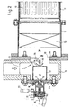
- the device of Figure 1 corresponds in its basic structure that of DE 37 29 861 C2 , A soot filter 10 is housed in a cylindrical housing 11, which is flowed through in the longitudinal direction of the engine exhaust.
- a mixer housing 12 which contains a mixer 13.
- a combustion chamber housing 14 is located in front of the mixer housing.
- the primary burner 15 is arranged axially in the combustion chamber housing in the end wall of the combustion chamber housing 14.
- This has a swirl air atomizing nozzle 16, which swirls the fuel-air mixture and injects it axially into a primary combustion chamber 27.
- An electrical ignition device 18 serves to ignite the gas mixture, so that in the primary combustion chamber 27, a rotating flame is formed, which starts from the swirl air atomizing nozzle 16.
- the swirl air atomizing nozzle 16 the fuel is supplied via a fuel line 20. Further, outside air which has been previously compressed is supplied via an air inlet 21.
- the amount of air and the amount of fuel can be adjusted by levers 22,23.
- the swirl air atomizing nozzle 16 includes an annular blade. The fuel is sprayed against the cutting edge.
- the swirling air which is supplied at low pressure of, for example, 20 to 100 mbar, flows past the annular cutting edge and ruptures the fuel film at the cutting edge into drops.
- the primary combustion chamber 27 is fed all the air through the nozzle. The large air flow allows a low atomizing pressure. This makes a wide range of control possible.
- the primary combustion chamber 27 has a peripheral wall 17 which extends over at least two-thirds of the length of the primary combustion chamber, from the end wall 24, closed is. In the last third are lateral outflow openings 25.
- the housing bottom 26 is closed in this embodiment.
- the primary burner 15 By the described design of the primary burner 15 is achieved in combination with the closed side wall 17, that in the primary combustion chamber, a controlled recirculation of the combustion gases takes place, wherein flow rolls arise. This has the consequence that a high stability range is achieved with different energy states of the primary burner 15. This contributes to the fact that the fuel is intimately mixed with the entirety of the air supplied to the primary burner. The primary burner thus ensures a large power control range, with the result that a stable operation is given in each state of the engine.
- the space surrounding the primary combustion chamber 27 is connected to a mixing chamber 38. This is bounded by an annular wall 29 which protrudes inwardly from the wall of the mixer housing 12 and has a central passage 30.
- the fuel supplied through the fuel inlet 35 burns by means of the oxygen contained in the engine exhaust gases in the secondary combustion chamber 28. Additional combustion air is not supplied to the secondary combustion chamber 28.
- a passage 33 leads to the mixing chamber 38. In the mixing chamber 38, the combustion gases from the primary combustion chamber 27 and the secondary combustion chamber 28 are mixed.
- the housing 17, which encloses the primary combustion chamber 27, in its housing bottom 26 has a central outflow opening 25a.
- the secondary combustion chamber 28 In the gas flow behind the outflow opening 25a is the secondary combustion chamber 28 with the fuel inlet 35, which is designed here as a swirl-air atomizing nozzle.
- the fuel line 36 leading to the fuel inlet 35 is routed through the annular wall 29 so that it is protected from heat from the annular wall.
- the secondary burner has an arcuate evaporator shell 39 which is spaced from the fuel inlet 35 and serves to vaporize the fuel still contained in the combustion gases.
Landscapes
- Engineering & Computer Science (AREA)
- Chemical & Material Sciences (AREA)
- Mechanical Engineering (AREA)
- General Engineering & Computer Science (AREA)
- Environmental & Geological Engineering (AREA)
- Combustion & Propulsion (AREA)
- Chemical Kinetics & Catalysis (AREA)
- Health & Medical Sciences (AREA)
- Toxicology (AREA)
- Processes For Solid Components From Exhaust (AREA)
- Exhaust Gas After Treatment (AREA)
- Incineration Of Waste (AREA)
Applications Claiming Priority (1)
| Application Number | Priority Date | Filing Date | Title |
|---|---|---|---|
| DE102005037969A DE102005037969A1 (de) | 2005-08-11 | 2005-08-11 | Vorrichtung zur Heißgaserzeugung im Abgasstrang eines Verbrennungsmotors |
Publications (2)
| Publication Number | Publication Date |
|---|---|
| EP1752633A1 true EP1752633A1 (fr) | 2007-02-14 |
| EP1752633B1 EP1752633B1 (fr) | 2009-06-24 |
Family
ID=37308991
Family Applications (1)
| Application Number | Title | Priority Date | Filing Date |
|---|---|---|---|
| EP06118536A Not-in-force EP1752633B1 (fr) | 2005-08-11 | 2006-08-07 | Appareil pour la génération de gaz chaud dans un système d'échappement d'un moteur thermique |
Country Status (3)
| Country | Link |
|---|---|
| EP (1) | EP1752633B1 (fr) |
| AT (1) | ATE434717T1 (fr) |
| DE (2) | DE102005037969A1 (fr) |
Cited By (1)
| Publication number | Priority date | Publication date | Assignee | Title |
|---|---|---|---|---|
| US9506385B2 (en) | 2010-07-15 | 2016-11-29 | Faurecia Emissions Control Technologies, Usa, Llc | Fuel fired burner for vehicle exhaust component |
Families Citing this family (3)
| Publication number | Priority date | Publication date | Assignee | Title |
|---|---|---|---|---|
| DE102008063515A1 (de) * | 2008-12-18 | 2010-06-24 | Deutz Ag | Verdampfer |
| DE102009023550A1 (de) * | 2009-05-30 | 2010-12-09 | Deutz Ag | Abgasnachbehandlungssystem |
| CN104564243A (zh) * | 2014-12-31 | 2015-04-29 | 杭州纯化科技有限公司 | 柴油发动机dpf低温再生点火器专用直管扰流器 |
Citations (4)
| Publication number | Priority date | Publication date | Assignee | Title |
|---|---|---|---|---|
| EP0306743A2 (fr) * | 1987-09-05 | 1989-03-15 | Deutsches Zentrum für Luft- und Raumfahrt e.V. | Procédé de filtrage de suie et filtre de suie pour un moteur diesel |
| EP0532044A1 (fr) * | 1991-09-12 | 1993-03-17 | Firma J. Eberspächer | Brûleur pour un filtre à particules de gaz d'échappement d'un moteur diesel |
| JPH08105608A (ja) * | 1994-09-30 | 1996-04-23 | Miura Kenkyusho:Kk | 触媒燃焼ボイラ |
| DE19504183A1 (de) * | 1995-02-09 | 1996-08-14 | Eberspaecher J | Brenner zur thermischen Regeneration eines Partikelfilters in einem Abgasnachbehandlungssystem eines Verbrennungsmotors, insbesondere Dieselmotors |
Family Cites Families (2)
| Publication number | Priority date | Publication date | Assignee | Title |
|---|---|---|---|---|
| DE3837472C2 (de) * | 1988-11-04 | 1998-09-24 | Deutz Ag | Partikelfiltersystem |
| DE4325906C2 (de) * | 1993-08-02 | 1995-08-24 | Daimler Benz Ag | Vorrichtung zur Regenerierung eines im Abgastrakt einer Brennkraftmaschine eingesezten Partikelfilters |
-
2005
- 2005-08-11 DE DE102005037969A patent/DE102005037969A1/de not_active Withdrawn
-
2006
- 2006-08-07 EP EP06118536A patent/EP1752633B1/fr not_active Not-in-force
- 2006-08-07 DE DE502006004051T patent/DE502006004051D1/de active Active
- 2006-08-07 AT AT06118536T patent/ATE434717T1/de active
Patent Citations (4)
| Publication number | Priority date | Publication date | Assignee | Title |
|---|---|---|---|---|
| EP0306743A2 (fr) * | 1987-09-05 | 1989-03-15 | Deutsches Zentrum für Luft- und Raumfahrt e.V. | Procédé de filtrage de suie et filtre de suie pour un moteur diesel |
| EP0532044A1 (fr) * | 1991-09-12 | 1993-03-17 | Firma J. Eberspächer | Brûleur pour un filtre à particules de gaz d'échappement d'un moteur diesel |
| JPH08105608A (ja) * | 1994-09-30 | 1996-04-23 | Miura Kenkyusho:Kk | 触媒燃焼ボイラ |
| DE19504183A1 (de) * | 1995-02-09 | 1996-08-14 | Eberspaecher J | Brenner zur thermischen Regeneration eines Partikelfilters in einem Abgasnachbehandlungssystem eines Verbrennungsmotors, insbesondere Dieselmotors |
Cited By (1)
| Publication number | Priority date | Publication date | Assignee | Title |
|---|---|---|---|---|
| US9506385B2 (en) | 2010-07-15 | 2016-11-29 | Faurecia Emissions Control Technologies, Usa, Llc | Fuel fired burner for vehicle exhaust component |
Also Published As
| Publication number | Publication date |
|---|---|
| EP1752633B1 (fr) | 2009-06-24 |
| ATE434717T1 (de) | 2009-07-15 |
| DE102005037969A1 (de) | 2007-02-15 |
| DE502006004051D1 (de) | 2009-08-06 |
Similar Documents
| Publication | Publication Date | Title |
|---|---|---|
| EP0367280B2 (fr) | Système de filtre de particules | |
| EP0902233B1 (fr) | Buse de pulvérisation par pression combinée | |
| DE69407545T2 (de) | Zweikraftstoffeinspritzdüse zum gebrauch in einem gasturbinentriebwerk | |
| DE69519197T2 (de) | Zerstäuber für die Verbrennung von flüssigem Brennstoff mit kleinem Sprühwinkel | |
| DE3729861C2 (de) | Verfahren zum Betreiben einer Rußfiltervorrichtung für einen Dieselmotor und Rußfiltervorrichtung zur Durchführung dieses Verfahrens | |
| DE3217674C2 (de) | Brennkammer für eine Gasturbine | |
| EP1802915B1 (fr) | Bruleur pour turbine a gaz | |
| EP0576697B1 (fr) | Chambre de combustion pour turbine à gaz | |
| EP1393002B1 (fr) | Procede et dispositif pour la combustion non catalytique peu polluante d'un combustible liquide | |
| DE19504183A1 (de) | Brenner zur thermischen Regeneration eines Partikelfilters in einem Abgasnachbehandlungssystem eines Verbrennungsmotors, insbesondere Dieselmotors | |
| EP1213536B1 (fr) | Brûleur à prémélange avec brûleur pilote catalytique | |
| EP0193838A2 (fr) | Disposition de brûleur pour installations de combustion, en particulier pour chambres de combustion d'installations de turbines à gaz ainsi que procédé de sa mise en oeuvre | |
| DE2901099A1 (de) | Kraftstoffverdampfungsvorrichtung, damit ausgeruestete brennkammer und verfahren zum betreiben derselben | |
| EP0438682A2 (fr) | Système d'échappement avec filtre à particules et brÀ»leur de régénération | |
| EP0598189A1 (fr) | Pulvérisateur pour un brûleur à huile | |
| EP1213541B1 (fr) | Brûleur à prémélange avec combustion catalytique et procédé de fonctionnement | |
| EP1999410B1 (fr) | Bruleur pour le fonctionnement d'un generateur de chaleur | |
| EP1864056B1 (fr) | Bruleur de premelange destine a une chambre de combustion de turbine a gaz | |
| DE10205573B4 (de) | Zerstäuberdüse für einen Brenner | |
| DE60224518T2 (de) | Vormischende turbinenverbrennungskammer | |
| EP0543323A2 (fr) | Brûleur pour fours industriels | |
| EP3663669B1 (fr) | Module de chambre de combustion | |
| DE1932881A1 (de) | Brennkammer | |
| EP1752633B1 (fr) | Appareil pour la génération de gaz chaud dans un système d'échappement d'un moteur thermique | |
| DE69318509T2 (de) | Verdampfungsbrenner |
Legal Events
| Date | Code | Title | Description |
|---|---|---|---|
| PUAI | Public reference made under article 153(3) epc to a published international application that has entered the european phase |
Free format text: ORIGINAL CODE: 0009012 |
|
| AK | Designated contracting states |
Kind code of ref document: A1 Designated state(s): AT BE BG CH CY CZ DE DK EE ES FI FR GB GR HU IE IS IT LI LT LU LV MC NL PL PT RO SE SI SK TR |
|
| AX | Request for extension of the european patent |
Extension state: AL BA HR MK YU |
|
| 17P | Request for examination filed |
Effective date: 20070705 |
|
| 17Q | First examination report despatched |
Effective date: 20070802 |
|
| AKX | Designation fees paid |
Designated state(s): AT BE BG CH CY CZ DE DK EE ES FI FR GB GR HU IE IS IT LI LT LU LV MC NL PL PT RO SE SI SK TR |
|
| GRAP | Despatch of communication of intention to grant a patent |
Free format text: ORIGINAL CODE: EPIDOSNIGR1 |
|
| RTI1 | Title (correction) |
Free format text: DEVICE FOR GENERATING A HOT GAS IN AN EXHAUST SYSTEM OF A COMBUSTION ENGINE |
|
| GRAS | Grant fee paid |
Free format text: ORIGINAL CODE: EPIDOSNIGR3 |
|
| GRAA | (expected) grant |
Free format text: ORIGINAL CODE: 0009210 |
|
| AK | Designated contracting states |
Kind code of ref document: B1 Designated state(s): AT BE BG CH CY CZ DE DK EE ES FI FR GB GR HU IE IS IT LI LT LU LV MC NL PL PT RO SE SI SK TR |
|
| REG | Reference to a national code |
Ref country code: GB Ref legal event code: FG4D Free format text: NOT ENGLISH |
|
| REG | Reference to a national code |
Ref country code: CH Ref legal event code: EP |
|
| REG | Reference to a national code |
Ref country code: CH Ref legal event code: NV Representative=s name: ISLER & PEDRAZZINI AG |
|
| REG | Reference to a national code |
Ref country code: IE Ref legal event code: FG4D Free format text: LANGUAGE OF EP DOCUMENT: GERMAN |
|
| REF | Corresponds to: |
Ref document number: 502006004051 Country of ref document: DE Date of ref document: 20090806 Kind code of ref document: P |
|
| PG25 | Lapsed in a contracting state [announced via postgrant information from national office to epo] |
Ref country code: FI Free format text: LAPSE BECAUSE OF FAILURE TO SUBMIT A TRANSLATION OF THE DESCRIPTION OR TO PAY THE FEE WITHIN THE PRESCRIBED TIME-LIMIT Effective date: 20090624 Ref country code: LT Free format text: LAPSE BECAUSE OF FAILURE TO SUBMIT A TRANSLATION OF THE DESCRIPTION OR TO PAY THE FEE WITHIN THE PRESCRIBED TIME-LIMIT Effective date: 20090624 |
|
| PG25 | Lapsed in a contracting state [announced via postgrant information from national office to epo] |
Ref country code: LV Free format text: LAPSE BECAUSE OF FAILURE TO SUBMIT A TRANSLATION OF THE DESCRIPTION OR TO PAY THE FEE WITHIN THE PRESCRIBED TIME-LIMIT Effective date: 20090624 Ref country code: SI Free format text: LAPSE BECAUSE OF FAILURE TO SUBMIT A TRANSLATION OF THE DESCRIPTION OR TO PAY THE FEE WITHIN THE PRESCRIBED TIME-LIMIT Effective date: 20090624 Ref country code: PL Free format text: LAPSE BECAUSE OF FAILURE TO SUBMIT A TRANSLATION OF THE DESCRIPTION OR TO PAY THE FEE WITHIN THE PRESCRIBED TIME-LIMIT Effective date: 20090624 Ref country code: SE Free format text: LAPSE BECAUSE OF FAILURE TO SUBMIT A TRANSLATION OF THE DESCRIPTION OR TO PAY THE FEE WITHIN THE PRESCRIBED TIME-LIMIT Effective date: 20090924 |
|
| NLV1 | Nl: lapsed or annulled due to failure to fulfill the requirements of art. 29p and 29m of the patents act | ||
| PG25 | Lapsed in a contracting state [announced via postgrant information from national office to epo] |
Ref country code: IS Free format text: LAPSE BECAUSE OF FAILURE TO SUBMIT A TRANSLATION OF THE DESCRIPTION OR TO PAY THE FEE WITHIN THE PRESCRIBED TIME-LIMIT Effective date: 20091024 Ref country code: ES Free format text: LAPSE BECAUSE OF FAILURE TO SUBMIT A TRANSLATION OF THE DESCRIPTION OR TO PAY THE FEE WITHIN THE PRESCRIBED TIME-LIMIT Effective date: 20091005 Ref country code: EE Free format text: LAPSE BECAUSE OF FAILURE TO SUBMIT A TRANSLATION OF THE DESCRIPTION OR TO PAY THE FEE WITHIN THE PRESCRIBED TIME-LIMIT Effective date: 20090624 Ref country code: CZ Free format text: LAPSE BECAUSE OF FAILURE TO SUBMIT A TRANSLATION OF THE DESCRIPTION OR TO PAY THE FEE WITHIN THE PRESCRIBED TIME-LIMIT Effective date: 20090624 |
|
| REG | Reference to a national code |
Ref country code: IE Ref legal event code: FD4D |
|
| PG25 | Lapsed in a contracting state [announced via postgrant information from national office to epo] |
Ref country code: SK Free format text: LAPSE BECAUSE OF FAILURE TO SUBMIT A TRANSLATION OF THE DESCRIPTION OR TO PAY THE FEE WITHIN THE PRESCRIBED TIME-LIMIT Effective date: 20090624 Ref country code: NL Free format text: LAPSE BECAUSE OF FAILURE TO SUBMIT A TRANSLATION OF THE DESCRIPTION OR TO PAY THE FEE WITHIN THE PRESCRIBED TIME-LIMIT Effective date: 20090624 |
|
| BERE | Be: lapsed |
Owner name: DEUTSCHES ZENTRUM FUR LUFT- UND RAUMFAHRT E.V. Effective date: 20090831 |
|
| PG25 | Lapsed in a contracting state [announced via postgrant information from national office to epo] |
Ref country code: BG Free format text: LAPSE BECAUSE OF FAILURE TO SUBMIT A TRANSLATION OF THE DESCRIPTION OR TO PAY THE FEE WITHIN THE PRESCRIBED TIME-LIMIT Effective date: 20090924 Ref country code: PT Free format text: LAPSE BECAUSE OF FAILURE TO SUBMIT A TRANSLATION OF THE DESCRIPTION OR TO PAY THE FEE WITHIN THE PRESCRIBED TIME-LIMIT Effective date: 20091024 Ref country code: MC Free format text: LAPSE BECAUSE OF NON-PAYMENT OF DUE FEES Effective date: 20090831 |
|
| PG25 | Lapsed in a contracting state [announced via postgrant information from national office to epo] |
Ref country code: DK Free format text: LAPSE BECAUSE OF FAILURE TO SUBMIT A TRANSLATION OF THE DESCRIPTION OR TO PAY THE FEE WITHIN THE PRESCRIBED TIME-LIMIT Effective date: 20090624 Ref country code: IE Free format text: LAPSE BECAUSE OF FAILURE TO SUBMIT A TRANSLATION OF THE DESCRIPTION OR TO PAY THE FEE WITHIN THE PRESCRIBED TIME-LIMIT Effective date: 20090624 |
|
| PLBE | No opposition filed within time limit |
Free format text: ORIGINAL CODE: 0009261 |
|
| STAA | Information on the status of an ep patent application or granted ep patent |
Free format text: STATUS: NO OPPOSITION FILED WITHIN TIME LIMIT |
|
| REG | Reference to a national code |
Ref country code: FR Ref legal event code: ST Effective date: 20100430 |
|
| 26N | No opposition filed |
Effective date: 20100325 |
|
| PG25 | Lapsed in a contracting state [announced via postgrant information from national office to epo] |
Ref country code: BE Free format text: LAPSE BECAUSE OF NON-PAYMENT OF DUE FEES Effective date: 20090831 |
|
| PG25 | Lapsed in a contracting state [announced via postgrant information from national office to epo] |
Ref country code: FR Free format text: LAPSE BECAUSE OF NON-PAYMENT OF DUE FEES Effective date: 20090831 |
|
| PG25 | Lapsed in a contracting state [announced via postgrant information from national office to epo] |
Ref country code: GR Free format text: LAPSE BECAUSE OF FAILURE TO SUBMIT A TRANSLATION OF THE DESCRIPTION OR TO PAY THE FEE WITHIN THE PRESCRIBED TIME-LIMIT Effective date: 20090925 |
|
| PG25 | Lapsed in a contracting state [announced via postgrant information from national office to epo] |
Ref country code: RO Free format text: LAPSE BECAUSE OF FAILURE TO SUBMIT A TRANSLATION OF THE DESCRIPTION OR TO PAY THE FEE WITHIN THE PRESCRIBED TIME-LIMIT Effective date: 20090624 |
|
| PG25 | Lapsed in a contracting state [announced via postgrant information from national office to epo] |
Ref country code: IT Free format text: LAPSE BECAUSE OF FAILURE TO SUBMIT A TRANSLATION OF THE DESCRIPTION OR TO PAY THE FEE WITHIN THE PRESCRIBED TIME-LIMIT Effective date: 20090624 |
|
| GBPC | Gb: european patent ceased through non-payment of renewal fee |
Effective date: 20100807 |
|
| PG25 | Lapsed in a contracting state [announced via postgrant information from national office to epo] |
Ref country code: LU Free format text: LAPSE BECAUSE OF NON-PAYMENT OF DUE FEES Effective date: 20090807 |
|
| PG25 | Lapsed in a contracting state [announced via postgrant information from national office to epo] |
Ref country code: HU Free format text: LAPSE BECAUSE OF FAILURE TO SUBMIT A TRANSLATION OF THE DESCRIPTION OR TO PAY THE FEE WITHIN THE PRESCRIBED TIME-LIMIT Effective date: 20091225 |
|
| PG25 | Lapsed in a contracting state [announced via postgrant information from national office to epo] |
Ref country code: GB Free format text: LAPSE BECAUSE OF NON-PAYMENT OF DUE FEES Effective date: 20100807 Ref country code: TR Free format text: LAPSE BECAUSE OF FAILURE TO SUBMIT A TRANSLATION OF THE DESCRIPTION OR TO PAY THE FEE WITHIN THE PRESCRIBED TIME-LIMIT Effective date: 20090624 |
|
| PG25 | Lapsed in a contracting state [announced via postgrant information from national office to epo] |
Ref country code: CY Free format text: LAPSE BECAUSE OF FAILURE TO SUBMIT A TRANSLATION OF THE DESCRIPTION OR TO PAY THE FEE WITHIN THE PRESCRIBED TIME-LIMIT Effective date: 20090624 |
|
| PGFP | Annual fee paid to national office [announced via postgrant information from national office to epo] |
Ref country code: DE Payment date: 20150831 Year of fee payment: 10 Ref country code: CH Payment date: 20150714 Year of fee payment: 10 |
|
| PGFP | Annual fee paid to national office [announced via postgrant information from national office to epo] |
Ref country code: AT Payment date: 20150727 Year of fee payment: 10 |
|
| REG | Reference to a national code |
Ref country code: DE Ref legal event code: R119 Ref document number: 502006004051 Country of ref document: DE |
|
| REG | Reference to a national code |
Ref country code: CH Ref legal event code: PL |
|
| REG | Reference to a national code |
Ref country code: AT Ref legal event code: MM01 Ref document number: 434717 Country of ref document: AT Kind code of ref document: T Effective date: 20160807 |
|
| PG25 | Lapsed in a contracting state [announced via postgrant information from national office to epo] |
Ref country code: CH Free format text: LAPSE BECAUSE OF NON-PAYMENT OF DUE FEES Effective date: 20160831 Ref country code: LI Free format text: LAPSE BECAUSE OF NON-PAYMENT OF DUE FEES Effective date: 20160831 |
|
| PG25 | Lapsed in a contracting state [announced via postgrant information from national office to epo] |
Ref country code: AT Free format text: LAPSE BECAUSE OF NON-PAYMENT OF DUE FEES Effective date: 20160807 |
|
| PG25 | Lapsed in a contracting state [announced via postgrant information from national office to epo] |
Ref country code: DE Free format text: LAPSE BECAUSE OF NON-PAYMENT OF DUE FEES Effective date: 20170301 |