EP0306895A2 - Procédé de fabrication d'un tuyau de mesure pour la mesure magnéto-inductive de débit - Google Patents
Procédé de fabrication d'un tuyau de mesure pour la mesure magnéto-inductive de débit Download PDFInfo
- Publication number
- EP0306895A2 EP0306895A2 EP88114525A EP88114525A EP0306895A2 EP 0306895 A2 EP0306895 A2 EP 0306895A2 EP 88114525 A EP88114525 A EP 88114525A EP 88114525 A EP88114525 A EP 88114525A EP 0306895 A2 EP0306895 A2 EP 0306895A2
- Authority
- EP
- European Patent Office
- Prior art keywords
- inner part
- outer part
- electrically conductive
- layers
- measuring tube
- Prior art date
- Legal status (The legal status is an assumption and is not a legal conclusion. Google has not performed a legal analysis and makes no representation as to the accuracy of the status listed.)
- Granted
Links
Images


Classifications
-
- G—PHYSICS
- G01—MEASURING; TESTING
- G01F—MEASURING VOLUME, VOLUME FLOW, MASS FLOW OR LIQUID LEVEL; METERING BY VOLUME
- G01F1/00—Measuring the volume flow or mass flow of fluid or fluent solid material wherein the fluid passes through a meter in a continuous flow
- G01F1/56—Measuring the volume flow or mass flow of fluid or fluent solid material wherein the fluid passes through a meter in a continuous flow by using electric or magnetic effects
- G01F1/58—Measuring the volume flow or mass flow of fluid or fluent solid material wherein the fluid passes through a meter in a continuous flow by using electric or magnetic effects by electromagnetic flowmeters
- G01F1/584—Measuring the volume flow or mass flow of fluid or fluent solid material wherein the fluid passes through a meter in a continuous flow by using electric or magnetic effects by electromagnetic flowmeters constructions of electrodes, accessories therefor
-
- G—PHYSICS
- G01—MEASURING; TESTING
- G01F—MEASURING VOLUME, VOLUME FLOW, MASS FLOW OR LIQUID LEVEL; METERING BY VOLUME
- G01F1/00—Measuring the volume flow or mass flow of fluid or fluent solid material wherein the fluid passes through a meter in a continuous flow
- G01F1/56—Measuring the volume flow or mass flow of fluid or fluent solid material wherein the fluid passes through a meter in a continuous flow by using electric or magnetic effects
- G01F1/58—Measuring the volume flow or mass flow of fluid or fluent solid material wherein the fluid passes through a meter in a continuous flow by using electric or magnetic effects by electromagnetic flowmeters
Definitions
- the invention relates to a method for producing a measuring tube for magnetic-inductive flow measurement.
- the measuring voltage occurring in the magnetic-inductive flow measurement is u. a. depending on the distance between the electrodes and the average flow velocity of the medium flowing through the measuring tube. These two sizes are significantly influenced by the geometric dimensions of the measuring tube, so that the highest possible stability should be aimed for.
- plastic generally has a high coefficient of thermal expansion as well as a low mechanical strength, particularly with respect to tension, pressure or shear.
- the metal sheathing should include the tubular plastic liner to stabilize the shape.
- the high coefficient of thermal expansion leads to a decrease in the volume of the inner lining.
- This shrinkage easily leads to an at least partial detachment of the inner lining from the metal casing and to permanent mechanical stresses in the plastic.
- the detachments change the geometric dimensions of the measuring tube cross section, which can lead to falsifications of the measuring voltages.
- the mechanical stresses that are not reduced increase the risk of cracks occurring in the plastic.
- the invention solves the problem of a simple and inexpensive manufacturing process drive for generic measuring tubes that have a high dimensional stability.
- the solution according to the invention consists of first forming a tubular inner part as an inner lining made of plastic. This can be done in particular by turning or milling a plastic blank or by injection molding. In the next step, the outer surface of the tubular inner part is at least partially provided with a material such that the inner part is surrounded by it and its shape is thus stabilized. This material forming the outer part is selected such that the outer part has a lower coefficient of thermal expansion and a higher mechanical strength than the inner part.
- the advantage achieved with the invention is that the inner part can relax mechanically freely after its formation. This largely avoids the likelihood of cracks occurring later in the material of the inner part. Furthermore, the inner part can sufficiently solidify in its relaxation phase. The subsequent application of the outer part therefore does not lead to any noticeable deformation of the inner part cross section.
- a special training is carried out the invention of the outer part by coating (see DIN 8580), in particular electroplating or plasma spraying, the inner part.
- Non-ferromagnetic material is preferably used as the coating material.
- the coating process ensures firm adhesion of the outer part to the plastic inner part.
- Preferred materials for the inner part are fluoroplastics, e.g. B. Teflon (PFA-perfluoroalkoxy) or Hostaflon (ETFE-ethylene tetrafluoroethylene), which can be coated particularly advantageously with copper or nickel. Coating processes, especially electroplating, can be used inexpensively for mass production.
- the outer part is composed of layers of different materials. This is done, for example, using various galvanic baths.
- functionally adapted areas e.g. B. for ferro-magnetic pole shoes
- chemically resistant electrodes with preferably capacitive tapping and the like can be created.
- areas of different conductivity and / or non-conductive areas can be created, which advantageously serve to obstruct eddy currents.
- FIGS. 1-5 denote corresponding parts.
- a magnetic-inductive flow meter is basically constructed as follows: an electrically conductive liquid, whose volumetric flow is to be determined, flows through a measuring tube 1 at the speed v.
- Two excitation coils 2, 3 through which the current I flows and which are operated with alternating or pulsating direct voltage generate a magnetic field B in the interior of the measuring tube 1.
- the induced voltage is tapped at two electrodes 4, 5 located in the wall of the measuring tube 1 are attached in isolation.
- the measuring tube 1 has an inner part 6 as a plastic inner lining and an outer part 7, preferably a stainless steel tube.
- the inner part 6 has the function of isolating the metallic outer part 7 from the electrically conductive flow medium.
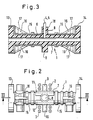
- Figures 2 and 3 the parts corresponding to Figure 1 are given the same reference numerals.
- FIG. 2 shows a measuring tube 1 produced according to the invention in a top view of an electrode pin 8, which is also to be provided with a bore in order to press an electrode 4 or 5 into it.
- a coil core 9 or 10 extends from the measuring tube 1 perpendicular to its longitudinal axis, around which the excitation coils 2 and 3 are wound.
- the excitation coils 2 and 3 also magnetize pole shoes 11 and 12, which are arranged between the inner part 6 and the outer part 7. This has the advantage that the pole shoes 11, 12 are located close to the flow medium to be measured and, as a result, the magnetic resistance is reduced.
- the ends of the measuring tube 1 are formed into fastening flanges 13 and 14, respectively. Groove-shaped depressions 15 are also embedded in the outward-facing surface of the measuring tube. According to FIG. 3, the measuring tube 1 is stiffened by flat webs 16, the outer edges 17 of which extend from the flanges 13, 14 to the outer surface of the measuring tube 1. It is further shown in FIG. 3 that shield sleeves 18 for the electrodes 4, 5 can be formed in a simple manner by partially removing the outer part 7 in the region of an electrode stud 8 and subsequently processing it.
- electrodes with a capacitive tap can advantageously be included in the manufacture of the measuring tube. This is illustrated in FIGS. 4 and 5, with FIG. 5 being an enlarged sectional representation according to the line VV in FIG. 4 that is not true to scale.
- a first, electrically conductive layer 41 is first applied to a section of the surface of the inner part 6 (indicated by a dotted line in FIG. 4).
- This first conductive layer 41 forms in measurement operation the one plate of a capacitor, the dielectric of which is the non-conductive inner part 6, and the other plate is the electrically conductive medium which flows in the direction of the arrow in FIG. 4 through the measuring tube 1.
- the first conductive layer 41 is then at least partially coated with a first electrically insulating layer 42, to which a second, electrically conductive layer 43 is then at least partially applied as a shield electrode, in particular against stray capacities. This is expediently placed at ground or earth potential, which can be done via a further conductive layer, not shown.
- the second conductive layer 43 is also coated with a second electrically insulating layer 44, the material for the shape-stabilizing outer part 7 can be z. B. copper can be used.
- the extent of the two insulating layers 42, 44 can optionally be limited to the areas formed by the first and / or second conductive layer 41 or 43 or can encompass the entire outer surface of the measuring tube 1. According to the special design according to FIGS.
- the first and second insulating layers 42 and 44 and the second conductive layer 43 each have recesses which are flush with one another and which together form an opening leading to the first conductive layer 41. This makes it easy to contact the first conductive layer 41 (measuring electrode).
- further electrically conductive and insulating layers can be applied. If at least one of the further conductive layers is set to, for example, ground or earth potential, the shielding of the measuring electrode improves - with simultaneous relief or electrical relaxation of the above shielding electrode.
- FIGS. 4 and 5 makes it clear that the manufacturing method according to the invention is particularly suitable for measuring tubes with capacitive electrodes. This is because the structure of capacitive electrodes is essentially formed by overlapping layers (dielectric, capacitor plate, insulation, shield electrode, etc.) which can easily be attached in connection with the invention.
Landscapes
- Physics & Mathematics (AREA)
- Electromagnetism (AREA)
- Fluid Mechanics (AREA)
- General Physics & Mathematics (AREA)
- Measuring Volume Flow (AREA)
Applications Claiming Priority (4)
| Application Number | Priority Date | Filing Date | Title |
|---|---|---|---|
| DE3730641 | 1987-09-11 | ||
| DE19873730641 DE3730641A1 (de) | 1987-09-11 | 1987-09-11 | Verfahren zur herstellung eines magnetisch-induktiven messrohres |
| DE3743371 | 1987-12-21 | ||
| DE3743371 | 1987-12-21 |
Publications (3)
| Publication Number | Publication Date |
|---|---|
| EP0306895A2 true EP0306895A2 (fr) | 1989-03-15 |
| EP0306895A3 EP0306895A3 (fr) | 1991-03-13 |
| EP0306895B1 EP0306895B1 (fr) | 1994-12-07 |
Family
ID=25859698
Family Applications (1)
| Application Number | Title | Priority Date | Filing Date |
|---|---|---|---|
| EP88114525A Expired - Lifetime EP0306895B1 (fr) | 1987-09-11 | 1988-09-06 | Procédé de fabrication d'un tuyau de mesure pour la mesure magnéto-inductive de débit |
Country Status (3)
| Country | Link |
|---|---|
| EP (1) | EP0306895B1 (fr) |
| JP (1) | JPH0625680B2 (fr) |
| DE (1) | DE3852360D1 (fr) |
Cited By (5)
| Publication number | Priority date | Publication date | Assignee | Title |
|---|---|---|---|---|
| EP0554059A3 (en) * | 1992-01-31 | 1995-08-09 | Tokyo Shibaura Electric Co | Electromagnetic flowmeter |
| GB2424955A (en) * | 2005-04-09 | 2006-10-11 | Siemens Ag | Flow meter with conductive coating |
| DE102012017904A1 (de) * | 2012-08-21 | 2014-03-20 | Krohne Ag | Magnetisch-induktives Durchflussmessgerät und Verfahren zu seiner Herstellung |
| US10712184B1 (en) | 2019-01-09 | 2020-07-14 | Georg Fischer Signet Llc | Magnetic flowmeter assembly having independent coil drive and control system |
| US11365995B2 (en) | 2018-09-28 | 2022-06-21 | Georg Fischer Signet Llc | Magnetic flowmeter including auxiliary electrodes upstream and downstream of the pair of measuring electrodes and an adjustable brace |
Families Citing this family (2)
| Publication number | Priority date | Publication date | Assignee | Title |
|---|---|---|---|---|
| DE10347890A1 (de) * | 2003-10-10 | 2005-05-04 | Abb Patent Gmbh | Magnetisch-induktives Messgerät für strömende Stoffe und Verfahren zu dessen Herstellung |
| KR100683821B1 (ko) * | 2005-07-21 | 2007-02-15 | 김정춘 | 스텐레스 304 또는 316 소재의 주물제 수도계량기 |
Family Cites Families (3)
| Publication number | Priority date | Publication date | Assignee | Title |
|---|---|---|---|---|
| DE2030263C3 (de) * | 1970-06-19 | 1981-07-16 | Josef Heinrichs Meßgerätebau, 5000 Köln | Rohrförmige Armatur mit einer Auskleidung aus Tetrafluoräthylen |
| US4329879A (en) * | 1980-07-14 | 1982-05-18 | Fischer & Porter Co. | Insulating liner for electromagnetic flowmeter tube |
| DE3337151A1 (de) * | 1983-10-12 | 1985-04-25 | Fischer & Porter GmbH, 3400 Göttingen | Induktiver durchflussmesser |
-
1988
- 1988-09-06 EP EP88114525A patent/EP0306895B1/fr not_active Expired - Lifetime
- 1988-09-06 DE DE3852360T patent/DE3852360D1/de not_active Expired - Fee Related
- 1988-09-09 JP JP63224853A patent/JPH0625680B2/ja not_active Expired - Lifetime
Cited By (8)
| Publication number | Priority date | Publication date | Assignee | Title |
|---|---|---|---|---|
| EP0554059A3 (en) * | 1992-01-31 | 1995-08-09 | Tokyo Shibaura Electric Co | Electromagnetic flowmeter |
| GB2424955A (en) * | 2005-04-09 | 2006-10-11 | Siemens Ag | Flow meter with conductive coating |
| GB2424955B (en) * | 2005-04-09 | 2008-07-16 | Siemens Ag | Flow meter with conductive coating |
| DE102012017904A1 (de) * | 2012-08-21 | 2014-03-20 | Krohne Ag | Magnetisch-induktives Durchflussmessgerät und Verfahren zu seiner Herstellung |
| US9121740B2 (en) | 2012-08-21 | 2015-09-01 | Krohne Ag | Magnetic-inductive flow meter and method for its production |
| US9829359B2 (en) | 2012-08-21 | 2017-11-28 | Krohne Ag | Method for production of a magnetic-inductive flow meter |
| US11365995B2 (en) | 2018-09-28 | 2022-06-21 | Georg Fischer Signet Llc | Magnetic flowmeter including auxiliary electrodes upstream and downstream of the pair of measuring electrodes and an adjustable brace |
| US10712184B1 (en) | 2019-01-09 | 2020-07-14 | Georg Fischer Signet Llc | Magnetic flowmeter assembly having independent coil drive and control system |
Also Published As
| Publication number | Publication date |
|---|---|
| EP0306895B1 (fr) | 1994-12-07 |
| DE3852360D1 (de) | 1995-01-19 |
| JPH0625680B2 (ja) | 1994-04-06 |
| EP0306895A3 (fr) | 1991-03-13 |
| JPH01221618A (ja) | 1989-09-05 |
Similar Documents
| Publication | Publication Date | Title |
|---|---|---|
| DE4017260C2 (de) | Verfahren zum Herstellen einer Sattelspulen-Anordnung für ein Gradientenmagnetfeld einer MRI-Apparatur | |
| EP1039269B1 (fr) | Procédé de fabrication d'un capteur électromagnétique de débit | |
| DE102015116771B4 (de) | Verfahren zum Einstellen einer konstanten Magnetfeldstärke eines Magnetfelds bei einem magnetisch-induktiven Durchflussmessgerät und diesbezügliches magnetisch-induktives Durchflussmessgerät | |
| EP3814725B1 (fr) | Débitmètre à induction magnétique et procédé de fabrication d'un tel débitmètre à induction magnétique | |
| EP0764831A1 (fr) | Procédé de fabrication d'un tube de mesure pour un capteur électromagnétique de débit | |
| DE102015116679A1 (de) | Magnetisch-induktives Durchflussmessgerät | |
| DE19856123A1 (de) | Hohlisolator | |
| EP3815473B1 (fr) | Sonde de mesure de paramètres plasmatiques par spectroscopie de résonance plasmatique active | |
| EP0306895A2 (fr) | Procédé de fabrication d'un tuyau de mesure pour la mesure magnéto-inductive de débit | |
| EP1756531A1 (fr) | Capteur de debit a induction magnetique | |
| DE3730641A1 (de) | Verfahren zur herstellung eines magnetisch-induktiven messrohres | |
| EP1692465B1 (fr) | Capteur de debit magneto-inductif et procede de fabrication | |
| DE10358268A1 (de) | Magnetisch-induktiver Durchflußaufnehmer und Verfahren zu dessen Herstellung | |
| DE19705436C2 (de) | Meßrohranordnung für elektromagnetische Durchflußmesser und Verfahren zu ihrer Herstellung | |
| DE102008038162A1 (de) | Durchflussmesseinrichtung, sowie Verfahren zur Herstellung derselben | |
| DE2946866A1 (de) | Aufzeichnungskopf fuer elektrostatische aufzeichnungsgeraete und verfahren zu seiner herstellung | |
| DE102015107119A1 (de) | Messrohr und Magnetisch-induktives Durchflussmessgerät | |
| DE102015116676A1 (de) | Magnetisch-induktives Durchflussmessgerät und Verfahren zum Herstellen einer Messelektrode | |
| EP3048431B1 (fr) | Débitmètre magnéto-inductif et procédé de fabrication d'une électrode de mesure | |
| DE202005021377U1 (de) | Elektrische Spule | |
| DE102018108021B4 (de) | Leitungsanordnung und Verfahren zum Herstellen einer Leitungsanordnung | |
| DE102022118729A1 (de) | Magnetisch-induktives Durchflussmessgerät | |
| DE102005004406A1 (de) | Elektrische Spule | |
| DE3234699A1 (de) | Flexibler hohlleiter fuer millimeterwellen sowie verfahren zur herstellung eines solchen | |
| DE102022211150A1 (de) | Herstellungsverfahren für einen Hochfrequenzhohlleiter |
Legal Events
| Date | Code | Title | Description |
|---|---|---|---|
| PUAI | Public reference made under article 153(3) epc to a published international application that has entered the european phase |
Free format text: ORIGINAL CODE: 0009012 |
|
| AK | Designated contracting states |
Kind code of ref document: A2 Designated state(s): CH DE FR GB IT LI NL |
|
| EL | Fr: translation of claims filed | ||
| GBC | Gb: translation of claims filed (gb section 78(7)/1977) | ||
| ITCL | It: translation for ep claims filed |
Representative=s name: STUDIO TORTA SOCIETA' SEMPLICE |
|
| TCNL | Nl: translation of patent claims filed | ||
| PUAL | Search report despatched |
Free format text: ORIGINAL CODE: 0009013 |
|
| 17P | Request for examination filed |
Effective date: 19901203 |
|
| AK | Designated contracting states |
Kind code of ref document: A3 Designated state(s): CH DE FR GB IT LI NL |
|
| RAP1 | Party data changed (applicant data changed or rights of an application transferred) |
Owner name: ENDRESS + HAUSER FLOWTEC AG |
|
| 17Q | First examination report despatched |
Effective date: 19921214 |
|
| GRAA | (expected) grant |
Free format text: ORIGINAL CODE: 0009210 |
|
| AK | Designated contracting states |
Kind code of ref document: B1 Designated state(s): CH DE FR GB IT LI NL |
|
| ITF | It: translation for a ep patent filed | ||
| REF | Corresponds to: |
Ref document number: 3852360 Country of ref document: DE Date of ref document: 19950119 |
|
| ET | Fr: translation filed | ||
| GBT | Gb: translation of ep patent filed (gb section 77(6)(a)/1977) |
Effective date: 19950308 |
|
| PLBE | No opposition filed within time limit |
Free format text: ORIGINAL CODE: 0009261 |
|
| STAA | Information on the status of an ep patent application or granted ep patent |
Free format text: STATUS: NO OPPOSITION FILED WITHIN TIME LIMIT |
|
| 26N | No opposition filed | ||
| PGFP | Annual fee paid to national office [announced via postgrant information from national office to epo] |
Ref country code: GB Payment date: 20000814 Year of fee payment: 13 |
|
| PGFP | Annual fee paid to national office [announced via postgrant information from national office to epo] |
Ref country code: CH Payment date: 20000816 Year of fee payment: 13 |
|
| PGFP | Annual fee paid to national office [announced via postgrant information from national office to epo] |
Ref country code: NL Payment date: 20000824 Year of fee payment: 13 |
|
| PGFP | Annual fee paid to national office [announced via postgrant information from national office to epo] |
Ref country code: DE Payment date: 20000830 Year of fee payment: 13 |
|
| PGFP | Annual fee paid to national office [announced via postgrant information from national office to epo] |
Ref country code: FR Payment date: 20000831 Year of fee payment: 13 |
|
| PG25 | Lapsed in a contracting state [announced via postgrant information from national office to epo] |
Ref country code: GB Free format text: LAPSE BECAUSE OF NON-PAYMENT OF DUE FEES Effective date: 20010906 |
|
| PG25 | Lapsed in a contracting state [announced via postgrant information from national office to epo] |
Ref country code: LI Free format text: LAPSE BECAUSE OF NON-PAYMENT OF DUE FEES Effective date: 20010930 Ref country code: CH Free format text: LAPSE BECAUSE OF NON-PAYMENT OF DUE FEES Effective date: 20010930 |
|
| PG25 | Lapsed in a contracting state [announced via postgrant information from national office to epo] |
Ref country code: NL Free format text: LAPSE BECAUSE OF NON-PAYMENT OF DUE FEES Effective date: 20020401 |
|
| PG25 | Lapsed in a contracting state [announced via postgrant information from national office to epo] |
Ref country code: DE Free format text: LAPSE BECAUSE OF NON-PAYMENT OF DUE FEES Effective date: 20020501 |
|
| REG | Reference to a national code |
Ref country code: CH Ref legal event code: PL |
|
| PG25 | Lapsed in a contracting state [announced via postgrant information from national office to epo] |
Ref country code: FR Free format text: LAPSE BECAUSE OF NON-PAYMENT OF DUE FEES Effective date: 20020531 |
|
| NLV4 | Nl: lapsed or anulled due to non-payment of the annual fee |
Effective date: 20020401 |
|
| REG | Reference to a national code |
Ref country code: FR Ref legal event code: ST |
|
| NLV4 | Nl: lapsed or anulled due to non-payment of the annual fee |
Effective date: 20020401 |
|
| PG25 | Lapsed in a contracting state [announced via postgrant information from national office to epo] |
Ref country code: IT Free format text: LAPSE BECAUSE OF NON-PAYMENT OF DUE FEES;WARNING: LAPSES OF ITALIAN PATENTS WITH EFFECTIVE DATE BEFORE 2007 MAY HAVE OCCURRED AT ANY TIME BEFORE 2007. THE CORRECT EFFECTIVE DATE MAY BE DIFFERENT FROM THE ONE RECORDED. Effective date: 20050906 |