EP0306966B1 - Ablenkmagnet - Google Patents
Ablenkmagnet Download PDFInfo
- Publication number
- EP0306966B1 EP0306966B1 EP88114762A EP88114762A EP0306966B1 EP 0306966 B1 EP0306966 B1 EP 0306966B1 EP 88114762 A EP88114762 A EP 88114762A EP 88114762 A EP88114762 A EP 88114762A EP 0306966 B1 EP0306966 B1 EP 0306966B1
- Authority
- EP
- European Patent Office
- Prior art keywords
- orbit
- circumference side
- bending
- charged particle
- outer circumference
- Prior art date
- Legal status (The legal status is an assumption and is not a legal conclusion. Google has not performed a legal analysis and makes no representation as to the accuracy of the status listed.)
- Expired - Lifetime
Links
Images


Classifications
-
- H—ELECTRICITY
- H05—ELECTRIC TECHNIQUES NOT OTHERWISE PROVIDED FOR
- H05H—PLASMA TECHNIQUE; PRODUCTION OF ACCELERATED ELECTRICALLY-CHARGED PARTICLES OR OF NEUTRONS; PRODUCTION OR ACCELERATION OF NEUTRAL MOLECULAR OR ATOMIC BEAMS
- H05H7/00—Details of devices of the types covered by groups H05H9/00, H05H11/00, H05H13/00
- H05H7/04—Magnet systems, e.g. undulators, wigglers; Energisation thereof
Definitions
- This invention relates to a bending magnet according to the preamble portion of claim 1.
- Such a bending magnet is disclosed in Japanese patent unexamined publication JP-A-61-80800.
- This example intends to generate a strong magnetic field of about 3 teslas, and has an iron core having upper and lower magnetic poles and upper and lower superconducting coils wound on the upper and lower poles, respectively.
- the iron core encloses the overall length of the coils.
- the super-conducting coils generate a strong magnetizing force by which the magnetic poles are strongly saturated.
- the bending magnetic field is stronger on the outer circumference side than on the inner circumference side to produce a magnetic field which causes the charged particle beam to diverge in a direction perpendicular to the orbital plane of the charged particle beam.
- the bending magnetic field is weaker on the outer circumference side than on the inner circumference side to produce a magnetic field which causes the charged particle beam to converge in the aforementioned direction.
- the magnetic field on the inner circumference side is equal to that on the outer circumference side and the bending magnetic field becomes uniform. Accordingly, the bending magnet per se is effective to converge or diverge the charged particle beam and is suitable for realization of a strongly focusing type synchrotron or storage ring removed of quadrupole magnet.
- the vertical distance h1 between the inner circumference side coil segments is made to be equal to the vertical distance h2 between the outer circumference side coil segments for the purpose of obtaining the uniform bending magnetic field.
- the prior art coil arrangement is unsuitable for the bending magnet.
- the prior art suggests a coil arrangement of making the vertical distance between inner circumference side coil segments different from the vertical distance between outer circumference side coil segments for causing the magnetic field to converge or diverge but nothing about improvement of uniformity of magnetic field.
- the prior art in no way takes into account improving the uniformity of magnetic field over the overall length of the orbit of charged particle beam in the bending magnet.
- JP-A-62-186500 and JP-A-62-140400 also disclose a superconducting bending magnet, but none of these publications suggests nothing about the above problem to be solved by the present invention.
- the present invention contemplates elimination of the prior art drawbacks and has for its object to provide a bending magnet which can generate a strong and uniform bending magnetic field over the overall length of the orbit of charged particle beam even when the bending magnet has the form of a sector or semi-circle.
- this object is achieved by a bending magnet according to claim 1.
- Figs. 1 and 2 illustrate a bending magnet according to an embodiment of the invention.
- a pair of opposed cryostats 6 each incorporating a superconducting coil are placed in a cavity formed in a core 1 maintained at normal temperature and an upper superconducting coil having segments 2a and 2a′ (hereinafter referred to as an upper superconducting coil 2a, 2a′) and a lower superconducting coil having segments 2b and 2b′ (hereinafter referred to as a lower superconducting coil 2b, 2b′) are so disposed as to be symmetrical with respect to the orbital plane of a charged particle beam 5.
- a vertical distance h2 between the coil segments 2a′ and 2b′ of the upper and lower superconducting coils disposed at the outer circumference side of the orbit of the charged particle beam 5 is made to be larger than a vertical distance h1 between the coil segments 2a and 2b of the upper and lower superconducting coils disposed at the inner circumference side of the orbit, and the horizontal width of a return yoke 7b disposed at the outer circumference side of the orbit is made to be smaller than that of a return yoke 7a disposed at the inner circumference side of the orbit so that the sectional configuration of the inner circumference side return yoke and the sectional configuration of the outer circumference side return yoke are asymmetrical with respect to the center line of the magnetic poles.
- the magnetic flux density is equally uniformed in the inner and outer circumference side return yokes 7a and 7b and in a magnetic circuit of the bending magnet, the magnetic flux undergoes the same reluctance in the inner and outer circumference side return yokes 7a and 7b.
- Magnetic poles 3a and 3b oppose to each other through a gap in the core 1 maintained at normal temperature and the magnetic circuit comprised of the core 1 and upper superconducting coil 2a, 2a′ and lower superconducting coil 2b, 2b′ generates a bending magnetic field in the gap between the magnetic poles 3a and 3b.
- a vacuum chamber 4 is disposed in the gap and the charged particle beam 5 circulates through the vacuum chamber.
- Fig. 2 shows a sectional structure of the bending magnet having a bending angle of 90° for the charged particle beam 5.
- the bending angle may be any angle obtained by dividing 360° by an integer n which is 2 or more.
- n may preferably approximate 2 or 4.
- the sectional configuration of the core 1 is sectoral and the arcuate vacuum chamber 4 through which the charged particle beam 5 circulates is disposed in the gap formed centrally of the iron core 1.
- the sectional configuration of each of the inner and outer circumference side return yokes 7a and 7b is also sectoral.
- the coil segments constituting each of the upper superconducting coil 2a, 2a′ and the lower super-conducting coil 2b, 2b′ are connected, together with cryostat 6, at opposite ends of the bending magnet and the connecting portions are bent up or down so as not to interfere spatially with the vacuum chamber 4.
- the magnetic flux passing through the inner and outer circumference side return yokes can be equally uniformed over the overall length in the orbital direction of the charged particle beam 5 by widening the vertical distance between the outer circumference side coil segments 2a′ and 2b′ in order to uniform the magnetic flux distribution of the bending magnetic field generated in the gap between magnetic poles 3a and 3b where the magnetic flux passing through the inner and outer circumference side return yokes is concentrated. In this manner, the adverse influence due to non-uniformity of bending magnetic field upon the charged particle beam can be eliminated.
- the charged particle beam can be 90° bent under the influence of a strong bending magnetic field generated by the superconducting coils.
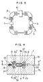
- FIG. 3 An example of a storage ring using the bending magnets is illustrated in Fig. 3.
- reference numeral 8 designates the bending magnet in accordance with the above embodiment, 9 a septum magnet by which the charged particle beam is injected, 10 a radio frequency cavity for accelerating the charged particle beam, 16 a quadrupole magnet for focus or defocus of the charged particle beam 5, and 11 a kicker magnet which is a pulse magnet adapted to make easy the injection of the charged particle beam 5 by slightly shifting the orbit of the charged particle beam 5.
- Fig. 3 An example of a storage ring using the bending magnets. 3.
- 9 a septum magnet by which the charged particle beam is injected
- 10 a radio frequency cavity for accelerating the charged particle beam
- 16 a quadrupole magnet for focus or defocus of the charged particle beam
- 11 a kicker magnet which is a pulse magnet adapted to make
- the storage ring using the superconducting bending magnets according to the invention to make the bending magnetic field strong can store a charged particle beam 5 having energy which is higher by an increased bending magnetic field than that stored in a storage ring of the same scale based on normal conductivity. Accordingly, by adopting the bending magnets according to the present embodiment, a synchrotron or storage ring of charged particle beam with the sectoral superconducting bending magnets can be provided by which a charged particle beam having energy which is higher than that obtained by a synchrotron or storage ring of the same scale based on normal conducting bending magnets can be accelerated or stored.
- This embodiment is directed to a bending magnet for an electron synchrotron or storage ring, particularly, in consideration of an application in which the accelerator is used as a synchrotron radiation (SR) source.
- SR synchrotron radiation
- this embodiment differs from the Fig. 1 embodiment in that tunnels 15 are formed in the outer circumference side return yoke vertically centrally thereof i.e. on a plane containing the orbit of charged particle beam, and guide ducts 14 for radiations 13 radiating tangentially to the orbit of a charged particle beam 12 are provided in the tunnels 15.
- the vertical distance h2 between superconducting coil segments 2a′ and 2b′ disposed at the outer circumference side of the orbit of charged particle beam 12 is made to be larger than the vertical distance, h1, between superconducting coil segments 2a and 2b disposed at the inner circumference side of the orbit to equally uniform the magnetic flux passing through the inner and outer circumference side return yokes.
- a uniform bending magnetic field can be generated in the gap between magnetic poles 3a and 3b for the same reason as in the case of the previous embodiment and besides, a gap can be formed between the cryostats 6 containing the upper and lower coil segments, respectively, disposed at the outer circumference side of the orbit so that the radiation guide ducts 14 can extend to the outside of the core 1 through the gap.
- Fig. 5 shows a sectional structure of the bending magnet having a bending angle of 90° for the charged particle beam.
- the value of bending angle is determined similarly to the foregoing embodiment, that is, by dividing 360° by a relatively small integer which is 2 or more and may be different from 90°.
- two radiation guide ducts 14 extend from a vacuum chamber 4 disposed in the bending magnet.
- the radiation guide ducts 14 pass through the tunnels 15 in the outer circumference side return yoke 7b tangentially to the orbit of the charged particle beam 12 so as to extend to the outside of a core 1.
- the inner walls of the radiation guide duct 14 perpendicular to the charged particle orbit are parallel to the tangents of the orbit of charged particle beam 12 in order to decrease the amount of gas discharged from the inner wall under irradiation of the radiation 13.
- the number of radiation guide ducts 14 may be three or more but must be determined so as not to lead to magnetic saturation of the outer circumference side return yoke 7b and to a great difference in reluctance between the inner and outer circumference side return yokes 7a and 7b in the magnetic circuit comprised of the upper superconducting coil 2a, 2a′, lower superconducting coil 2b, 2b′ and core 1.
- Figs. 4 and 5 are all capable of generating a uniform bending magnetic field in the gap between magnetic poles 3a and 3b but the kind of charged particle beam to be used differs depending on the application, that is, acceleration or storage as will be described below in brief.
- E o 511 KeV holds for an electron
- the electron beam energy approximating a few hundred of MeV or more is a sufficiently high relativistic energy value to obtain ⁇ ⁇ a few thousand, and with the electron the bending magnet can be utilized for a synchrotron radiation source.
- the bending magnet in accordance with the embodiment of Figs. 1 and 2 which is removed of radiation guide duct 14 can be utilized as a superconducting bending magnet with a sectoral core which is used with a weighty charged particle such as a proton.
- This embodiment adds to the bending magnet of the embodiment shown in Figs. 4 and 5 such a feature that upstream of the orbit of the charged particle beam 12, a plurality of tunnels 15 are provided in which no radiation guide duct 14 is disposed.
- the cross-sectional structure of the outer circumference side return yoke 7b can be uniformed circumferentially to improve uniformity of the distribution of bending magnetic field in the orbital direction of the charged particle beam.
- values of the vertical distance h1 between the inner circumference side superconducting coil segments 2a and 2b and the vertical distance h2 between the outer circumference side superconducting coil segments 2a′ and 2b′ are determined as will be described below.
- the vertical distance h1 between the inner circumference side superconducting coil segments 2a and 2b is determined by making 30° or less an angle ( ⁇ ) subtended by a horizontal line 20 passing the charged particle beam 5 and a line connecting the charged particle beam 5 and the center of inner circumference side superconducting coil segment 2a or 2b and by taking into consideration cooling characteristics of the superconducting coil segments 2a and 2b. It has experimentally proven that for ⁇ being 30° or less, the magnetic field can be uniform using the superconducting coils.
- the vertical distance h2 between the outer circumference side superconducting coil segments 2a′ and 2b′ is approximately determined through calculation by reflecting the determined vertical distance h1 between the inner circumference side superconducting coil segments 2a and 2b. Since the radiation guide duct extends through a gap between the upper and lower cryostat segments in the outer circumference side return yoke, the vertical distance h2 is necessarily required to be larger than the diameter of the duct. To precisely determine the vertical distance h1, after the inner radius of the coil is determined in consideration of ambient conditions (such as the size of the magnetic pole), the approximate value based on the calculation is corrected by adjusting the position of the coil segments 2a and 2b vertically.
- the magnetic flux in the vacuum chamber can be distributed uniformly in the radial direction of the bending magnet and over the overall length of the orbit of the charged particle beam and in essentiality, any expedient for making the magnetic flux distribution in the vacuum chamber uniform in the radial direction of the bending magnet and over the overall orbital length of the charged particle beam can be within the framework of the present invention.
- a bending magnet comprising a core which is substantially sectoral or semi-circular in horizontally sectional configuration and in which opposed magnetic poles are formed and a vacuum chamber for storage of a charged particle beam is disposed in a gap between the opposed magnetic poles, and a pair of upper and lower exciting coils for generating a bending magnetic field in the gap between the magnetic poles of core, the reluctance against the magnetic flux passing through a portion of the core adjacent to the inner circumference of the orbit of the charged particle beam and a portion of the core adjacent to the outer circumference of the charged particle beam orbit is equally uniformed over the overall length of the orbit of the charged particle beam.
- the magnetic flux density becomes uniform in the gap between magnetic poles where the magnetic flux passing through the inner and outer circumference side portions is concentrated and the magnetic flux distribution is uniformed in the orbital direction in the gap, thereby eliminating adverse influence upon the charged particle beam, and the bending magnet can be very effective for use in the synchrotron and storage ring.
Landscapes
- Physics & Mathematics (AREA)
- Optics & Photonics (AREA)
- Engineering & Computer Science (AREA)
- Plasma & Fusion (AREA)
- Spectroscopy & Molecular Physics (AREA)
- Particle Accelerators (AREA)
Claims (4)
- Ablenkmagnet zum Ablenken eines durch eine Vakuumkammer (4) zirkulierenden Strahls geladener Teilchen (5), mit:
einem Kern (1), der in horizontalem Querschnitt im wesentlichen sektor- oder halbkreisförmig ist und mit entgegengesetzten Magnetpolen (3a, 3b) so ausgebildet ist, daß die Vakuumkammer in einem Spalt zwischen den entgegengesetzten Magnetpolen liegt; und
einem Paar von oberen und unteren supraleitenden Erregerspulen (2a, 2a′; 2b, 2b′) zum Erzeugen eines Ablenkmagnetes im Spalt;
dadurch gekennzeichnet, daß
das Paar von oberen und unteren Erregerspulen (2a, 2b; 2a′, 2b′) eine vertikale Querschnittskonfiguration hat, die auf der ganzen Länge des Ablenkmagneten in Richtung der Umlaufbahn asymmetrisch in Bezug auf eine die Umlaufbahn vertikal schneidene Linie ist, so daß ein in der vertikalen Querschnittskonfiguration außerhalb des Umfangs der Umlaufbahn gemessener vertikaler Abstand zwischen oberer und unterer Erregerspule größer ist als ein in der vertikalen Querschnittsanordnung innerhalb des Umfangs der Umlaufbahn gemessener vertikaler Abstand zwischen oberer und unterer Erregerspule ist, um so die Verteilung des im Spalt erzeugten magnetischen Flusses auf der ganzen Länge des Ablenkmagneten gleichförmig zu machen. - Ablenkmagnet nach Anspruch 1, dadurch gekennzeichnet, daß daß der Kern (1) ein erstes Rückführjoch (7b), das dem äußeren Umfang der der Umlaufbahn benachbart ist, und ein zweites Rückführjoch (7a), das dem inneren Umfang der Bahn benachbart ist, umfaßt, und daß die horizontale Breite des ersten Rückführjochs (7b) kleiner als die horizontale Breite des zweiten Rückführjochs (7a) ist.
- Ablenkmagnet nach Anspruch 1, dadurch gekennzeichnet, daß wenigstens ein Tunnel (15) in einem Abschnitt (7b) des Kerns (1) des äußeren Umfangs der Umlaufbahn benachbart gebildet ist, um einen dadurch verlaufenden Synchrotronstrahlführungskanal (14) zu montieren, und daß der Tunnel (15) zwischen den zwei dem äußeren Umfang der Umlaufbahn benachbarten Segmenten (2a′, 2b′) der oberen und unteren Erregerspulen verläuft und mit der Vakuumkammer (4) in Verbindung steht.
- Ablenkmagnet nach Anspruch 3, dadurch gekennzeichnet, daß eine Mehrzahl solcher Tunnel (15) in einem Rückführjoch (7b) des Kerns (1) dem äußeren Umfang der Umlaufbahn benachbart gebildet sind, so daß sie im wesentlichen gleichförmig in Richtung der Umlaufbahn des Strahls geladener Teilchen verteilt sind.
Applications Claiming Priority (2)
| Application Number | Priority Date | Filing Date | Title |
|---|---|---|---|
| JP62226362A JP2667832B2 (ja) | 1987-09-11 | 1987-09-11 | 偏向マグネット |
| JP226362/87 | 1987-09-11 |
Publications (3)
| Publication Number | Publication Date |
|---|---|
| EP0306966A2 EP0306966A2 (de) | 1989-03-15 |
| EP0306966A3 EP0306966A3 (en) | 1990-01-17 |
| EP0306966B1 true EP0306966B1 (de) | 1995-04-05 |
Family
ID=16843958
Family Applications (1)
| Application Number | Title | Priority Date | Filing Date |
|---|---|---|---|
| EP88114762A Expired - Lifetime EP0306966B1 (de) | 1987-09-11 | 1988-09-09 | Ablenkmagnet |
Country Status (4)
| Country | Link |
|---|---|
| US (1) | US4996496A (de) |
| EP (1) | EP0306966B1 (de) |
| JP (1) | JP2667832B2 (de) |
| DE (1) | DE3853507T2 (de) |
Cited By (13)
| Publication number | Priority date | Publication date | Assignee | Title |
|---|---|---|---|---|
| US7728311B2 (en) | 2005-11-18 | 2010-06-01 | Still River Systems Incorporated | Charged particle radiation therapy |
| US8003964B2 (en) | 2007-10-11 | 2011-08-23 | Still River Systems Incorporated | Applying a particle beam to a patient |
| US8581523B2 (en) | 2007-11-30 | 2013-11-12 | Mevion Medical Systems, Inc. | Interrupted particle source |
| US8791656B1 (en) | 2013-05-31 | 2014-07-29 | Mevion Medical Systems, Inc. | Active return system |
| US8927950B2 (en) | 2012-09-28 | 2015-01-06 | Mevion Medical Systems, Inc. | Focusing a particle beam |
| US8933650B2 (en) | 2007-11-30 | 2015-01-13 | Mevion Medical Systems, Inc. | Matching a resonant frequency of a resonant cavity to a frequency of an input voltage |
| US8952634B2 (en) | 2004-07-21 | 2015-02-10 | Mevion Medical Systems, Inc. | Programmable radio frequency waveform generator for a synchrocyclotron |
| US9155186B2 (en) | 2012-09-28 | 2015-10-06 | Mevion Medical Systems, Inc. | Focusing a particle beam using magnetic field flutter |
| US9185789B2 (en) | 2012-09-28 | 2015-11-10 | Mevion Medical Systems, Inc. | Magnetic shims to alter magnetic fields |
| US9301384B2 (en) | 2012-09-28 | 2016-03-29 | Mevion Medical Systems, Inc. | Adjusting energy of a particle beam |
| US9545528B2 (en) | 2012-09-28 | 2017-01-17 | Mevion Medical Systems, Inc. | Controlling particle therapy |
| US9962560B2 (en) | 2013-12-20 | 2018-05-08 | Mevion Medical Systems, Inc. | Collimator and energy degrader |
| US10258810B2 (en) | 2013-09-27 | 2019-04-16 | Mevion Medical Systems, Inc. | Particle beam scanning |
Families Citing this family (80)
| Publication number | Priority date | Publication date | Assignee | Title |
|---|---|---|---|---|
| EP0542737A1 (de) * | 1990-08-06 | 1993-05-26 | Siemens Aktiengesellschaft | Synchrotronstrahlungsquelle |
| JPH04112499A (ja) * | 1990-08-31 | 1992-04-14 | Mitsubishi Electric Corp | Sor装置用真空槽 |
| US5374913A (en) * | 1991-12-13 | 1994-12-20 | Houston Advanced Research Center | Twin-bore flux pipe dipole magnet |
| US5576602A (en) * | 1993-08-18 | 1996-11-19 | Hitachi, Ltd. | Method for extracting charged particle beam and small-sized accelerator for charged particle beam |
| JPH09115698A (ja) * | 1995-10-17 | 1997-05-02 | Rikagaku Kenkyusho | サイクロトロンの磁場調整用中心棒 |
| JP3488915B2 (ja) * | 2001-03-08 | 2004-01-19 | 高エネルギー加速器研究機構長 | ビーム偏向分離用セプタム電磁石、ビーム偏向分離用電磁石、及びビーム偏向方法 |
| RU2265974C1 (ru) * | 2004-04-05 | 2005-12-10 | Государственное научное учреждение "Научно-исследовательский институт интроскопии при Томском политехническом университете Министерства образования Российской Федерации" | Безжелезный синхротрон |
| US8969834B2 (en) | 2008-05-22 | 2015-03-03 | Vladimir Balakin | Charged particle therapy patient constraint apparatus and method of use thereof |
| US9744380B2 (en) | 2008-05-22 | 2017-08-29 | Susan L. Michaud | Patient specific beam control assembly of a cancer therapy apparatus and method of use thereof |
| US9855444B2 (en) | 2008-05-22 | 2018-01-02 | Scott Penfold | X-ray detector for proton transit detection apparatus and method of use thereof |
| US9177751B2 (en) | 2008-05-22 | 2015-11-03 | Vladimir Balakin | Carbon ion beam injector apparatus and method of use thereof |
| US9737272B2 (en) | 2008-05-22 | 2017-08-22 | W. Davis Lee | Charged particle cancer therapy beam state determination apparatus and method of use thereof |
| US8129699B2 (en) | 2008-05-22 | 2012-03-06 | Vladimir Balakin | Multi-field charged particle cancer therapy method and apparatus coordinated with patient respiration |
| US10070831B2 (en) | 2008-05-22 | 2018-09-11 | James P. Bennett | Integrated cancer therapy—imaging apparatus and method of use thereof |
| US8975600B2 (en) | 2008-05-22 | 2015-03-10 | Vladimir Balakin | Treatment delivery control system and method of operation thereof |
| US9682254B2 (en) | 2008-05-22 | 2017-06-20 | Vladimir Balakin | Cancer surface searing apparatus and method of use thereof |
| US8642978B2 (en) | 2008-05-22 | 2014-02-04 | Vladimir Balakin | Charged particle cancer therapy dose distribution method and apparatus |
| US9737734B2 (en) | 2008-05-22 | 2017-08-22 | Susan L. Michaud | Charged particle translation slide control apparatus and method of use thereof |
| US9168392B1 (en) | 2008-05-22 | 2015-10-27 | Vladimir Balakin | Charged particle cancer therapy system X-ray apparatus and method of use thereof |
| US9044600B2 (en) * | 2008-05-22 | 2015-06-02 | Vladimir Balakin | Proton tomography apparatus and method of operation therefor |
| US9782140B2 (en) | 2008-05-22 | 2017-10-10 | Susan L. Michaud | Hybrid charged particle / X-ray-imaging / treatment apparatus and method of use thereof |
| US9910166B2 (en) | 2008-05-22 | 2018-03-06 | Stephen L. Spotts | Redundant charged particle state determination apparatus and method of use thereof |
| US9616252B2 (en) | 2008-05-22 | 2017-04-11 | Vladimir Balakin | Multi-field cancer therapy apparatus and method of use thereof |
| US10092776B2 (en) | 2008-05-22 | 2018-10-09 | Susan L. Michaud | Integrated translation/rotation charged particle imaging/treatment apparatus and method of use thereof |
| US10029122B2 (en) | 2008-05-22 | 2018-07-24 | Susan L. Michaud | Charged particle—patient motion control system apparatus and method of use thereof |
| US9981147B2 (en) | 2008-05-22 | 2018-05-29 | W. Davis Lee | Ion beam extraction apparatus and method of use thereof |
| US8907309B2 (en) | 2009-04-17 | 2014-12-09 | Stephen L. Spotts | Treatment delivery control system and method of operation thereof |
| US9937362B2 (en) | 2008-05-22 | 2018-04-10 | W. Davis Lee | Dynamic energy control of a charged particle imaging/treatment apparatus and method of use thereof |
| US9579525B2 (en) | 2008-05-22 | 2017-02-28 | Vladimir Balakin | Multi-axis charged particle cancer therapy method and apparatus |
| US10684380B2 (en) | 2008-05-22 | 2020-06-16 | W. Davis Lee | Multiple scintillation detector array imaging apparatus and method of use thereof |
| US8624528B2 (en) * | 2008-05-22 | 2014-01-07 | Vladimir Balakin | Method and apparatus coordinating synchrotron acceleration periods with patient respiration periods |
| US10143854B2 (en) | 2008-05-22 | 2018-12-04 | Susan L. Michaud | Dual rotation charged particle imaging / treatment apparatus and method of use thereof |
| US9095040B2 (en) | 2008-05-22 | 2015-07-28 | Vladimir Balakin | Charged particle beam acceleration and extraction method and apparatus used in conjunction with a charged particle cancer therapy system |
| US9737733B2 (en) | 2008-05-22 | 2017-08-22 | W. Davis Lee | Charged particle state determination apparatus and method of use thereof |
| US10548551B2 (en) | 2008-05-22 | 2020-02-04 | W. Davis Lee | Depth resolved scintillation detector array imaging apparatus and method of use thereof |
| US9155911B1 (en) | 2008-05-22 | 2015-10-13 | Vladimir Balakin | Ion source method and apparatus used in conjunction with a charged particle cancer therapy system |
| US9974978B2 (en) | 2008-05-22 | 2018-05-22 | W. Davis Lee | Scintillation array apparatus and method of use thereof |
| US8718231B2 (en) | 2008-05-22 | 2014-05-06 | Vladimir Balakin | X-ray tomography method and apparatus used in conjunction with a charged particle cancer therapy system |
| US9498649B2 (en) | 2008-05-22 | 2016-11-22 | Vladimir Balakin | Charged particle cancer therapy patient constraint apparatus and method of use thereof |
| US9056199B2 (en) | 2008-05-22 | 2015-06-16 | Vladimir Balakin | Charged particle treatment, rapid patient positioning apparatus and method of use thereof |
| US10589128B2 (en) | 2010-04-16 | 2020-03-17 | Susan L. Michaud | Treatment beam path verification in a cancer therapy apparatus and method of use thereof |
| US20200227227A1 (en) * | 2010-04-16 | 2020-07-16 | Vladimir Balakin | Charged particle cancer therapy and patient positioning method and apparatus |
| US10518109B2 (en) | 2010-04-16 | 2019-12-31 | Jillian Reno | Transformable charged particle beam path cancer therapy apparatus and method of use thereof |
| US10086214B2 (en) | 2010-04-16 | 2018-10-02 | Vladimir Balakin | Integrated tomography—cancer treatment apparatus and method of use thereof |
| US10349906B2 (en) | 2010-04-16 | 2019-07-16 | James P. Bennett | Multiplexed proton tomography imaging apparatus and method of use thereof |
| US10376717B2 (en) | 2010-04-16 | 2019-08-13 | James P. Bennett | Intervening object compensating automated radiation treatment plan development apparatus and method of use thereof |
| US10188877B2 (en) | 2010-04-16 | 2019-01-29 | W. Davis Lee | Fiducial marker/cancer imaging and treatment apparatus and method of use thereof |
| US10625097B2 (en) | 2010-04-16 | 2020-04-21 | Jillian Reno | Semi-automated cancer therapy treatment apparatus and method of use thereof |
| US10638988B2 (en) | 2010-04-16 | 2020-05-05 | Scott Penfold | Simultaneous/single patient position X-ray and proton imaging apparatus and method of use thereof |
| US9737731B2 (en) | 2010-04-16 | 2017-08-22 | Vladimir Balakin | Synchrotron energy control apparatus and method of use thereof |
| US10555710B2 (en) | 2010-04-16 | 2020-02-11 | James P. Bennett | Simultaneous multi-axes imaging apparatus and method of use thereof |
| US11648420B2 (en) | 2010-04-16 | 2023-05-16 | Vladimir Balakin | Imaging assisted integrated tomography—cancer treatment apparatus and method of use thereof |
| US10556126B2 (en) | 2010-04-16 | 2020-02-11 | Mark R. Amato | Automated radiation treatment plan development apparatus and method of use thereof |
| US10179250B2 (en) | 2010-04-16 | 2019-01-15 | Nick Ruebel | Auto-updated and implemented radiation treatment plan apparatus and method of use thereof |
| US10751551B2 (en) | 2010-04-16 | 2020-08-25 | James P. Bennett | Integrated imaging-cancer treatment apparatus and method of use thereof |
| JP5587150B2 (ja) * | 2010-11-30 | 2014-09-10 | 株式会社日立製作所 | 磁場制御装置 |
| JP5665721B2 (ja) * | 2011-02-28 | 2015-02-04 | 三菱電機株式会社 | 円形加速器および円形加速器の運転方法 |
| US8963112B1 (en) | 2011-05-25 | 2015-02-24 | Vladimir Balakin | Charged particle cancer therapy patient positioning method and apparatus |
| US10254739B2 (en) | 2012-09-28 | 2019-04-09 | Mevion Medical Systems, Inc. | Coil positioning system |
| CN104813749B (zh) | 2012-09-28 | 2019-07-02 | 梅维昂医疗系统股份有限公司 | 控制粒子束的强度 |
| CN108770178B (zh) | 2012-09-28 | 2021-04-16 | 迈胜医疗设备有限公司 | 磁场再生器 |
| WO2014052721A1 (en) | 2012-09-28 | 2014-04-03 | Mevion Medical Systems, Inc. | Control system for a particle accelerator |
| US8933651B2 (en) | 2012-11-16 | 2015-01-13 | Vladimir Balakin | Charged particle accelerator magnet apparatus and method of use thereof |
| EP2785154B1 (de) * | 2013-03-29 | 2015-10-21 | Ion Beam Applications S.A. | Kompaktes supraleitendes Zyklotron |
| US9730308B2 (en) | 2013-06-12 | 2017-08-08 | Mevion Medical Systems, Inc. | Particle accelerator that produces charged particles having variable energies |
| US10675487B2 (en) | 2013-12-20 | 2020-06-09 | Mevion Medical Systems, Inc. | Energy degrader enabling high-speed energy switching |
| US9661736B2 (en) | 2014-02-20 | 2017-05-23 | Mevion Medical Systems, Inc. | Scanning system for a particle therapy system |
| JP6328487B2 (ja) * | 2014-05-20 | 2018-05-23 | 住友重機械工業株式会社 | 超伝導電磁石及び荷電粒子線治療装置 |
| JP2015225871A (ja) * | 2014-05-26 | 2015-12-14 | 住友重機械工業株式会社 | 超伝導電磁石装置及び荷電粒子線治療装置 |
| US9950194B2 (en) | 2014-09-09 | 2018-04-24 | Mevion Medical Systems, Inc. | Patient positioning system |
| US10786689B2 (en) | 2015-11-10 | 2020-09-29 | Mevion Medical Systems, Inc. | Adaptive aperture |
| CN105469926B (zh) * | 2015-12-30 | 2018-09-04 | 中国科学院等离子体物理研究所 | 适用于超导旋转机架技术的高温超导弯曲磁体结构 |
| US9907981B2 (en) | 2016-03-07 | 2018-03-06 | Susan L. Michaud | Charged particle translation slide control apparatus and method of use thereof |
| US10037863B2 (en) | 2016-05-27 | 2018-07-31 | Mark R. Amato | Continuous ion beam kinetic energy dissipater apparatus and method of use thereof |
| EP3481503B1 (de) | 2016-07-08 | 2021-04-21 | Mevion Medical Systems, Inc. | Behandlungsplanung |
| US11103730B2 (en) | 2017-02-23 | 2021-08-31 | Mevion Medical Systems, Inc. | Automated treatment in particle therapy |
| JP6940676B2 (ja) | 2017-06-30 | 2021-09-29 | メビオン・メディカル・システムズ・インコーポレーテッド | リニアモーターを使用して制御される構成可能コリメータ |
| JP7311620B2 (ja) | 2019-03-08 | 2023-07-19 | メビオン・メディカル・システムズ・インコーポレーテッド | 粒子線治療システムのためのコリメータおよびエネルギーデグレーダ |
| CN111341518B (zh) * | 2020-02-28 | 2021-11-09 | 合肥中科离子医学技术装备有限公司 | 一种磁场环境老化锻炼装置 |
| CN113382530B (zh) * | 2021-07-22 | 2023-11-10 | 中国科学院上海高等研究院 | 一种超高剂量率医用质子同步加速器 |
Family Cites Families (12)
| Publication number | Priority date | Publication date | Assignee | Title |
|---|---|---|---|---|
| US4200844A (en) * | 1976-12-13 | 1980-04-29 | Varian Associates | Racetrack microtron beam extraction system |
| GB8421867D0 (en) * | 1984-08-29 | 1984-10-03 | Oxford Instr Ltd | Devices for accelerating electrons |
| JPS6180800A (ja) * | 1984-09-28 | 1986-04-24 | 株式会社日立製作所 | 放射光照射装置 |
| JPH06103640B2 (ja) * | 1985-12-13 | 1994-12-14 | 三菱電機株式会社 | 荷電ビ−ム装置 |
| DE3704442A1 (de) * | 1986-02-12 | 1987-08-13 | Mitsubishi Electric Corp | Ladungstraegerstrahlvorrichtung |
| JPS62186500A (ja) * | 1986-02-12 | 1987-08-14 | 三菱電機株式会社 | 荷電ビ−ム装置 |
| DE3703938A1 (de) * | 1986-02-12 | 1987-09-10 | Mitsubishi Electric Corp | Teilchenbeschleuniger |
| US4806871A (en) * | 1986-05-23 | 1989-02-21 | Mitsubishi Denki Kabushiki Kaisha | Synchrotron |
| FR2607345B1 (fr) * | 1986-05-27 | 1993-02-05 | Mitsubishi Electric Corp | Synchrotron |
| US4853640A (en) * | 1987-02-12 | 1989-08-01 | Hitachi, Ltd. | Synchrotron radiation source |
| JPH0763036B2 (ja) * | 1987-03-11 | 1995-07-05 | 日本電信電話株式会社 | リタ−ンヨ−ク付き偏向電磁石 |
| DE3887996T2 (de) * | 1987-03-18 | 1994-08-11 | Hitachi Eng Service | Synchrotron-Strahlungsquelle. |
-
1987
- 1987-09-11 JP JP62226362A patent/JP2667832B2/ja not_active Expired - Lifetime
-
1988
- 1988-09-09 US US07/242,126 patent/US4996496A/en not_active Expired - Fee Related
- 1988-09-09 DE DE3853507T patent/DE3853507T2/de not_active Expired - Fee Related
- 1988-09-09 EP EP88114762A patent/EP0306966B1/de not_active Expired - Lifetime
Cited By (19)
| Publication number | Priority date | Publication date | Assignee | Title |
|---|---|---|---|---|
| US8952634B2 (en) | 2004-07-21 | 2015-02-10 | Mevion Medical Systems, Inc. | Programmable radio frequency waveform generator for a synchrocyclotron |
| US8344340B2 (en) | 2005-11-18 | 2013-01-01 | Mevion Medical Systems, Inc. | Inner gantry |
| US9452301B2 (en) | 2005-11-18 | 2016-09-27 | Mevion Medical Systems, Inc. | Inner gantry |
| US8907311B2 (en) | 2005-11-18 | 2014-12-09 | Mevion Medical Systems, Inc. | Charged particle radiation therapy |
| US8916843B2 (en) | 2005-11-18 | 2014-12-23 | Mevion Medical Systems, Inc. | Inner gantry |
| US7728311B2 (en) | 2005-11-18 | 2010-06-01 | Still River Systems Incorporated | Charged particle radiation therapy |
| US8003964B2 (en) | 2007-10-11 | 2011-08-23 | Still River Systems Incorporated | Applying a particle beam to a patient |
| US8941083B2 (en) | 2007-10-11 | 2015-01-27 | Mevion Medical Systems, Inc. | Applying a particle beam to a patient |
| US8970137B2 (en) | 2007-11-30 | 2015-03-03 | Mevion Medical Systems, Inc. | Interrupted particle source |
| US8581523B2 (en) | 2007-11-30 | 2013-11-12 | Mevion Medical Systems, Inc. | Interrupted particle source |
| US8933650B2 (en) | 2007-11-30 | 2015-01-13 | Mevion Medical Systems, Inc. | Matching a resonant frequency of a resonant cavity to a frequency of an input voltage |
| US9155186B2 (en) | 2012-09-28 | 2015-10-06 | Mevion Medical Systems, Inc. | Focusing a particle beam using magnetic field flutter |
| US8927950B2 (en) | 2012-09-28 | 2015-01-06 | Mevion Medical Systems, Inc. | Focusing a particle beam |
| US9185789B2 (en) | 2012-09-28 | 2015-11-10 | Mevion Medical Systems, Inc. | Magnetic shims to alter magnetic fields |
| US9301384B2 (en) | 2012-09-28 | 2016-03-29 | Mevion Medical Systems, Inc. | Adjusting energy of a particle beam |
| US9545528B2 (en) | 2012-09-28 | 2017-01-17 | Mevion Medical Systems, Inc. | Controlling particle therapy |
| US8791656B1 (en) | 2013-05-31 | 2014-07-29 | Mevion Medical Systems, Inc. | Active return system |
| US10258810B2 (en) | 2013-09-27 | 2019-04-16 | Mevion Medical Systems, Inc. | Particle beam scanning |
| US9962560B2 (en) | 2013-12-20 | 2018-05-08 | Mevion Medical Systems, Inc. | Collimator and energy degrader |
Also Published As
| Publication number | Publication date |
|---|---|
| JP2667832B2 (ja) | 1997-10-27 |
| EP0306966A2 (de) | 1989-03-15 |
| DE3853507T2 (de) | 1995-08-31 |
| JPS6472499A (en) | 1989-03-17 |
| DE3853507D1 (de) | 1995-05-11 |
| EP0306966A3 (en) | 1990-01-17 |
| US4996496A (en) | 1991-02-26 |
Similar Documents
| Publication | Publication Date | Title |
|---|---|---|
| EP0306966B1 (de) | Ablenkmagnet | |
| US5101169A (en) | Synchrotron radiation apparatus | |
| US5117212A (en) | Electromagnet for charged-particle apparatus | |
| KR100442990B1 (ko) | 중첩정적및시변자계를생성하는시스템및방법 | |
| JPH0746640B2 (ja) | シンクロトロン | |
| JPH10233299A (ja) | 荷電粒子ビームエキスパンダー | |
| JPS61294800A (ja) | 荷電粒子加速又は貯蔵設備の磁場装置 | |
| JPH06501334A (ja) | シンクロトロン放射源 | |
| US3344357A (en) | Storage ring | |
| US3387241A (en) | Permanent magnet multipole magnetic lens with variable convergence | |
| US3303426A (en) | Strong focusing of high energy particles in a synchrotron storage ring | |
| JPH0992498A (ja) | 挿入光源装置用磁気回路 | |
| JP4000555B2 (ja) | 周期磁場発生装置 | |
| JP3204920B2 (ja) | 永久磁石型偏向磁石装置および電子蓄積リング | |
| Togawa | Effect of solenoid lens field on electron beam emittance | |
| US3681599A (en) | Sector-type charged particle energy analyzer | |
| JPH02174099A (ja) | 超電導偏向電磁石 | |
| JP3652927B2 (ja) | 耐放射線特性を有する挿入光源 | |
| Robinson et al. | Field certification of a high strength tapered hybrid undulator | |
| JPS63224230A (ja) | X線露光装置 | |
| Hutcheon et al. | A new compact doubly achromatic asymmetric two-magnet beam deflection system | |
| Leupold et al. | Toroidal electron beam radiation sources | |
| JP2935082B2 (ja) | 常電導磁石型電子蓄積リング | |
| SU766550A1 (ru) | Мультипольна линза с круговой апертурой | |
| JPH03141615A (ja) | 固塊鉄心電磁石 |
Legal Events
| Date | Code | Title | Description |
|---|---|---|---|
| PUAI | Public reference made under article 153(3) epc to a published international application that has entered the european phase |
Free format text: ORIGINAL CODE: 0009012 |
|
| AK | Designated contracting states |
Kind code of ref document: A2 Designated state(s): CH DE FR GB LI SE |
|
| PUAL | Search report despatched |
Free format text: ORIGINAL CODE: 0009013 |
|
| AK | Designated contracting states |
Kind code of ref document: A3 Designated state(s): CH DE FR GB LI SE |
|
| 17P | Request for examination filed |
Effective date: 19900119 |
|
| 17Q | First examination report despatched |
Effective date: 19920722 |
|
| GRAA | (expected) grant |
Free format text: ORIGINAL CODE: 0009210 |
|
| AK | Designated contracting states |
Kind code of ref document: B1 Designated state(s): CH DE FR GB LI SE |
|
| RIN1 | Information on inventor provided before grant (corrected) |
Inventor name: UNO, YASUMICHI Inventor name: NAKATA, JOJI Inventor name: MAKI, NAOKI Inventor name: YAMAGUCHI, KIYOSHI Inventor name: TOMEOKU, HIROSHI Inventor name: KAKIUCHI, SHUNJI Inventor name: KOBAYASHI, TAKASHI Inventor name: KITAMURA, MASASHI |
|
| REF | Corresponds to: |
Ref document number: 3853507 Country of ref document: DE Date of ref document: 19950511 |
|
| ET | Fr: translation filed | ||
| PLBE | No opposition filed within time limit |
Free format text: ORIGINAL CODE: 0009261 |
|
| STAA | Information on the status of an ep patent application or granted ep patent |
Free format text: STATUS: NO OPPOSITION FILED WITHIN TIME LIMIT |
|
| 26N | No opposition filed | ||
| PGFP | Annual fee paid to national office [announced via postgrant information from national office to epo] |
Ref country code: FR Payment date: 20000718 Year of fee payment: 13 |
|
| PGFP | Annual fee paid to national office [announced via postgrant information from national office to epo] |
Ref country code: SE Payment date: 20000807 Year of fee payment: 13 |
|
| PGFP | Annual fee paid to national office [announced via postgrant information from national office to epo] |
Ref country code: GB Payment date: 20000830 Year of fee payment: 13 |
|
| PGFP | Annual fee paid to national office [announced via postgrant information from national office to epo] |
Ref country code: DE Payment date: 20001130 Year of fee payment: 13 |
|
| PGFP | Annual fee paid to national office [announced via postgrant information from national office to epo] |
Ref country code: CH Payment date: 20001212 Year of fee payment: 13 |
|
| PG25 | Lapsed in a contracting state [announced via postgrant information from national office to epo] |
Ref country code: GB Free format text: LAPSE BECAUSE OF NON-PAYMENT OF DUE FEES Effective date: 20010909 |
|
| PG25 | Lapsed in a contracting state [announced via postgrant information from national office to epo] |
Ref country code: SE Free format text: LAPSE BECAUSE OF NON-PAYMENT OF DUE FEES Effective date: 20010910 |
|
| PG25 | Lapsed in a contracting state [announced via postgrant information from national office to epo] |
Ref country code: LI Free format text: LAPSE BECAUSE OF NON-PAYMENT OF DUE FEES Effective date: 20010930 Ref country code: CH Free format text: LAPSE BECAUSE OF NON-PAYMENT OF DUE FEES Effective date: 20010930 |
|
| GBPC | Gb: european patent ceased through non-payment of renewal fee |
Effective date: 20010909 |
|
| PG25 | Lapsed in a contracting state [announced via postgrant information from national office to epo] |
Ref country code: DE Free format text: LAPSE BECAUSE OF NON-PAYMENT OF DUE FEES Effective date: 20020501 |
|
| EUG | Se: european patent has lapsed |
Ref document number: 88114762.3 |
|
| REG | Reference to a national code |
Ref country code: CH Ref legal event code: PL |
|
| PG25 | Lapsed in a contracting state [announced via postgrant information from national office to epo] |
Ref country code: FR Free format text: LAPSE BECAUSE OF NON-PAYMENT OF DUE FEES Effective date: 20020531 |
|
| REG | Reference to a national code |
Ref country code: FR Ref legal event code: ST |