EP0307069B1 - Einweg-Zell-Membranpumpe - Google Patents
Einweg-Zell-Membranpumpe Download PDFInfo
- Publication number
- EP0307069B1 EP0307069B1 EP88303654A EP88303654A EP0307069B1 EP 0307069 B1 EP0307069 B1 EP 0307069B1 EP 88303654 A EP88303654 A EP 88303654A EP 88303654 A EP88303654 A EP 88303654A EP 0307069 B1 EP0307069 B1 EP 0307069B1
- Authority
- EP
- European Patent Office
- Prior art keywords
- walls
- diaphragm
- cell
- wall
- split housing
- Prior art date
- Legal status (The legal status is an assumption and is not a legal conclusion. Google has not performed a legal analysis and makes no representation as to the accuracy of the status listed.)
- Expired - Lifetime
Links
- 210000004027 cell Anatomy 0.000 claims abstract description 64
- 210000002421 cell wall Anatomy 0.000 claims abstract description 8
- 230000002093 peripheral effect Effects 0.000 claims description 16
- 239000000853 adhesive Substances 0.000 claims description 2
- 230000001070 adhesive effect Effects 0.000 claims description 2
- 239000011248 coating agent Substances 0.000 claims 1
- 238000000576 coating method Methods 0.000 claims 1
- 239000012530 fluid Substances 0.000 abstract description 8
- 230000037452 priming Effects 0.000 description 10
- 230000000740 bleeding effect Effects 0.000 description 3
- 239000012790 adhesive layer Substances 0.000 description 2
- 238000011109 contamination Methods 0.000 description 2
- 238000001802 infusion Methods 0.000 description 2
- 238000000034 method Methods 0.000 description 2
- 230000002572 peristaltic effect Effects 0.000 description 2
- 238000010586 diagram Methods 0.000 description 1
- 230000000694 effects Effects 0.000 description 1
- 230000008030 elimination Effects 0.000 description 1
- 238000003379 elimination reaction Methods 0.000 description 1
- 230000005484 gravity Effects 0.000 description 1
- 239000007788 liquid Substances 0.000 description 1
- 239000000463 material Substances 0.000 description 1
- 238000000926 separation method Methods 0.000 description 1
Images


Classifications
-
- F—MECHANICAL ENGINEERING; LIGHTING; HEATING; WEAPONS; BLASTING
- F04—POSITIVE - DISPLACEMENT MACHINES FOR LIQUIDS; PUMPS FOR LIQUIDS OR ELASTIC FLUIDS
- F04B—POSITIVE-DISPLACEMENT MACHINES FOR LIQUIDS; PUMPS
- F04B43/00—Machines, pumps, or pumping installations having flexible working members
- F04B43/0009—Special features
- F04B43/0054—Special features particularities of the flexible members
-
- F—MECHANICAL ENGINEERING; LIGHTING; HEATING; WEAPONS; BLASTING
- F04—POSITIVE - DISPLACEMENT MACHINES FOR LIQUIDS; PUMPS FOR LIQUIDS OR ELASTIC FLUIDS
- F04B—POSITIVE-DISPLACEMENT MACHINES FOR LIQUIDS; PUMPS
- F04B43/00—Machines, pumps, or pumping installations having flexible working members
- F04B43/02—Machines, pumps, or pumping installations having flexible working members having plate-like flexible members, e.g. diaphragms
- F04B43/04—Pumps having electric drive
-
- F—MECHANICAL ENGINEERING; LIGHTING; HEATING; WEAPONS; BLASTING
- F04—POSITIVE - DISPLACEMENT MACHINES FOR LIQUIDS; PUMPS FOR LIQUIDS OR ELASTIC FLUIDS
- F04B—POSITIVE-DISPLACEMENT MACHINES FOR LIQUIDS; PUMPS
- F04B43/00—Machines, pumps, or pumping installations having flexible working members
- F04B43/02—Machines, pumps, or pumping installations having flexible working members having plate-like flexible members, e.g. diaphragms
- F04B43/06—Pumps having fluid drive
Definitions
- the present invention relates to a disposable cell for a diaphragm-actuated fluid-transfer control device, facilitating the passing therethrough, in dependence on the material the cell is made of, of any fluid, without the device either contaminating the fluid or being contaminated thereby.
- such devices are means to include diaphragm pumps as well as diaphragm valves.
- U.S. Patent 4,290,346 discloses a relatively simple pump chamber cassette which, however, is of limited use only, being specifically designed to be utilized in conjunction with an infusion set comprising a peristaltic pump. In fact, it can hardly be used for any other purpose, as this cassette allows of no positive suction stroke and will only work when the liquid is supplied to it by gravity, as is indeed the case with an infusion set, in which the I.V. solution container is located at the highest point of the system.
- a disposable cell for mounting inside a diaphragm-actuated, positive-suction and expulsion fluid-transfer control device having a split housing comprised of two substantially contiguous halves, with said cell being clamped at its periphery between a peripheral zone of one half of said split housing and a peripheral zone of said diaphragm, comprising two cell walls permanently and fluid-tightly joined to one another at their periphery, at least one of said walls being flexible, said at least one wall being adapted to be flexed from a first position, in which it is located in close proximity to the other wall, reducing the space enclosed by said two walls, to at least a second position, in which at least some regions of said at least one wall have moved away from said other wall, thereby increasing said space between said two walls, and an inlet port and an outlet port provided in at least one of said walls, whereby said cell further comprises an inlet valve communicating with said inlet port and an outlet valve communicating with said outlet port, and, in the mounted
- the invention further provides, in a diaphragm-actuated, positive-suction and expulsion stroke fluid-transfer control device having a split housing constituted by two substantially contiguous halves, an improvement comprising a disposable cell for mounting inside said split housing, being clamped at its periphery between a peripheral zone of one half of said split housing and a peripheral zone of said diaphragm, said cell having two cell walls permanently and fluid-tightly joined to one another at the periphery, at least one of which walls is flexible, at least one of said walls being attachable to, and capable of participating in the movement of, said diaphragm, said one wall being adapted to be flexed from a first position, in which it is located in close proximity to the other wall, reducing the space enclosed by said two walls, to at least a second position, in which at least some regions of said at least one wall have moved away from said other wall, thereby increasing said space between said two walls, an inlet port and an outlet port provided in at least one of said walls,
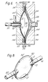
- a disposable cell mountable in a diaphragm pump as illustrated in Fig. 4 and comprising an elastically flexible wall 2 which, in Fig. 1, is seen to touch a second wall 4 which, in this embodiment, is rigid and, with its convex face, accurately fits the concave cavity surface 6 of the pump housing half 8 (Fig. 4).
- an inlet port 10 communicating via a socket 12 with a nonreturn valve that serves as inlet valve 14, and an outlet port 16 communicating via another socket 18 with a nonreturn valve serving as outlet valve 20.
- the two walls 2 and 4 are joined at the peripheral, flange-like rim 22 of the latter, which also serves for tightly mounting the cell inside the pump housing, as seen in Fig. 4 (in which, for reasons of clarity, the clamping means have been omitted).
- recesses 24 in the rigid wall 4 fanning out from a central boss as clearly seen in Fig. 4, where they are not covered by the flexible wall 2.
- the function of these recesses is to facilitate inflow and to prevent fluid from being trapped at the end of the output stroke of the flexible wall 2.
- Fig. 4 shows the disposable cell according to the invention as mounted in a standard diaphragm pump which comprises the first housing half 8, a second housing half 26, a pump diaphragm 28 and an actuator rod 30 adapted to perform a linearly reciprocating movement produced by, e.g., a solenoid, a cam drive, a piston or the like.
- a standard diaphragm pump which comprises the first housing half 8, a second housing half 26, a pump diaphragm 28 and an actuator rod 30 adapted to perform a linearly reciprocating movement produced by, e.g., a solenoid, a cam drive, a piston or the like.
- the flexible wall 2 in a manner to be discussed further below, has attached itself to the inner surface of the pump diagram 28, thus creating a working space 32 which, as can be seen, is completely isolated from all members of the pump proper.
- Seen are also narrow ducts 34 which, registering with similar ducts 36 in the housing half 26, lead to bleeder valves 38. These are nonreturn valves that permit air to exit, but prevent its return.
- the pump is actuated.
- the pump diaphragm 28 moves towards the flexible wall 2 of the cell which, initially, may be in a fairly flat, intermediate position.
- the diaphragm 28 Before the diaphragm 28 reaches the flexible wall 2, all the air in the space between wall 2 and diaphragm 28 is expelled through the ducts 34, 36 and the nonreturn, bleeder valves 38.
- the diaphragm 28 has made full contact with the flexible wall 2 and has pressed it against the rigid wall 4, the relative positions of these two walls being as shown in Fig. 1.
- the wall 2 or the diaphragm 28 For better adhesion of the flexible wall 2 of the cell to the diaphragm 28, it is possible to provide either the wall 2 or the diaphragm 28 with an adhesive layer which, after the "priming" stroke, will cause these surfaces to stick together, even if one or more bleeder valve 38 should fail in their nonreturn function.
- the adhesive used must be of the nonsetting or noncuring type, so that when the disposable cell has to be removed, say, for a change of working fluid, the flexible wall 2 is easily peeled off the diaphragm 28.
- the inlet ports 10 are arranged concentrically around the central outlet port 16.
- the inlet valve 14 can be unscrewed from the central valving stem 40.
- the bleeder ducts 36 are arranged in an annular member 42 rather than in the housing half 26.
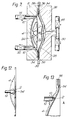
- Fig. 6 illustrates a variant of the embodiment of Fig. 5, in which there is provided a disposable cell having two flexible walls 2, 2′.
- the wall 2′ is attached to the cavity surface of the housing half 8 in the same "priming" procedure during which the wall 2 is attached to the inner surface of the pump diaphragm 28.
- grooves 44 in the diaphragm surface which lead into the bleeding ducts 34.
- Similar grooves, 44′ are provided in the cavity surface of housing half 8, which lead into bleeding ducts 34′.
- Fig. 7 illustrates a disposable cell as used in a hydraulically or pneumatically operated diaphragm pump.
- the cell is seen to consist of a flexible wall 2 and a rigid wall 4 with peripherally located ports 10 and 16 and the inlet and outlet valves 14 and 20 associated with these ports.
- the pulsating hydraulic or pneumatic working fluid 46 is controlled by valves 48 and 50.
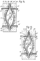
- Fig. 8 shows a disposable cell having two flexible walls 2, 2′ and peripheral, diametrically opposite inlet and outlet ports 10 and 16, the whole held together by flanges 52, 52′.
- a diaphragm pump using such a cell is shown in Fig. 9 and is similar to the embodiment of Fig. 6, except for the peripheral, diametrically opposite inlet and outlet facilities.
- Fig. 10 illustrates a disposable cell for use in a magneto-electro-mechanical diaphragm pump such as disclosed in U.S. Patent 4,498,850, represented in Figs. 14 and 15.
- the cell of which the above-mentioned pump uses two, comprises a flexible wall 2, a thin, but rigid wall 4, a peripheral inlet port 16, a peripheral outlet port 10, and the respective sockets 18 and 12.
- this pump needs no valves.
- the flange-like rim of the rigid wall 4 is provided with a trough-like recess 54, lined with part of the rim portion of the flexible wall and shown to better advantage in the enlarged detail A of Fig. 11 and the top view of Fig. 12, sectioned along the plane XII-XII of Fig. 11.
- the purpose of this recess is to facilitate escape of the air during the "priming" stage in which the flexible walls 2, 2′ of each of the disposable cells are being attached to the respective surfaces of the pump diaphragm 28 (see Fig. 4).
- Fig. 13 represents a different configuration of the detail A of Fig. 10.
- the recess 54 does not lead right to the edge of the rim, but ends somewhat below the edge. Escape of the air trapped between the flexible wall 2 and the pump diaphragm 28 (see Fig. 14) is facilitated by a duct 56 which, in the assembled pump (not shown with this embodiment), leads via an appropriately located bore in the pump housing into the atmosphere.
- Fig. 14 shows the disposable cells of Fig. 10 as mounted in the above-mentioned pump which is of the peristaltic type and the operation of which is described in the above U.S. Patent. It is seen that the flexible wall 2′ is already attached to the right-hand surface of the diaphragm 28. It is also seen that the recess 54′ is now pinched off and will remain closed even when, in continuation of the "priming" process, the upper part of the diaphragm 28 will flip over to the left, because of the pressure prevailing at the upper region near the outlet ports 10, 10′, which produces a pressure difference acting on the flexible wall 2.
- bores 36, 36′ provided in the housing halves 8, 26 and located in alignment with the recesses 54, 54′.
- Fig. 15 The fully “primed” pump is shown in Fig. 15, where also the flexible wall 2 of the left cell is seen to have become attached to the diaphragm 28.
- Fig. 16 illustrates the use of the disposable cell according to the invention in a solenoid-actuated diaphragm valve.
- the cell, mounted in the split body of the valve comprises the flexible wall 2 and the rigid wall 4, in an arrangement similar to that shown in the diaphragm pump of Fig. 4, including the air bleeding ducts 34 in the diaphragm 28, their continuation 36 in the valve body, and the bleeder valves 38.
- the actuator rod 30, the lower end of which is articulated to the diaphragm 28, is in this embodiment part of the armature of a solenoid 60 which comprises a coil 62 connectable to a power source, a guide sleeve 64 in which the rod 30 can smoothly move, and a helical spring 66 by which the valve diaphragm 28 is biased towards the closed position of the valve.
- the cell has an inlet port 10 with a slightly raised rim for increased contact pressure in the closed state of the valve, an inlet socket 12, an outlet port 16 and an outlet socket 18. Attachment of the flexible wall 2 of the surface of the diaphragm 28 is carried out in the same way as was explained in conjunction with the embodiment of Fig. 4.
- valve Operation of the valve is almost self-explanatory.
- the valve is in the "open” position, i.e., the solenoid 60 has been energized and drawn the rod 30 into its upper position inside the sleeve 64, against the restoring force of the spring 66.
- a mechanical locking feature takes over, so that the solenoid need not be kept under current to maintain the "open” state of the valve.
- a further current impulse is applied, which releases the lock and permits the spring 66 to push the rod 30 down, causing the flexible wall 2 to be pressed against, and thereby closing, the inlet port 10.
- a version of the cell in which the latter can either be stopped with the pump diaphragm 28 at the outermost position of the expulsion stroke, or in which the diaphragm 28 can be brought to this position manually, a version of the cell, mentioned in conjunction with Figs. 1-4 before, can be used that would combine the otherwise separate stages of mounting the cell and "priming" the pump in a single stage and would also obviate the need for the ducts 34,36 and the non-return bleeder valves 38.
- the flexible wall 2 rather than touching, in the unmounted state of the cell, the inside of the rigid wall 4, is fairly flat, stretched across the flange-like rim 22.
- the cell For mounting (and “priming"), the cell is introduced into the cavity of the housing half 8, and the other housing half 26, with the pump diaphragm 28 now in the aforementioned extreme, outwardly bulging position, is applied against the first half 8 prior to clamping.
- First to touch and depress the initially flat wall 2 is the central, protruding portion of the diaphragm 28, and the closer the two housing halves 8,26 approach one another, the more does this contact spread gradually outwards toward the periphery, and as the faces of the housing halves are not completely touching until the very last moment of the mounting operation, there is no problem of air being trapped between the flexible wall 2 and the diaphragm 28. There is, therefore, no need for the passages 34,36 and the bleeder valve 38. When the two halves 8,26 are tightly clamped, the flexible wall 2 will have assumed the position shown in Fig. 4.
Landscapes
- Engineering & Computer Science (AREA)
- Mechanical Engineering (AREA)
- General Engineering & Computer Science (AREA)
- External Artificial Organs (AREA)
- Reciprocating Pumps (AREA)
Claims (11)
- Einweg- bzw. Wegwerfzelle zum Einbau innerhalb einer membranbetätigten Fluidübertragungssteuervorrichtung mit Zwangsansaugung und Austreibung, die ein aus zwei im wesentlichen aneinanderliegenden Hälften (8, 26) bestehendes geteiltes Gehäuse aufweist, wobei die genannte Zelle an ihrer Peripherie zwischen eine Peripheriezone einer Hälfte (8) des genannten geteilten Gehäuses und eine Peripheriezone der genannten Membran (28) geklemmt ist, umfassend:
zwei Zellwände (2, 4), die an ihrem Umfang dauerhaft und fluiddicht miteinander verbunden sind, wobei zumindest eine der genannten Wände (2, 4) flexibel ist und die genannte zumindest eine Wand (2) so ausgebildet ist, daß sie von einer ersten Position, in der sie sich in großer Nähe zur anderen Wand (4) befindet, wobei der von den genannten beiden Wänden eingeschlossene Raum verringert wird, in zumindest eine zweite Position gebogen wird, in der zumindest einige Bereiche der genannten zumindest einen Wand (2) sich von der genannten anderen Wand wegbewegt haben, wodurch der genannte Raum zwischen den genannten beiden Wänden vergrößert wird, und
einen Einlaß (10) und einen Auslaß (16), die in zumindest einer der genannten Wände vorgesehen sind, wodurch die genannte Zelle weiterhin ein mit dem genannten Einlaß (10) in Verbindung stehendes Einlaßventil (14) und ein mit dem genannten Auslaß (16) in Verbindung stehendes Auslaßventil (20) umfaßt und die Wände (2, 4) davon im eingebauten und betriebsbereiten Zustand der genannten Einwegzelle eine undurchlässige Verkleidung einer Hälfte (8) des genannten geteilten Gehäuses einerseits und der genannten Membran (28) anderseits darstellen. - Einwegzelle nach Anspruch 1, dadurch gekennzeichnet, daß eine (4) der genannten Wände (2, 4) starr und mit einem flanschartigen Rand (22) versehen ist.
- Einwegzelle nach Anspruch 1, dadurch gekennzeichnet, daß beide der genannten Wände (2, 4) flexibel sind.
- Einwegzelle nach Anspruch 2, dadurch gekennzeichnet, daß der genannte flanschartige Rand (22) mit zumindest einer im wesentlichen radialen trogartigen Ausnehmung (54) versehen ist, die sich über die gesamte Breite des Randes (22) erstreckt.
- Einwegzelle nach Anspruch 4, dadurch gekennzeichnet, daß sich die genannte trogartige Ausnehmung (54) von der Innenkante des genannten Randes (22) zu einem Punkt unterhalb der Außenkante davon erstreckt, und die des weiteren einen Kanal (56) umfaßt, der von einem Punkt innerhalb der genannten Ausnehmung durch den genannten Rand (22) zur Außenkante davon führt.
- Einwegzelle nach Anspruch 1, dadurch gekennzeichnet, daß die Außenfläche der genannten zumindest einen flexiblen Wand (2) mit einem Haftbelag versehen ist.
- Verbesserung in einer membranbetätigten Fluidübertragungssteuervorrichtung mit Zwangsansaugung und Austreibungshub, die ein geteiltes Gehäuse aufweist, das aus zwei im wesentlichen aneinanderliegenden Hälften (8, 26) besteht, umfassend:
eine Einwegzelle zum Einbau innerhalb des genannten geteilten Gehäuses, die an ihrer Peripherie zwischen eine Peripheriezone einer Hälfte (8) des genannten geteilten Gehäuses und eine Peripheriezone der genannten Membran (28) geklemmt ist, wobei die genannte Zelle zwei Zellwände (2, 4) aufweist, die dauerhaft und fluiddicht am Umfang miteinander verbunden sind, wobei zumindest eine dieser Wände (2) flexibel ist und zumindest eine der genannten Wände mit der genannten Membran (28) verbindbar und zur Teilnahme an deren Bewegung fähig ist, wobei die genannte eine Wand (2) so ausgebildet ist, daß sie von einer ersten Position, in der sie sich in großer Nähe zur anderen Wand (4) befindet, wobei der von den genannten beiden Wänden eingeschlossene Raum verringert wird, in zumindest eine zweite Position gebogen wird, in der zumindest einige Bereiche der genannten zumindest einen Wand (2) sich von der genannten anderen Wand (4) wegbewegt haben, wodurch der genannte Raum zwischen den genannten beiden Wänden (2, 4) vergrößert wird,
einen Einlaß (10) und einen Auslaß (16), die in zumindest einer der genannten Wände vorgesehen sind, wodurch die genannte Zelle weiterhin ein mit dem genannten Einlaß (10) in Verbindung stehendes Einlaßventil (14) und ein mit dem genannten Auslaß (16) in Verbindung stehendes Auslaßventil (20) umfaßt und eine Einrichtung zum Freisetzen von zwischen zumindest der genannten verbindbaren flexiblen Wand (2) eingeschlossener Luft vorgesehen ist, wobei die genannte Einrichtung zumindest einen Bereich in der genannten Membran (28) umfaßt, der zum Durchleiten von Luft ausgebildet ist, und wobei die Wände (2, 4) davon im eingebauten und betriebsbereiten Zustand der genannten Einwegzelle eine undurchlässige Verkleidung einer Hälfte (8) des genannten geteilten Gehäuses einerseits und der genannten Membran (28) anderseits darstellen. - Fluidübertragungssteuervorrichtung nach Anspruch 7, dadurch gekennzeichnet, daß sie zumindest eine Entlüftungsleitung (34, 36) in zumindest einem Teil des genannten geteilten Gehäuses umfaßt.
- Fluidübertragungssteuervorrichtung nach Anspruch 8, dadurch gekennzeichnet, daß die genannte zumindest eine Entlüftungsleitung (34, 36) mit einem Rückschlagventil (38) ausgestattet ist, das es ermöglicht, daß eingeschlossene Luft von der genannten Entlüftungsleitung über das genannte Ventil (38) in die Atmosphäre gelangt, das aber Luft aus der Atmosphäre daran hindert, wieder in die genannte zumindest eine Entlüftungsleitung (34, 36) einzutreten.
- Fluidübertragungssteuervorrichtung nach Anspruch 7, dadurch gekennzeichnet, daß der genannte Bereich aus zumindest einer Luftleitung (44) besteht, die von zumindest einer Oberfläche der genannten Membran (28) zur genannten zumindest einen Entlüftungsleitung (36) im genannten zumindest einen Gehäuseteil (26) führt.
- Fluidübertragungssteuervorrichtung mit Zwangsansaugung und Austreibungshub, umfassend:
ein geteiltes Gehäuse, das aus zwei im wesentlichen aneinanderliegenden Hälften (8, 26) besteht;
eine Membran (28), die mit Hilfe einer Betätigungsstange (30) linear hin- und herbeweglich ist und an ihrer Peripherie zwischen Peripheriezonen der Elemente des genannten geteilten Gehäuses geklemmt eingebaut ist;
eine Einwegzelle bestehend aus zwei Zellwänden (2, 4), die dauerhaft und fluiddicht an ihrem Umfang miteinander verbunden sind, wobei die genannte Zelle an ihrer Peripherie zwischen eine Peripheriezone einer Hälfte des genannten geteilten Gehäuses und eine Peripheriezone der genannten Membran (28) geklemmt ist, wobei zumindest eine der genannten Wände (2, 4) flexibel ist und die genannte zumindest eine Wand (2) so ausgebildet ist, daß sie von einer ersten Position, in der sie sich in großer Nähe zur anderen Wand (4) befindet, wobei der von den genannten beiden Wänden eingeschlossene Raum verringert wird, in zumindest eine zweite Position gebogen wird, in der zumindest einige Bereiche der genannten zumindest einen Wand (2) sich von der genannten anderen Wand wegbewegt haben, wodurch der genannte Raum zwischen den genannten beiden Wänden vergrößert wird, und
einen Einlaß (10) und einen Auslaß (16), die in zumindest einer der genannten Wände vorgesehen sind, wodurch die genannte Zelle weiterhin ein mit dem genannten Einlaß (10) in Verbindung stehendes Einlaßventil (14) und ein mit dem genannten Auslaß (16) in Verbindung stehendes Auslaßventil (20) umfaßt und die Wände (2, 4) davon im eingebauten und betriebsbereiten Zustand der genannten Einwegzelle eine undurchlässige Verkleidung einer Hälfte (8) des genannten geteilten Gehäuses einerseits und der genannten Membran (28) anderseits darstellen.
Priority Applications (1)
| Application Number | Priority Date | Filing Date | Title |
|---|---|---|---|
| AT88303654T ATE78555T1 (de) | 1987-07-20 | 1988-04-22 | Einweg-zell-membranpumpe. |
Applications Claiming Priority (2)
| Application Number | Priority Date | Filing Date | Title |
|---|---|---|---|
| IL83259 | 1987-07-20 | ||
| IL83259A IL83259A (en) | 1987-07-20 | 1987-07-20 | Disposable cell and diaphragm pump for use of same |
Publications (3)
| Publication Number | Publication Date |
|---|---|
| EP0307069A2 EP0307069A2 (de) | 1989-03-15 |
| EP0307069A3 EP0307069A3 (en) | 1990-04-18 |
| EP0307069B1 true EP0307069B1 (de) | 1992-07-22 |
Family
ID=11057995
Family Applications (1)
| Application Number | Title | Priority Date | Filing Date |
|---|---|---|---|
| EP88303654A Expired - Lifetime EP0307069B1 (de) | 1987-07-20 | 1988-04-22 | Einweg-Zell-Membranpumpe |
Country Status (5)
| Country | Link |
|---|---|
| US (1) | US5002471A (de) |
| EP (1) | EP0307069B1 (de) |
| AT (1) | ATE78555T1 (de) |
| DE (1) | DE3872994T2 (de) |
| IL (1) | IL83259A (de) |
Cited By (1)
| Publication number | Priority date | Publication date | Assignee | Title |
|---|---|---|---|---|
| DE102014013779A1 (de) | 2014-09-17 | 2016-03-17 | Knf Flodos Ag | Membranpumpe |
Families Citing this family (100)
| Publication number | Priority date | Publication date | Assignee | Title |
|---|---|---|---|---|
| GB2226606B (en) * | 1988-12-08 | 1993-05-05 | Astra Tech Ab | Positive displacement pump |
| DK8391A (da) * | 1991-01-18 | 1992-07-19 | Uno Plast As | Sugepumpe til brug ved udsugning af legemsvaeske fra kropshulrum |
| US5262068A (en) * | 1991-05-17 | 1993-11-16 | Millipore Corporation | Integrated system for filtering and dispensing fluid having fill, dispense and bubble purge strokes |
| US5302093A (en) * | 1992-05-01 | 1994-04-12 | Mcgaw, Inc. | Disposable cassette with negative head height fluid supply and method |
| US5554013A (en) * | 1992-05-01 | 1996-09-10 | Mcgaw, Inc. | Disposable cassette with negative head height fluid supply |
| US5306257A (en) * | 1992-05-04 | 1994-04-26 | Prime Medical Products, Inc. | Drug infuser |
| JPH062664A (ja) * | 1992-06-22 | 1994-01-11 | Nippon Soken Inc | ダイアフラム式ポンプ |
| US5876190A (en) * | 1996-01-03 | 1999-03-02 | Buchi Labortechnik Ag | Vacuum membrane pump and a head portion for a vacuum membrane pump |
| US6942469B2 (en) * | 1997-06-26 | 2005-09-13 | Crystal Investments, Inc. | Solenoid cassette pump with servo controlled volume detection |
| FR2780476B1 (fr) * | 1998-06-30 | 2000-09-15 | Peugeot | Dispositif de transmission d'un volume de fluide sous pression et membrane pour un tel dispositif |
| US6877713B1 (en) | 1999-07-20 | 2005-04-12 | Deka Products Limited Partnership | Tube occluder and method for occluding collapsible tubes |
| US6497676B1 (en) | 2000-02-10 | 2002-12-24 | Baxter International | Method and apparatus for monitoring and controlling peritoneal dialysis therapy |
| US6428289B1 (en) * | 2000-12-21 | 2002-08-06 | Grigori Lishanski | Automated pump |
| ES2288887T3 (es) | 2001-01-02 | 2008-02-01 | Medela Holding Ag | Bomba de membrana. |
| US20030017056A1 (en) * | 2001-07-19 | 2003-01-23 | Baxter International Inc. | Pump having flexible liner and merchandiser having such a pump |
| US20030017066A1 (en) * | 2001-07-19 | 2003-01-23 | Baxter International Inc. | Apparatus, flexible bag and method for dispensing |
| US6905314B2 (en) | 2001-10-16 | 2005-06-14 | Baxter International Inc. | Pump having flexible liner and compounding apparatus having such a pump |
| US6769231B2 (en) | 2001-07-19 | 2004-08-03 | Baxter International, Inc. | Apparatus, method and flexible bag for use in manufacturing |
| GB2378734A (en) | 2001-08-14 | 2003-02-19 | Carmeli Adahan | Disposable pump with detachable motor |
| US7153286B2 (en) * | 2002-05-24 | 2006-12-26 | Baxter International Inc. | Automated dialysis system |
| US20030220607A1 (en) * | 2002-05-24 | 2003-11-27 | Don Busby | Peritoneal dialysis apparatus |
| US7175606B2 (en) | 2002-05-24 | 2007-02-13 | Baxter International Inc. | Disposable medical fluid unit having rigid frame |
| US6814547B2 (en) * | 2002-05-24 | 2004-11-09 | Baxter International Inc. | Medical fluid pump |
| DE10224750A1 (de) | 2002-06-04 | 2003-12-24 | Fresenius Medical Care De Gmbh | Vorrichtung zur Behandlung einer medizinischen Flüssigkeit |
| US7238164B2 (en) | 2002-07-19 | 2007-07-03 | Baxter International Inc. | Systems, methods and apparatuses for pumping cassette-based therapies |
| MXPA05000817A (es) | 2002-07-19 | 2005-04-28 | Baxter Int | Sistemas y metodos para realizar dialisis peritoneal. |
| EP1523350B1 (de) | 2002-07-19 | 2011-04-13 | Baxter International Inc. | System für die peritonealdialyse |
| US7007824B2 (en) | 2003-01-24 | 2006-03-07 | Baxter International Inc. | Liquid dispenser and flexible bag therefor |
| US20040194196A1 (en) * | 2003-04-02 | 2004-10-07 | Muderlak Kenneth J. | Apparatus and method for automatically cleaning a tank-style toilet |
| US20050011908A1 (en) * | 2003-07-16 | 2005-01-20 | Baxter International, Inc. | Dispenser and pressure/vacuum converting machine |
| US7544048B2 (en) * | 2003-09-04 | 2009-06-09 | Grigori Lishanski | Universal vibratory pump |
| JP4691503B2 (ja) | 2003-10-28 | 2011-06-01 | バクスター・インターナショナル・インコーポレイテッド | 医療用流体システムのための、改善されたプライミング、一体性および水頭高さの方法および装置 |
| US8029454B2 (en) | 2003-11-05 | 2011-10-04 | Baxter International Inc. | High convection home hemodialysis/hemofiltration and sorbent system |
| JP4279662B2 (ja) * | 2003-12-26 | 2009-06-17 | アルプス電気株式会社 | 小型ポンプ |
| US8454324B2 (en) | 2004-03-18 | 2013-06-04 | Precision Dispensing Systems Limited | Pump |
| NZ531822A (en) * | 2004-03-18 | 2007-08-31 | Prec Dispensing Systems Ltd | A membrane pump |
| JP4722654B2 (ja) * | 2004-12-20 | 2011-07-13 | ルネサスエレクトロニクス株式会社 | オシレータ及びこれを用いたチャージポンプ回路 |
| US7935074B2 (en) * | 2005-02-28 | 2011-05-03 | Fresenius Medical Care Holdings, Inc. | Cassette system for peritoneal dialysis machine |
| US8197231B2 (en) | 2005-07-13 | 2012-06-12 | Purity Solutions Llc | Diaphragm pump and related methods |
| US7539016B2 (en) * | 2005-12-30 | 2009-05-26 | Intel Corporation | Electromagnetically-actuated micropump for liquid metal alloy enclosed in cavity with flexible sidewalls |
| CN101438057A (zh) * | 2006-03-07 | 2009-05-20 | 流体公司 | 流体能量传递装置 |
| US20140199193A1 (en) | 2007-02-27 | 2014-07-17 | Deka Products Limited Partnership | Blood treatment systems and methods |
| EP2724736B1 (de) | 2006-04-14 | 2022-06-08 | DEKA Products Limited Partnership | Kassette mit eingehauster pumpe |
| US10537671B2 (en) | 2006-04-14 | 2020-01-21 | Deka Products Limited Partnership | Automated control mechanisms in a hemodialysis apparatus |
| US8870811B2 (en) * | 2006-08-31 | 2014-10-28 | Fresenius Medical Care Holdings, Inc. | Peritoneal dialysis systems and related methods |
| US8926550B2 (en) * | 2006-08-31 | 2015-01-06 | Fresenius Medical Care Holdings, Inc. | Data communication system for peritoneal dialysis machine |
| CN101711171B (zh) | 2007-02-27 | 2014-03-26 | 德卡产品有限公司 | 血液透析系统及方法 |
| US8366655B2 (en) | 2007-02-27 | 2013-02-05 | Deka Products Limited Partnership | Peritoneal dialysis sensor apparatus systems, devices and methods |
| US8409441B2 (en) | 2007-02-27 | 2013-04-02 | Deka Products Limited Partnership | Blood treatment systems and methods |
| US9028691B2 (en) | 2007-02-27 | 2015-05-12 | Deka Products Limited Partnership | Blood circuit assembly for a hemodialysis system |
| US9517295B2 (en) | 2007-02-27 | 2016-12-13 | Deka Products Limited Partnership | Blood treatment systems and methods |
| WO2008150776A2 (en) * | 2007-05-29 | 2008-12-11 | Fresenius Medical Care Holdings, Inc. | Solutions, dialysates, and related methods |
| ES2378564T3 (es) | 2007-06-21 | 2012-04-13 | Infomed Sa | Dispositivo de circulación de fluido |
| US7892197B2 (en) * | 2007-09-19 | 2011-02-22 | Fresenius Medical Care Holdings, Inc. | Automatic prime of an extracorporeal blood circuit |
| FR2921443A1 (fr) * | 2007-09-20 | 2009-03-27 | Fresenius Vial Soc Par Actions | Pompe peristaltique lineaire a doigts ainsi qu'une membrane et un doigt pour une telle pompe |
| US8863772B2 (en) * | 2008-08-27 | 2014-10-21 | Deka Products Limited Partnership | Occluder for a medical infusion system |
| US8114276B2 (en) | 2007-10-24 | 2012-02-14 | Baxter International Inc. | Personal hemodialysis system |
| US11833281B2 (en) | 2008-01-23 | 2023-12-05 | Deka Products Limited Partnership | Pump cassette and methods for use in medical treatment system using a plurality of fluid lines |
| US10201647B2 (en) | 2008-01-23 | 2019-02-12 | Deka Products Limited Partnership | Medical treatment system and methods using a plurality of fluid lines |
| EP2254616B1 (de) | 2008-01-23 | 2016-07-06 | DEKA Products Limited Partnership | Einwegflüssigkeitshandhabungs-kassette für peritonealdialyse |
| US8062513B2 (en) | 2008-07-09 | 2011-11-22 | Baxter International Inc. | Dialysis system and machine having therapy prescription recall |
| US8057679B2 (en) | 2008-07-09 | 2011-11-15 | Baxter International Inc. | Dialysis system having trending and alert generation |
| US9514283B2 (en) | 2008-07-09 | 2016-12-06 | Baxter International Inc. | Dialysis system having inventory management including online dextrose mixing |
| US9228579B2 (en) | 2008-12-19 | 2016-01-05 | Stobbe Tech A/S | Method and device for industrial biolayer cultivation |
| DE102009012633A1 (de) | 2009-03-10 | 2010-09-23 | Fresenius Medical Care Deutschland Gmbh | Vorrichtung zum Verbinden einer externen Funktionseinrichtung mit einer Anordnung, Anordnung aufweisend eine solche Vorrichtung und Verfahren zum Verbinden |
| US8192401B2 (en) * | 2009-03-20 | 2012-06-05 | Fresenius Medical Care Holdings, Inc. | Medical fluid pump systems and related components and methods |
| JP5419008B2 (ja) | 2009-04-28 | 2014-02-19 | Smc株式会社 | ポンプ装置 |
| CN102497895A (zh) | 2009-07-15 | 2012-06-13 | 弗雷塞尼斯医疗保健控股公司 | 医疗流体盒及相关系统和方法 |
| US8720913B2 (en) * | 2009-08-11 | 2014-05-13 | Fresenius Medical Care Holdings, Inc. | Portable peritoneal dialysis carts and related systems |
| US20120063923A1 (en) * | 2010-09-10 | 2012-03-15 | Ly Jeff | Positive grip fingers in a peristaltic pump |
| DE102010053973A1 (de) | 2010-12-09 | 2012-06-14 | Fresenius Medical Care Deutschland Gmbh | Medizinisches Gerät mit einer Heizung |
| EP2654825B1 (de) | 2010-12-20 | 2017-08-02 | Fresenius Medical Care Holdings, Inc. | Medizinische flüssigkeitskassetten sowie entsprechende systeme und verfahren |
| US9624915B2 (en) | 2011-03-09 | 2017-04-18 | Fresenius Medical Care Holdings, Inc. | Medical fluid delivery sets and related systems and methods |
| CN103648540B (zh) | 2011-04-21 | 2016-06-01 | 弗雷塞尼斯医疗保健控股公司 | 医疗流体泵送系统及相关装置和方法 |
| US9186449B2 (en) | 2011-11-01 | 2015-11-17 | Fresenius Medical Care Holdings, Inc. | Dialysis machine support assemblies and related systems and methods |
| US9364655B2 (en) | 2012-05-24 | 2016-06-14 | Deka Products Limited Partnership | Flexible tubing occlusion assembly |
| US9610392B2 (en) | 2012-06-08 | 2017-04-04 | Fresenius Medical Care Holdings, Inc. | Medical fluid cassettes and related systems and methods |
| US9500188B2 (en) * | 2012-06-11 | 2016-11-22 | Fresenius Medical Care Holdings, Inc. | Medical fluid cassettes and related systems and methods |
| JP6449164B2 (ja) * | 2012-11-14 | 2019-01-09 | コーニンクレッカ フィリップス エヌ ヴェKoninklijke Philips N.V. | 流体ポンプ |
| US9561323B2 (en) | 2013-03-14 | 2017-02-07 | Fresenius Medical Care Holdings, Inc. | Medical fluid cassette leak detection methods and devices |
| US9433718B2 (en) | 2013-03-15 | 2016-09-06 | Fresenius Medical Care Holdings, Inc. | Medical fluid system including radio frequency (RF) device within a magnetic assembly, and fluid cartridge body with one of multiple passageways disposed within the RF device, and specially configured cartridge gap accepting a portion of said RF device |
| US9597439B2 (en) | 2013-03-15 | 2017-03-21 | Fresenius Medical Care Holdings, Inc. | Medical fluid sensing and concentration determination using radio frequency energy and a magnetic field |
| US9566377B2 (en) | 2013-03-15 | 2017-02-14 | Fresenius Medical Care Holdings, Inc. | Medical fluid sensing and concentration determination in a fluid cartridge with multiple passageways, using a radio frequency device situated within a magnetic field |
| US9713664B2 (en) | 2013-03-15 | 2017-07-25 | Fresenius Medical Care Holdings, Inc. | Nuclear magnetic resonance module for a dialysis machine |
| US9772386B2 (en) | 2013-03-15 | 2017-09-26 | Fresenius Medical Care Holdings, Inc. | Dialysis system with sample concentration determination device using magnet and radio frequency coil assemblies |
| US10117985B2 (en) | 2013-08-21 | 2018-11-06 | Fresenius Medical Care Holdings, Inc. | Determining a volume of medical fluid pumped into or out of a medical fluid cassette |
| US20150104336A1 (en) * | 2013-10-11 | 2015-04-16 | Checkpoint Fluidic Systems International, Ltd. | Scalable Pumping Mechanism Utilizing Anti-Synchronized Poly-Diaphragm Stack |
| CN103671042A (zh) * | 2013-12-27 | 2014-03-26 | 胜瑞兰工业设备(苏州)有限公司 | 延长隔膜疲劳寿命的计量泵用双层隔膜装置 |
| US10286135B2 (en) | 2014-03-28 | 2019-05-14 | Fresenius Medical Care Holdings, Inc. | Measuring conductivity of a medical fluid |
| EP3698826A1 (de) | 2014-06-05 | 2020-08-26 | DEKA Products Limited Partnership | System zur berechnung einer änderung im flüssigkeitsvolumen in einer pumpenkammer |
| ES2987653T3 (es) | 2015-06-25 | 2024-11-15 | Gambro Lundia Ab | Sistema y método de dispositivo médico que tiene una base de datos distribuida |
| CA3056915A1 (en) * | 2016-03-18 | 2017-09-21 | Deka Products Limited Partnership | Pressure control gaskets for operating pump cassette membranes |
| DE102016216016A1 (de) * | 2016-08-25 | 2018-03-15 | Siemens Aktiengesellschaft | Herstellung eines porösen Aluminiumfilters für eine Membranpumpe |
| WO2018114346A1 (en) | 2016-12-21 | 2018-06-28 | Gambro Lundia Ab | Medical device system including information technology infrastructure having secure cluster domain supporting external domain |
| US11135345B2 (en) | 2017-05-10 | 2021-10-05 | Fresenius Medical Care Holdings, Inc. | On demand dialysate mixing using concentrates |
| US11179516B2 (en) | 2017-06-22 | 2021-11-23 | Baxter International Inc. | Systems and methods for incorporating patient pressure into medical fluid delivery |
| US10722635B2 (en) * | 2017-10-03 | 2020-07-28 | Baxter International Inc. | Modular medical fluid management assemblies and associated machines and methods |
| US10729839B2 (en) * | 2017-10-03 | 2020-08-04 | Baxter International Inc. | Modular medical fluid management assemblies, machines and methods |
| US11504458B2 (en) | 2018-10-17 | 2022-11-22 | Fresenius Medical Care Holdings, Inc. | Ultrasonic authentication for dialysis |
| CA3248081A1 (en) | 2022-04-14 | 2023-10-19 | Viking Pump, Inc. | EXPANDABLE INTERNAL LINING PUMP |
Family Cites Families (10)
| Publication number | Priority date | Publication date | Assignee | Title |
|---|---|---|---|---|
| US3039399A (en) * | 1959-12-07 | 1962-06-19 | Foregger Company Inc | Pump |
| US3496872A (en) * | 1968-05-31 | 1970-02-24 | Trico Products Corp | Rotary motor driven pump |
| US4391600A (en) * | 1979-03-09 | 1983-07-05 | Avi, Inc. | Nonpulsating IV pump and disposable pump chamber |
| US4410322A (en) * | 1979-03-09 | 1983-10-18 | Avi, Inc. | Nonpulsating TV pump and disposable pump chamber |
| US4290346A (en) * | 1979-04-30 | 1981-09-22 | Abbott Laboratories | Intravenous pump chamber |
| US4519792A (en) * | 1982-12-06 | 1985-05-28 | Abbott Laboratories | Infusion pump system |
| US4479761A (en) * | 1982-12-28 | 1984-10-30 | Baxter Travenol Laboratories, Inc. | Actuator apparatus for a prepackaged fluid processing module having pump and valve elements operable in response to externally applied pressures |
| GB8409927D0 (en) * | 1984-04-17 | 1984-05-31 | St Andrews University Of Unive | Pump |
| FR2564942B1 (fr) * | 1984-05-25 | 1987-07-10 | Clextral | Purgeur automatique pour pompe a double membrane a commande hydraulique. |
| US4781548A (en) * | 1987-04-10 | 1988-11-01 | Alderson Richard K | Infusion pump system and conduit therefor |
-
1987
- 1987-07-20 IL IL83259A patent/IL83259A/xx not_active IP Right Cessation
-
1988
- 1988-04-22 DE DE8888303654T patent/DE3872994T2/de not_active Expired - Fee Related
- 1988-04-22 AT AT88303654T patent/ATE78555T1/de not_active IP Right Cessation
- 1988-04-22 EP EP88303654A patent/EP0307069B1/de not_active Expired - Lifetime
-
1990
- 1990-02-16 US US07/481,778 patent/US5002471A/en not_active Expired - Fee Related
Cited By (3)
| Publication number | Priority date | Publication date | Assignee | Title |
|---|---|---|---|---|
| DE102014013779A1 (de) | 2014-09-17 | 2016-03-17 | Knf Flodos Ag | Membranpumpe |
| EP3001035A2 (de) | 2014-09-17 | 2016-03-30 | Knf Flodos Ag | Membranpumpe |
| US10260493B2 (en) | 2014-09-17 | 2019-04-16 | Knf Flodos Ag | Membrane pump |
Also Published As
| Publication number | Publication date |
|---|---|
| IL83259A (en) | 1992-05-25 |
| IL83259A0 (en) | 1987-12-31 |
| DE3872994T2 (de) | 1993-02-04 |
| DE3872994D1 (de) | 1992-08-27 |
| EP0307069A2 (de) | 1989-03-15 |
| US5002471A (en) | 1991-03-26 |
| EP0307069A3 (en) | 1990-04-18 |
| ATE78555T1 (de) | 1992-08-15 |
Similar Documents
| Publication | Publication Date | Title |
|---|---|---|
| EP0307069B1 (de) | Einweg-Zell-Membranpumpe | |
| US4979944A (en) | Surgical vacuum evacuation device | |
| US4655692A (en) | Ejector pump having pressure operated motive fluid valve and electromagnetic change-over valve | |
| CA2087788C (en) | Surgical cassette | |
| US4276004A (en) | Infusion pump | |
| JP2753629B2 (ja) | 単―ダイヤフラムを有するスイッチ動作を行なう小型電磁バルブ | |
| US5546997A (en) | Easily-cleaned reusable lid including an evacuating pump | |
| US5499969A (en) | Microsurgical cassette | |
| US4865521A (en) | Vacuum breaking device for ejector pump | |
| US5006104A (en) | Heart pump having contractible guide mechanism for pusher plate | |
| EP0669141B1 (de) | Kolbenpumpe und Ausatmungsventil | |
| CA2683201A1 (en) | Disposable infusion cassette with low air bubble retention and improved valves | |
| JPH0255635B2 (de) | ||
| JPS63243575A (ja) | マイクロエレクトロバルブ | |
| BRPI0806682A2 (pt) | Dispositivo ejetor com ação de ventilação | |
| HU904790D0 (en) | Low pressure recirculation valve | |
| US5626378A (en) | Self-actuated vacuum grip | |
| EP1730403B1 (de) | Membranpumpe | |
| EP1021656A1 (de) | Pneumatisches ventil-stellglied | |
| US4366834A (en) | Back-flow prevention valve | |
| US5025828A (en) | Valve assembly for a piston compressor | |
| JP3619616B2 (ja) | 薬液供給装置の駆動方法 | |
| EP0321573B1 (de) | Hin- und herbewegende schaltungsstrukttur für pumpe | |
| GB1409859A (en) | Suction and discharge apparatus intended for sucking up and discharging two fluids without mixing thereof | |
| JP2975281B2 (ja) | 電磁弁 |
Legal Events
| Date | Code | Title | Description |
|---|---|---|---|
| PUAI | Public reference made under article 153(3) epc to a published international application that has entered the european phase |
Free format text: ORIGINAL CODE: 0009012 |
|
| AK | Designated contracting states |
Kind code of ref document: A2 Designated state(s): AT BE CH DE ES FR GB GR IT LI LU NL SE |
|
| PUAL | Search report despatched |
Free format text: ORIGINAL CODE: 0009013 |
|
| AK | Designated contracting states |
Kind code of ref document: A3 Designated state(s): AT BE CH DE ES FR GB GR IT LI LU NL SE |
|
| 17P | Request for examination filed |
Effective date: 19901009 |
|
| 17Q | First examination report despatched |
Effective date: 19910513 |
|
| GRAA | (expected) grant |
Free format text: ORIGINAL CODE: 0009210 |
|
| AK | Designated contracting states |
Kind code of ref document: B1 Designated state(s): AT BE CH DE ES FR GB GR IT LI LU NL SE |
|
| PG25 | Lapsed in a contracting state [announced via postgrant information from national office to epo] |
Ref country code: IT Free format text: LAPSE BECAUSE OF FAILURE TO SUBMIT A TRANSLATION OF THE DESCRIPTION OR TO PAY THE FEE WITHIN THE PRE;WARNING: LAPSES OF ITALIAN PATENTS WITH EFFECTIVE DATE BEFORE 2007 MAY HAVE OCCURRED AT ANY TIME BEFORE 2007. THE CORRECT EFFECTIVE DATE MAY BE DIFFERENT FROM THE ONE RECORDED.SCRIBED TIME-LIMIT Effective date: 19920722 Ref country code: SE Effective date: 19920722 Ref country code: GR Free format text: LAPSE BECAUSE OF FAILURE TO SUBMIT A TRANSLATION OF THE DESCRIPTION OR TO PAY THE FEE WITHIN THE PRESCRIBED TIME-LIMIT Effective date: 19920722 Ref country code: ES Free format text: THE PATENT HAS BEEN ANNULLED BY A DECISION OF A NATIONAL AUTHORITY Effective date: 19920722 Ref country code: BE Effective date: 19920722 Ref country code: NL Effective date: 19920722 Ref country code: LI Effective date: 19920722 Ref country code: CH Effective date: 19920722 |
|
| REF | Corresponds to: |
Ref document number: 78555 Country of ref document: AT Date of ref document: 19920815 Kind code of ref document: T |
|
| REF | Corresponds to: |
Ref document number: 3872994 Country of ref document: DE Date of ref document: 19920827 |
|
| REG | Reference to a national code |
Ref country code: CH Ref legal event code: PL |
|
| ET | Fr: translation filed | ||
| NLV1 | Nl: lapsed or annulled due to failure to fulfill the requirements of art. 29p and 29m of the patents act | ||
| PG25 | Lapsed in a contracting state [announced via postgrant information from national office to epo] |
Ref country code: LU Free format text: LAPSE BECAUSE OF NON-PAYMENT OF DUE FEES Effective date: 19930430 |
|
| PLBE | No opposition filed within time limit |
Free format text: ORIGINAL CODE: 0009261 |
|
| STAA | Information on the status of an ep patent application or granted ep patent |
Free format text: STATUS: NO OPPOSITION FILED WITHIN TIME LIMIT |
|
| 26N | No opposition filed | ||
| PGFP | Annual fee paid to national office [announced via postgrant information from national office to epo] |
Ref country code: FR Payment date: 19940411 Year of fee payment: 7 |
|
| PGFP | Annual fee paid to national office [announced via postgrant information from national office to epo] |
Ref country code: GB Payment date: 19940412 Year of fee payment: 7 |
|
| PGFP | Annual fee paid to national office [announced via postgrant information from national office to epo] |
Ref country code: AT Payment date: 19940414 Year of fee payment: 7 |
|
| PGFP | Annual fee paid to national office [announced via postgrant information from national office to epo] |
Ref country code: DE Payment date: 19940426 Year of fee payment: 7 |
|
| PG25 | Lapsed in a contracting state [announced via postgrant information from national office to epo] |
Ref country code: AT Effective date: 19950422 Ref country code: GB Effective date: 19950422 |
|
| GBPC | Gb: european patent ceased through non-payment of renewal fee |
Effective date: 19950422 |
|
| PG25 | Lapsed in a contracting state [announced via postgrant information from national office to epo] |
Ref country code: FR Effective date: 19951229 |
|
| PG25 | Lapsed in a contracting state [announced via postgrant information from national office to epo] |
Ref country code: DE Effective date: 19960103 |
|
| REG | Reference to a national code |
Ref country code: FR Ref legal event code: ST |