EP0307143A2 - Méthode pour déterminer la concentration de plusieurs gaz combustibles dans un courant - Google Patents
Méthode pour déterminer la concentration de plusieurs gaz combustibles dans un courant Download PDFInfo
- Publication number
- EP0307143A2 EP0307143A2 EP88308130A EP88308130A EP0307143A2 EP 0307143 A2 EP0307143 A2 EP 0307143A2 EP 88308130 A EP88308130 A EP 88308130A EP 88308130 A EP88308130 A EP 88308130A EP 0307143 A2 EP0307143 A2 EP 0307143A2
- Authority
- EP
- European Patent Office
- Prior art keywords
- gas stream
- gas
- electrical current
- cell
- combustible
- Prior art date
- Legal status (The legal status is an assumption and is not a legal conclusion. Google has not performed a legal analysis and makes no representation as to the accuracy of the status listed.)
- Withdrawn
Links
Images
Classifications
-
- G—PHYSICS
- G01—MEASURING; TESTING
- G01N—INVESTIGATING OR ANALYSING MATERIALS BY DETERMINING THEIR CHEMICAL OR PHYSICAL PROPERTIES
- G01N27/00—Investigating or analysing materials by the use of electric, electrochemical, or magnetic means
- G01N27/26—Investigating or analysing materials by the use of electric, electrochemical, or magnetic means by investigating electrochemical variables; by using electrolysis or electrophoresis
- G01N27/403—Cells and electrode assemblies
- G01N27/404—Cells with anode, cathode and cell electrolyte on the same side of a permeable membrane which separates them from the sample fluid, e.g. Clark-type oxygen sensors
- G01N27/4045—Cells with anode, cathode and cell electrolyte on the same side of a permeable membrane which separates them from the sample fluid, e.g. Clark-type oxygen sensors for gases other than oxygen
Definitions
- the invention relates to a method for determining the concentration of a plurality of combustible gases in a gas stream.
- An electrochemical cell apparatus includes an electrochemical cell in which a cavity is formed having a diffusion limiting port forming the entrance to the cavity.
- the electrochemical cell has a process side in flow communication with a portion of the gas stream flowing into the cavity through the diffusion limiting port, and a reference side in flow communication with a reference gas.
- the process side and the reference side of the electrochemical cell are separated by an electrolyte.
- the potential difference across the electrochemical cell is adjusted to create a steady state electrical current flow whereby the flow of oxygen ions from the reference side of the electrochemical cell through the electrolyte to the process side of the electrochemical cell is equal to that required to just consume the flow of combustible gases from the gas stream through the diffusion limiting port into the cell cavity.
- a number of the following electrical current flow measurements are then obtained, wherein the number of electrical current flow measurements is equal to the number of combustible gases in the gas stream: determining the value of the steady state electrical current flowing through the electrolyte, and determining the surge of electrical current flowing through the electrolyte, over and above the steady state electrical current flow, after the flow of electrical current is interrupted and then restored, by interrupting the electri cal current flowing through the electrolyte for a time period, t, after the time period, t, restoring the flow of electrical current through the electrolyte, and measuring the surge of electrical current flowing through the electrolyte over and above the steady state electrical current flow until the electrical current flow attains its steady state value.
- the total pressure of the gases in the gas stream is determined, and the total pressure and the electrical current flow measurements are converted into a indication of the concentration of each of the combustible gases in the gas stream.
- the electrical current flow measure ments are converted into an indication of the partial pressures of the combustible gases in the gas stream, and the concentration of each of the combustible gases in the gas stream is determined by dividing the partial pressures of each of the combustible gases by the total pressure of the gas stream.
- V volume of the electrochemical cell cavity
- F Faraday's number
- R the universal gas constant
- T the absolute temperature of the gas within the cell cavity
- h Gy the number of electrons transferred in the half cell equation when combustible gas Gy is reacted with oxygen ions
- P s Gy is the partial pressure of combustible gas Gy in the gas stream
- k (2* ⁇ *R2)/[2*r*l) + R2]
- R is the radius of the electrochemical cell l is the difference between the length L and the radius R of the electrochemical cell
- r the radius of the diffusion limiting port
- D Gy is the diff
- the present invention enables one to determine the concentration of each of the combustible gases in a gas stream.
- the subject invention is a method for determining the concentration of each of a plurality of combustible gases in a gas stream.
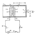
- an electrochemical cell 1 typical of the type that can be used in the method of the subject invention, is schematically illustrated in Figure 1.
- Such an electrochemical cell 1 includes a cavity 3, with a diffusion limiting port 5 forming the entrance to the cavity 3.
- the size of the diffusion limiting port 5 is determined according to engineering principles such that the countercurrent diffusion flow of the various combustible gases, typically hydrogen, carbon monoxide and methane, and of the corresponding combustion products, water vapor and carbon dioxide, can be balanced by the stoichiometric oxygen ion flow through the solid electrolyte of the electrochemical cell 1.
- the cavity 3 further includes a process side 7 in flow communication with the portion of the gas stream flowing into the cavity 3 through the diffusion limiting port 5 and a reference side 9 in flow communication with a reference gas.
- the electrochemical cell 1 is preferably formed of a ceramic material and an electrolyte 11, such as an oxide, that is capable of conducting oxygen ions.
- Suitable oxides include zirconium oxide, cesium oxide and thorium oxide.
- An electrode 13 is attached to the process side 7 of the cell 1 and an electrode 15 is attached to the reference side 9 of the cell 1.
- the electrical circuit 21 further includes a variable resistor 23, ammeter 25 and switch 27.
- the electrochemical cell 1 can be used to measure the concentration of combustible gases in a gas stream. Under reducing conditions in the gas stream, when the switch 27 is closed, the combustible gases diffuse from the gas stream through the diffusion limiting port 5 into the cavity 3 of the electrochemical cell 1. Concurrently, the difference in the partial pressure of oxygen between the reference gas and the gas stream causes oxygen ions to diffuse from the reference gas through the electrolyte 11 toward the lower oxygen partial pressure of the gas stream in the cavity 3 of the electrochemical cell 1 and react with the combustible gases in the cell cavity to form the combustion products, water and carbon dioxide. A potential difference is created between the electrodes 13 and 15 which causes an electrical current to flow between the electrodes 13 and 15, the strength of which can be measured by the ammeter 25.
- An external voltage based on the current carrying capacity of the reference electrode 15 of the electrochemical cell 1 and the concentration range of the gases to be analyzed, is applied to the electrodes 13 and 15 initially to excite the cell 1.
- the anode electrode is the process side electrode 13 and the cathode electrode is the reference side electrode 15.
- the reaction at the cathode is: O2 + 4e ⁇ ⁇ 202 ⁇ and the reactions at the anode are, if the combustible gases include hydrogen and carbon monoxide: CO + O ⁇ ⁇ 2e ⁇ + CO2, and H2 + O ⁇ ⁇ 2e ⁇ + H2O.
- the combustion products diffuse back to the gas stream from the cavity 3 through the diffusion limiting port 5.
- a number of the following electrical current flow measurements are obtained, wherein the number of electrical current flow measurements is equal to the number of combustible gases in the gas stream.
- One such electrical current flow measurement is the value of the steady state electrical current flowing through the electrolyte 11.
- Other such electrical current flow measurements are the surge of electrical current flowing through the electrolyte 11, over and above the steady state electrical current flow, after the flow of electrical current is interrupted and then restored, until the time at which the electrical current flow attains its steady state value.
- the switch 27 is closed and the current flowing through the electrolyte 11 is adjusted, as for example through the variable resistor 23, so that the potential difference across the electrochemical cell 1 corresponds to that developed when the diffusion of oxygen ions from the reference side 9 of the electrochemical cell 1 through the electrolyte 11 to the process side 7 of the electrochemical cell 1 and into the cell cavity 3 equals the diffusion rate of the combustible gases from the combustible gas stream through the diffusion limiting port 5 into the cavity 3 of the electrochemical cell 1.
- the ammeter 25 registers the strength of the resulting steady state electrical current, i.
- the switch 27 In order to measure a current surge, Q, the switch 27 is opened for a preselected period of time, t, thus interrupting the flow of electrical current through the electrolyte 11. The switch 27 is then closed and the resulting surge of electrical current, Q, over and above the steady state electrical current, is recorded from the ammeter 25 as a function of the time after the restoration of electrical current flow until the electrical current flow attains its steady state value.
- the total pressure of the gases in the gas stream is measured, and the total pressure of the gas stream, and the electrical current flow measurements, are converted into an indication of the concentration of each of the combustible gases in the gas stream.
- the electrical current flow measurements are converted into an indication of the partial pressures of the combustible gases in the gas stream, and the concentration of each of the combustible gases in the gas stream is determined by dividing the partial pressures of each of the combustible gases by the total pressure of the gas stream.
- the electrical current flow measurements can be converted into an indication of the partial pressures of the combustible gases in the gas stream from relationships described hereinbelow:
- the current flow, i represents both the oxygen ion flow through the electrolyte 11 and the flow of combustible gases through the diffusion limiting port 5 into the cell cavity 3 as follows: h O2 is 4, the number of electrons transferred in the half cell equation: O2 + 4e ⁇ ⁇ 20 ⁇ d O2 is the diffusion rate of oxygen ions through the electrolyte 11; F is Faraday's number; G1 through Gn are the n combustible gases in the gas stream; h Gx is the number of electrons transferred in the half cell equation: Gx + O ⁇ ⁇ ; and d Gx is the diffusion rate of the gas Gx into the cell cavity 3.
- Equation 2B F * [(2 * d H2) + (2 * d CO)] (equation 2C)
- d Gx of equation 3 can be substituted for d Gx of equation 2 as follows:
- Equation 4A F*k*A * [(2* D H2* P s H2) + (8* D CH4* P s CH4) + (2* D CO* P s CO)]
- the oxygen ion flow from the reference side 9 to the process side 7 of the electrochemical cell 1 will be interrupted, and combustible gases flowing into the cell cavity 3 will accumulate within the cell cavity 3 because of the lack of available oxygen ions with which to react.
- a surge of oxygen ions will flow from the reference side 9 of the electrochemical cell 1 through the electrolyte 11 to the process side 7 of the electrochemical cell 1 as the oxygen ions react with the combustible gases that have accumulated within the cell cavity 3 during the time that the electrical current, and oxygen ion flow through the electrolyte 11, was interrupted.
- a surge of electrical current, in excess of the steady state current, will occur as the oxygen ions flow through the electrolyte 11 to react with the accumulated combustible gases within the cell cavity 3.
- the integral of the electrical current surge over the time period from electrical current flow restoration until the electrical current flow attains its steady state value can be represented by the relationship: idt, hereinater represented as Q, is the integral of the electrical current surge over the time period from electrical current flow restoration until the electrical current flow attains its steady state value; V is the volume of the cavity 3 of the electrochemical cell 1; R is the universal gas constant; T is the absolute temperature of the gas within the cell cavity 3; and P c Gx is the partial pressure of the gas Gx in the cell cavity 3.
- equation 5 [(V*F)/(R*T)] * [(2*P c H2) + (8*P c CH4) + (2*P c CO)] (equation 5A)
- Equation 5 [(V*F)/(R*T)] * [(2* P c H2) + (2* P c CO)] (equation 5B)
- the concentration of the combustible gases in the gas stream can be determined as follows:
- equation 8A can be substituted for P c of equation 5, and the surge of electrical current measured after the electrical current flow is interrupted and then restored, until the electrical current flow attains its steady state value, is related to the partial pressures of the gases in the gas stream as follows:
- h Gx* P s Gx from equation 6 is used to represent those gases Gx that have reached equilibrium between the gas stream and the cell cavity 3
- h Gx* P s Gx* (1 - e (-k*D Gx*A*t) ) from equation 9 is used to represent those gases Gx which have not reached equilibrium between the gas stream and the cell cavity 3.
- i (F*k*A) * [(h G1* D G1* P s G1) + ...
- Equations 4A and 7A can be simplified to the following equations and solved for the two unknowns, namely: (1) P s H2 and (2) P s CO.
- P s H2 [[i/(2*F*k*A)] - [(D CO*Q*R*T)/(2*F*V)]]/(D H2 -D CO)
- P s CO [(Q*R*T)/(2*V*F)] - [[(i/(2*F*k*A)) -[(D CO*Q*R*T)/(2*F*V)]]/(D H2 - D CO)] (equation 11)
- the molar concentration of hydrogen and carbon monoxide in the gas stream can then be calculated by dividing their respective partial pressures, P s H2 and P s CO, by the total pressure of the gas stream.
- the concentration of those gases in the gas stream can be determined by making any three of the following five types of measurements: the steady state electrical current, i; and surge of electrical current, Q, after a time period of electrical current interruption t1, that is not sufficient for any of the gases to reach equilibrium between the gas stream and the cell cavity 3; t2, that is sufficient for hydrogen only to reach equilibrium between the gas stream and the cell cavity 3; t3, that is sufficient for hydrogen and methane, but not carbon monoxide, to reach equilibrium between the gas stream and the cell cavity 3; and t4, sufficient for the three gases to reach equilibrium between the gas stream and the cell cavity 3.
- the steady state electrical current, i and surge of electrical current, Q, after a time period of electrical current interruption t1
- t2 that is sufficient for hydrogen only to reach equilibrium between the gas stream and the cell cavity 3
- t3 that is sufficient for hydrogen and methane, but not carbon monoxide, to reach equilibrium between the gas stream and the cell cavity 3
- t4 sufficient for the three gases to reach equilibrium between the gas
- the method of the invention enables one to determine the concentration of each of the combustible gases in a gas stream.
Landscapes
- Chemical & Material Sciences (AREA)
- Life Sciences & Earth Sciences (AREA)
- Health & Medical Sciences (AREA)
- Physics & Mathematics (AREA)
- Chemical Kinetics & Catalysis (AREA)
- Electrochemistry (AREA)
- Molecular Biology (AREA)
- Analytical Chemistry (AREA)
- Biochemistry (AREA)
- General Health & Medical Sciences (AREA)
- General Physics & Mathematics (AREA)
- Immunology (AREA)
- Pathology (AREA)
- Investigating Or Analyzing Materials By The Use Of Electric Means (AREA)
- Measuring Oxygen Concentration In Cells (AREA)
Applications Claiming Priority (2)
| Application Number | Priority Date | Filing Date | Title |
|---|---|---|---|
| US07/095,382 US5007988A (en) | 1987-09-08 | 1987-09-08 | Method for determining the concentration of a plurality of combustible gases in a stream |
| US95382 | 1987-09-08 |
Publications (2)
| Publication Number | Publication Date |
|---|---|
| EP0307143A2 true EP0307143A2 (fr) | 1989-03-15 |
| EP0307143A3 EP0307143A3 (fr) | 1990-04-25 |
Family
ID=22251708
Family Applications (1)
| Application Number | Title | Priority Date | Filing Date |
|---|---|---|---|
| EP88308130A Withdrawn EP0307143A3 (fr) | 1987-09-08 | 1988-09-01 | Méthode pour déterminer la concentration de plusieurs gaz combustibles dans un courant |
Country Status (3)
| Country | Link |
|---|---|
| US (1) | US5007988A (fr) |
| EP (1) | EP0307143A3 (fr) |
| JP (1) | JPH0198956A (fr) |
Cited By (1)
| Publication number | Priority date | Publication date | Assignee | Title |
|---|---|---|---|---|
| EP1178188A3 (fr) * | 2000-08-02 | 2003-10-01 | Ford Global Technologies, Inc. | Procédé et dispositif pour la surveillance directe du rendement d'un catalyseur de conditionnement |
Families Citing this family (7)
| Publication number | Priority date | Publication date | Assignee | Title |
|---|---|---|---|---|
| US5250169A (en) * | 1991-06-07 | 1993-10-05 | Ford Motor Company | Apparatus for sensing hydrocarbons and carbon monoxide |
| US5373724A (en) * | 1992-06-02 | 1994-12-20 | Trw Inc. | Method of sensing a gas concentration |
| US5596134A (en) * | 1995-04-10 | 1997-01-21 | Defense Research Technologies, Inc. | Continuous oxygen content monitor |
| DE10014564A1 (de) * | 2000-03-23 | 2001-09-27 | Opel Adam Ag | Kraftstoffzumess-System für eine Brennkraftmaschine |
| DE10048240B4 (de) * | 2000-09-29 | 2007-02-08 | Robert Bosch Gmbh | Gassensorelement und Verfahren zur Bestimmung der Konzentration einer Gaskomponente in einem Gasgemisch |
| US20060231422A1 (en) * | 2005-04-14 | 2006-10-19 | Honeywell International Inc. | Switched gas sensor |
| US12247943B2 (en) * | 2020-12-18 | 2025-03-11 | Aeroqual Ltd. | Method to reduce unwanted signals on amperometric sensor response |
Family Cites Families (19)
| Publication number | Priority date | Publication date | Assignee | Title |
|---|---|---|---|---|
| US3315271A (en) * | 1964-04-16 | 1967-04-18 | Beckman Instruments Inc | Cell for dissolved oxidant analysis |
| NL7105976A (fr) * | 1971-04-30 | 1972-11-01 | ||
| US3865707A (en) * | 1972-12-27 | 1975-02-11 | Donald A Sayles | Combustible mixture analyzer |
| NL7309537A (nl) * | 1973-07-09 | 1975-01-13 | Philips Nv | Gasanalyse-apparaat. |
| US4158166A (en) * | 1976-11-24 | 1979-06-12 | Westinghouse Electric Corp. | Combustibles analyzer |
| US4057478A (en) * | 1976-02-05 | 1977-11-08 | The United States Of America As Represented By The Secretary Of The Interior | Electrochemical gas monitor |
| US4128458A (en) * | 1977-10-25 | 1978-12-05 | Obiaya Joseph O | Combustible element and oxygen concentration sensor |
| US4269684A (en) * | 1979-10-01 | 1981-05-26 | Cordis Corporation | Apparatus for oxygen partial pressure measurement |
| US4663017A (en) * | 1981-03-02 | 1987-05-05 | The Babcock & Wilcox Company | Combustibles sensor |
| US4380400A (en) * | 1981-03-17 | 1983-04-19 | Honeywell Inc. | Combustible gas analyzer |
| AU561654B2 (en) * | 1981-08-21 | 1987-05-14 | Rosemount Analytical Inc | Solid electrolyte gas sensor |
| JPS58118956A (ja) * | 1982-01-11 | 1983-07-15 | Hitachi Ltd | ガス検出方法とその装置 |
| US4508598A (en) * | 1982-05-11 | 1985-04-02 | Giner, Inc. | Gas sensor and method of using same |
| CH659327A5 (en) * | 1982-11-23 | 1987-01-15 | Inst Elektrokhimii Akademii Na | Method and apparatus for determining the organic carbon content of water or of an aqueous solution |
| JPS59217151A (ja) * | 1983-05-26 | 1984-12-07 | Toyota Central Res & Dev Lab Inc | 酸素イオン導電性固体電解質を用いた限界電流式酸素センサによる複数のガス成分濃度の検出装置 |
| US4547281A (en) * | 1983-11-21 | 1985-10-15 | Gte Laboratories Incorporated | Gas analysis apparatus |
| NL8304182A (nl) * | 1983-12-06 | 1985-07-01 | Philips Nv | Gasanalyse-apparaat. |
| US4496433A (en) * | 1983-12-28 | 1985-01-29 | The Foxboro Company | Apparatus and method for determining the amount of a sample gas component |
| US4735691A (en) * | 1985-12-23 | 1988-04-05 | Allied Corporation | Method for operating electrochemical detector cell |
-
1987
- 1987-09-08 US US07/095,382 patent/US5007988A/en not_active Expired - Fee Related
-
1988
- 1988-09-01 EP EP88308130A patent/EP0307143A3/fr not_active Withdrawn
- 1988-09-08 JP JP63225483A patent/JPH0198956A/ja active Pending
Cited By (1)
| Publication number | Priority date | Publication date | Assignee | Title |
|---|---|---|---|---|
| EP1178188A3 (fr) * | 2000-08-02 | 2003-10-01 | Ford Global Technologies, Inc. | Procédé et dispositif pour la surveillance directe du rendement d'un catalyseur de conditionnement |
Also Published As
| Publication number | Publication date |
|---|---|
| US5007988A (en) | 1991-04-16 |
| JPH0198956A (ja) | 1989-04-17 |
| EP0307143A3 (fr) | 1990-04-25 |
Similar Documents
| Publication | Publication Date | Title |
|---|---|---|
| US3514377A (en) | Measurement of oxygen-containing gas compositions and apparatus therefor | |
| US3907657A (en) | Gas analysis apparatus | |
| US4158166A (en) | Combustibles analyzer | |
| US3860498A (en) | Method of measuring O{HD 2 {B and O{HD 2 {B containing constituents | |
| GB1393396A (en) | Method and apparatus for measuring the combustibles and oxygen constituents of a gas | |
| US4218297A (en) | Electrochemical gauge for oxygen having an internal reference and solid electrolyte | |
| EP0307143A2 (fr) | Méthode pour déterminer la concentration de plusieurs gaz combustibles dans un courant | |
| US4057478A (en) | Electrochemical gas monitor | |
| Millot et al. | A new method for the study of chemical diffusion in oxides with application to cerium oxide CeO2− x | |
| US2861926A (en) | Electrochemical method and apparatus for gas detection | |
| US5080765A (en) | Method for determining identification and concentration of an atmospheric component | |
| US3837808A (en) | Method of analyzing oxygen | |
| US5635627A (en) | Carbon monoxide sensor having mercury doped electrodes | |
| EP0993607B1 (fr) | Dispositif et procede permettant de mesurer la composition de gaz grace a des electrolytes a conduction ionique | |
| US3843489A (en) | Method of determining surface area and meter therefor | |
| Logothetis et al. | Chemical and physical sensors based on oxygen pumping with solid-state electrochemical cells | |
| CA1114018A (fr) | Methode de detection de l'encrassement d'une pile electrochimique a membrane | |
| RU2151434C1 (ru) | Анализатор водорода в топливных таблетках из двуокиси урана | |
| Gessner et al. | Multiple Charge‐Transfer Reactions in Zirconia Electrolytic Cells: NO x Reduction on Platinum | |
| GB1604445A (en) | Device for monitoring a component in a fluid mixture | |
| SU1749816A1 (ru) | Твердоэлектролитный датчик окиси углерода | |
| RU2053506C1 (ru) | Твердоэлектролитный датчик для анализа газов | |
| SU1492263A1 (ru) | Устройство дл измерени концентрации компонентов газовой смеси | |
| JP3763430B2 (ja) | 被検ガス中のNOx濃度測定方法及び装置 | |
| Dudney et al. | Galvanic cell measurements with stabilized zirconia and platinum probes |
Legal Events
| Date | Code | Title | Description |
|---|---|---|---|
| PUAI | Public reference made under article 153(3) epc to a published international application that has entered the european phase |
Free format text: ORIGINAL CODE: 0009012 |
|
| AK | Designated contracting states |
Kind code of ref document: A2 Designated state(s): BE CH FR GB IT LI |
|
| PUAL | Search report despatched |
Free format text: ORIGINAL CODE: 0009013 |
|
| AK | Designated contracting states |
Kind code of ref document: A3 Designated state(s): BE CH FR GB IT LI |
|
| 17P | Request for examination filed |
Effective date: 19901017 |
|
| STAA | Information on the status of an ep patent application or granted ep patent |
Free format text: STATUS: THE APPLICATION HAS BEEN WITHDRAWN |
|
| 18W | Application withdrawn |
Withdrawal date: 19920623 |