EP0307367B1 - Seringue hypodermique autoblocante à usage unique, avec capuchon de protection de l'aiguille - Google Patents
Seringue hypodermique autoblocante à usage unique, avec capuchon de protection de l'aiguille Download PDFInfo
- Publication number
- EP0307367B1 EP0307367B1 EP88830315A EP88830315A EP0307367B1 EP 0307367 B1 EP0307367 B1 EP 0307367B1 EP 88830315 A EP88830315 A EP 88830315A EP 88830315 A EP88830315 A EP 88830315A EP 0307367 B1 EP0307367 B1 EP 0307367B1
- Authority
- EP
- European Patent Office
- Prior art keywords
- syringe
- cap
- plunger
- needle
- frusto
- Prior art date
- Legal status (The legal status is an assumption and is not a legal conclusion. Google has not performed a legal analysis and makes no representation as to the accuracy of the status listed.)
- Expired
Links
- 239000007788 liquid Substances 0.000 claims description 28
- 210000002105 tongue Anatomy 0.000 claims description 25
- 238000002347 injection Methods 0.000 claims description 14
- 239000007924 injection Substances 0.000 claims description 14
- 230000000903 blocking effect Effects 0.000 claims description 6
- 238000003780 insertion Methods 0.000 claims description 3
- 239000012780 transparent material Substances 0.000 claims description 3
- 230000000694 effects Effects 0.000 claims 1
- 239000003814 drug Substances 0.000 description 7
- 229940079593 drug Drugs 0.000 description 4
- 208000015181 infectious disease Diseases 0.000 description 3
- 208000030507 AIDS Diseases 0.000 description 2
- 238000000605 extraction Methods 0.000 description 2
- 238000005452 bending Methods 0.000 description 1
- 208000006454 hepatitis Diseases 0.000 description 1
- 231100000283 hepatitis Toxicity 0.000 description 1
- 230000037431 insertion Effects 0.000 description 1
- 239000000463 material Substances 0.000 description 1
- 239000000126 substance Substances 0.000 description 1
- 231100000419 toxicity Toxicity 0.000 description 1
- 230000001988 toxicity Effects 0.000 description 1
- 230000003612 virological effect Effects 0.000 description 1
- 230000002747 voluntary effect Effects 0.000 description 1
Images

Classifications
-
- A—HUMAN NECESSITIES
- A61—MEDICAL OR VETERINARY SCIENCE; HYGIENE
- A61M—DEVICES FOR INTRODUCING MEDIA INTO, OR ONTO, THE BODY; DEVICES FOR TRANSDUCING BODY MEDIA OR FOR TAKING MEDIA FROM THE BODY; DEVICES FOR PRODUCING OR ENDING SLEEP OR STUPOR
- A61M5/00—Devices for bringing media into the body in a subcutaneous, intra-vascular or intramuscular way; Accessories therefor, e.g. filling or cleaning devices, arm-rests
- A61M5/50—Devices for bringing media into the body in a subcutaneous, intra-vascular or intramuscular way; Accessories therefor, e.g. filling or cleaning devices, arm-rests having means for preventing re-use, or for indicating if defective, used, tampered with or unsterile
- A61M5/5013—Means for blocking the piston or the fluid passageway to prevent illegal refilling of a syringe
-
- A—HUMAN NECESSITIES
- A61—MEDICAL OR VETERINARY SCIENCE; HYGIENE
- A61M—DEVICES FOR INTRODUCING MEDIA INTO, OR ONTO, THE BODY; DEVICES FOR TRANSDUCING BODY MEDIA OR FOR TAKING MEDIA FROM THE BODY; DEVICES FOR PRODUCING OR ENDING SLEEP OR STUPOR
- A61M5/00—Devices for bringing media into the body in a subcutaneous, intra-vascular or intramuscular way; Accessories therefor, e.g. filling or cleaning devices, arm-rests
- A61M5/178—Syringes
- A61M5/31—Details
- A61M5/32—Needles; Details of needles pertaining to their connection with syringe or hub; Accessories for bringing the needle into, or holding the needle on, the body; Devices for protection of needles
- A61M5/3205—Apparatus for removing or disposing of used needles or syringes, e.g. containers; Means for protection against accidental injuries from used needles
- A61M5/321—Means for protection against accidental injuries by used needles
- A61M5/3243—Means for protection against accidental injuries by used needles being axially-extensible, e.g. protective sleeves coaxially slidable on the syringe barrel
- A61M5/326—Fully automatic sleeve extension, i.e. in which triggering of the sleeve does not require a deliberate action by the user
-
- A—HUMAN NECESSITIES
- A61—MEDICAL OR VETERINARY SCIENCE; HYGIENE
- A61M—DEVICES FOR INTRODUCING MEDIA INTO, OR ONTO, THE BODY; DEVICES FOR TRANSDUCING BODY MEDIA OR FOR TAKING MEDIA FROM THE BODY; DEVICES FOR PRODUCING OR ENDING SLEEP OR STUPOR
- A61M5/00—Devices for bringing media into the body in a subcutaneous, intra-vascular or intramuscular way; Accessories therefor, e.g. filling or cleaning devices, arm-rests
- A61M5/178—Syringes
- A61M5/31—Details
- A61M5/32—Needles; Details of needles pertaining to their connection with syringe or hub; Accessories for bringing the needle into, or holding the needle on, the body; Devices for protection of needles
- A61M5/3205—Apparatus for removing or disposing of used needles or syringes, e.g. containers; Means for protection against accidental injuries from used needles
- A61M5/321—Means for protection against accidental injuries by used needles
- A61M5/3243—Means for protection against accidental injuries by used needles being axially-extensible, e.g. protective sleeves coaxially slidable on the syringe barrel
- A61M5/3245—Constructional features thereof, e.g. to improve manipulation or functioning
- A61M2005/3247—Means to impede repositioning of protection sleeve from needle covering to needle uncovering position
-
- A—HUMAN NECESSITIES
- A61—MEDICAL OR VETERINARY SCIENCE; HYGIENE
- A61M—DEVICES FOR INTRODUCING MEDIA INTO, OR ONTO, THE BODY; DEVICES FOR TRANSDUCING BODY MEDIA OR FOR TAKING MEDIA FROM THE BODY; DEVICES FOR PRODUCING OR ENDING SLEEP OR STUPOR
- A61M5/00—Devices for bringing media into the body in a subcutaneous, intra-vascular or intramuscular way; Accessories therefor, e.g. filling or cleaning devices, arm-rests
- A61M5/178—Syringes
- A61M5/31—Details
- A61M5/32—Needles; Details of needles pertaining to their connection with syringe or hub; Accessories for bringing the needle into, or holding the needle on, the body; Devices for protection of needles
- A61M5/3205—Apparatus for removing or disposing of used needles or syringes, e.g. containers; Means for protection against accidental injuries from used needles
- A61M5/321—Means for protection against accidental injuries by used needles
- A61M5/3243—Means for protection against accidental injuries by used needles being axially-extensible, e.g. protective sleeves coaxially slidable on the syringe barrel
- A61M5/326—Fully automatic sleeve extension, i.e. in which triggering of the sleeve does not require a deliberate action by the user
- A61M2005/3261—Fully automatic sleeve extension, i.e. in which triggering of the sleeve does not require a deliberate action by the user triggered by radial deflection of the anchoring parts between sleeve and syringe barrel, e.g. spreading of sleeve retaining hooks having slanted surfaces by engagement with conically shaped collet of the piston rod during the last portion of the injection stroke of the plunger
- A61M2005/3264—Trigger provided at the proximal end, i.e. syringe end opposite to needle mounting end
-
- A—HUMAN NECESSITIES
- A61—MEDICAL OR VETERINARY SCIENCE; HYGIENE
- A61M—DEVICES FOR INTRODUCING MEDIA INTO, OR ONTO, THE BODY; DEVICES FOR TRANSDUCING BODY MEDIA OR FOR TAKING MEDIA FROM THE BODY; DEVICES FOR PRODUCING OR ENDING SLEEP OR STUPOR
- A61M5/00—Devices for bringing media into the body in a subcutaneous, intra-vascular or intramuscular way; Accessories therefor, e.g. filling or cleaning devices, arm-rests
- A61M5/50—Devices for bringing media into the body in a subcutaneous, intra-vascular or intramuscular way; Accessories therefor, e.g. filling or cleaning devices, arm-rests having means for preventing re-use, or for indicating if defective, used, tampered with or unsterile
- A61M5/5013—Means for blocking the piston or the fluid passageway to prevent illegal refilling of a syringe
- A61M5/502—Means for blocking the piston or the fluid passageway to prevent illegal refilling of a syringe for blocking the piston
- A61M2005/5033—Means for blocking the piston or the fluid passageway to prevent illegal refilling of a syringe for blocking the piston by use of an intermediate blocking member positioned between the syringe barrel and the piston rod to prevent retraction of the latter, e.g. toothed clip placed on the piston rod
-
- A—HUMAN NECESSITIES
- A61—MEDICAL OR VETERINARY SCIENCE; HYGIENE
- A61M—DEVICES FOR INTRODUCING MEDIA INTO, OR ONTO, THE BODY; DEVICES FOR TRANSDUCING BODY MEDIA OR FOR TAKING MEDIA FROM THE BODY; DEVICES FOR PRODUCING OR ENDING SLEEP OR STUPOR
- A61M5/00—Devices for bringing media into the body in a subcutaneous, intra-vascular or intramuscular way; Accessories therefor, e.g. filling or cleaning devices, arm-rests
- A61M5/50—Devices for bringing media into the body in a subcutaneous, intra-vascular or intramuscular way; Accessories therefor, e.g. filling or cleaning devices, arm-rests having means for preventing re-use, or for indicating if defective, used, tampered with or unsterile
- A61M5/5013—Means for blocking the piston or the fluid passageway to prevent illegal refilling of a syringe
- A61M5/502—Means for blocking the piston or the fluid passageway to prevent illegal refilling of a syringe for blocking the piston
Definitions
- This invention relates to a self-blocking hypodermic syringe for once-only use, which cannot be reused after it has been once used, and is provided with a needle protection cap which is automatically transferred into its protection position after use.
- medicaments are frequently administered to the patient hypodermically by means of a needle and syringe.
- sterile syringes for once-only use are usually employed, these being packaged in sealed containers to be opened at the moment of use.
- syringes are also used by drug addicts for drug injection, and with this category of person a considerable increase has been noted in the spread of viral illnesses, such as type B hepatitis and acquired immunodeficiency syndrome (AIDS), the cause of which is the contagion transmitted by the use of the same syringe by more than one person, who ignore the rule which prescribes its once-only use.
- viral illnesses such as type B hepatitis and acquired immunodeficiency syndrome (AIDS)
- AIDS acquired immunodeficiency syndrome
- Certain syringes comprise means for controlling the plunger stroke within the cylindrical body for various reasons.
- GB-A-551 545 discloses a syringe comprising means for delaying or braking the plunger stroke within the cylindrical body and for enabling the user to determine the quantity of injected liquid by feel.
- DE-A-3 107 414 discloses blocking means for preventing the extraction of a plunger from the cylindrical body in order to avoid contaminating the space which is to contain the liquid to be injected
- US-A-1 434 381 discloses a syringe provided with elastic braking or delay means to prevent accidental introduction of air into the liquid contained in the syringe or accidental leakage of this liquid, or again accidental escape of the plunger from the cylindrical body.
- none of the known syringes comprises means for preventing the re-use of a once-only usable syringe or for preventing accidental pricking after the syringe has been used.
- the problem therefore arises of preventing the spread of contagion by making it impossible to use the same syringe more than once, independently of the desire or negligence of the user, and of isolating the needle after the syringe has been used so that the needle is made safe.
- a self-blocking hypodermic syringe for once-only use comprising a cylindrical body which at its front end carries means for connection to a hypodermic needle and is open at its opposite end and contains a plunger which slides in a fluid-tight manner and is provided with a gripping rod, characterised by the features as specified in the second part of claim 1.
- the means for blocking the plunger intake stroke consist of a split-ring which before the syringe is initially used embraces the minor diameter region of a frusto-conical portion of the rod, which converges in the direction in which the plunger is driven for injection.
- the minor diameter region of said frusto-conical portion has a diameter less than the rod diameter and the major diameter region has a diameter substantially equal to or slightly less than the inner diameter of the cylindrical body.
- the syringe cylindrical body comprises an annular bulge which is able to receive the split-ring when this is drawn in front of it during the initial liquid intake stage, said bulge having an inner diameter greater than the diameter of the major diameter region of the frusto-conical portion plus the thickness of the split-ring and being positioned at a distance from that end of the cylindrical body carrying the needle which exceeds the distance between the front end of the plunger and the rear surface of its frusto-conical portion.
- the split-ring When in its undeformed state, the split-ring has an inner diameter less than the maximum diameter of the frusto-conical portion and an outer diameter greater than the inner diameter of the cylindrical body, and is elastically deformable to widen out into the bulge under the action of the frusto-conical surface as the plunger is driven in.
- the split-ring Before the syringe is initially used, the split-ring is in a position forward of the bulge in the cylindrical body, and is in its elastically deformed contracted state.
- the distance between the split-ring when in its initial position, i.e. embracing the minor diameter region of the frusto-conical portion, and the bulge in the cylindrical body is less than the stroke of the plunger which corresponds to the minimum scheduled liquid dosage for which the syringe can be used.
- the syringe of the invention also comprises a slidable cap coaxial to the syringe body and covering the body itself, and being provided at its front with an exit hole for the needle and further having members for its fastening to the syringe body, and elastic thrust means, said cap when in its retracted position leaving the needle exposed and when in its advanced position covering the needle, the fastening members being moved into their release position by release means associated with the first forward movement of the plunger.
- the cap fastening members consist of elastic tongues provided in the rear part of the cap and having their ends turned inwards to form a hook so that when the cap is in its retracted position they become inserted into corresponding slots in the syringe body to axially lock the cap
- the release means consisting of an elastic element which is provided within the syringe in a position corresponding to the slots in the syringe body which house the hook-shaped ends of the cap tongues and is arranged to be radially deformed by the forward stroke of the plunger during the first injection, so urging the hook-shaped ends out of the relative slots.
- the syringe body also possesses one or more recesses for receiving the cap tongue fastening elements when the cap is in its advanced position in which it encloses the needle, to thus blocking any further sliding of the cap and prevent its escape.
- the elastic element inside the syringe which urges the hook-shaped ends out of the relative slots, consists of the split-ring which before the syringe is used embraces the minor diameter region of the forwarding converging frusto-conical portion of the plunger, and is arranged to be dragged during the intake stroke into an inner annular cavity in the cylindrical syringe body into which the body slots housing the hook-shaped ends of the tongues open, the split-ring being radially deformable outwards under the action of the frusto-conical portion during plunger advancement.
- the elastic means for urging the cap into its advanced position consist of a spiral spring interposed between the front surface of the syringe body and the front end of the plunger, said elastic means being pre-loaded by the cap being placed in its retracted position, before the syringe is used.
- the front end of the cap is rearward of the base of the needle by a distance equal to the distance through which the cap has to be advanced in order to completely release the hook-shaped ends of the cap tongues from the respective slots in the syringe body without their re-insertion into the slots being possible.
- the hook-shaped ends of the cap tongues have their outer surface bevelled towards the rear of the syringe, and in correspondence with these the recesses in the syringe body which receive the cap tongue fastening elements when the cap is in its advanced position have an undercut rear wall to cause the tongues to deflect inwards should the cap receive a rearward thrust.
- the needle can have its axis oblique to the axis along which the cap slides on the syringe body, and is elastically flexible during the sliding of the cap, after completion of this sliding it returning to its initial oblique axis position within the cap with its free front end laterally displaced from the axis of the front hole in the cap.
- the cap is preferably constructed of transparent material, to allow the quantity of liquid present in the syringe body to be seen.
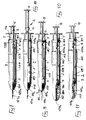
- the syringe according to the invention comprises an outer cylindrical body 1 having a front end 1 a shaped to connect to a needle, not shown as it can be of known type, and a rear end 1 b provided with a gripping flange. Within the cylindrical body 1 there slides a plunger 2 provided with a seal element 3 and a rod 4 terminating with a gripping flare 5.
- the rod 4 carries a frusto-conical portion 6 which converges towards the seal element 3 and has its major diameter substantially equal to or slightly less than the inner diameter of the cylindrical body 1, and its minor diameter less than the diameter of the plunger 2.
- a toroidal split-ring 7 which when in its rest state has an outer diameter greater than the inner diameter of the cylindrical body 1 and an inner diameter equal to the diameter of the rod 4, is located about the minor diameter region 8 of the portion 6 before initial use, and is therefore housed within the cylindrical body 1 in the position shown in Figure 1, in a deformed contracted state about the minor diameter region 8 of the portion 6, as can be also seen in Figure 2.
- the cylindrical body 1 At a short distance from its rear end 1 b , the cylindrical body 1 comprises an annular bulge 9 with an inner diameter equal to the maximum diameter of the frusto-conical portion 6 plus the width of the split-ring 7.
- the split-ring 7 is contracted about the minor diameter region 8 of the frusto-conical portion 6, and the plunger 2 is inserted completely into the cylindrical body 1, with the ring 7 in an intermediate position between the end 1 a of the cylindrical body 1 and the annular bulge 9.
- the syringe For its use, the syringe must be filled by drawing the medicinal liquid in by withdrawing the plunger 2 rearward. During this stage, as shown in Figure 3, the ring 7 is pulled by the rod 4 towards the annular bulge 9, into which it becomes insterted by opening out elastically into its rest state, shown in Figure 4.
- the liquid intake stage can then be continued until the syringe is filled with the required volume of medicinal liquid, without any further movement of the ring 7 which remains securely housed in its seat, whereas the plunger 2 can be moved to expel residual air or the like before inserting the needle into the patient's body for injecting the medicament.
- the plunger 2 is driven in to expel the liquid contained in the syringe, until the frusto-conical portion 6 comes into contact with the split-ring 7.
- the action of the surface of the portion 6 causes the ring 7 to widen out into its dilated state shown in Figure 6, with its inner diameter equal to the maximum diameter of the portion 6, so allowing the portion 6 to pass through as shown in Figure 5, and enabling the plunger 2 to terminate its stroke in order to completely expel the contained liquid.
- the flat rear surface 6 a of the frusto-conical portion 6 has a diameter substantially equal to or slightly less than the inner diameter of the cylindrical body 1, even if the ring 7 is forced and/or fractured it will be absolutely impossible to withdraw the plunger 2 due to interference.
- the distance between the syringe front end 1 a and the bulge 9 and the distance between the front surface of the seal element 3 and the surface 6 a are such that the position to which the plunger 2 has advanced when the ring 7 abuts against the surface 6 a is such as not to allow sufficient liquid to be injected before this abutment occurs, and also such as to allow the ring 7 to be drawn into the bulge 9 during the intake stage with even the minimum usable dosage of medicinal liquid, so as to prevent situations occurring in which the plunger does not become blocked after the initial injection, either by accident or by purposeful manipulation.
- the syringe according to the invention is also provided with a cap 109 which is of transparent material to enable the quantity of liquid present in the syringe to be seen, and has at its front a hole 109 a for passage of the needle 101 a , the cap being provided in its rear part with at least two elastic tongues 110 having their free ends 110 a turned inwards in the manner of a hook and inserted, when under initial conditions, in respective slots 111 which open into the groove 108.
- a spring 112 for example of spiral type, which under initial conditions is compressed.
- the body 1 is also provided with an outer annular cavity 113 or several limited cavities, disposed in correspondence with the free ends 110 a of the tongues 110.
- the syringe For its use, the syringe must be filled by drawing the medicinal liquid in by withdrawing the plunger 2 rearward. During this stage, as shown in Figure 8, the ring 7 is pulled by the rod 4 towards the annular groove 108, into which it becomes inserted by opening out elastically into its rest state, in contact with the ends 110 a of the tongues 110.
- the liquid intake stage can then be continued until the syringe is filled with the required volume of medicinal liquid, without any further movement of the ring 7 which remains securely housed in its seat, whereas the plunger 2 can be moved to expel residual air or the like before inserting the needle into the patient for injecting the medicament.
- the plunger 2 is driven in to expel the liquid contained in the syringe, until the frusto-conical portion 6 comes into contact with the split-ring 7.
- the action of the surface of the portion 6 causes the ring 7 to widen out to an inner diameter equal to the maximum diameter of the portion 6, so allowing the portion 6 to pass and enabling the plunger 2 to terminate its stroke in order to completely expel the liquid contained in the syringe.
- the ring 7 has widened out to the maximum diameter of the groove 108, and its outer surface therefore acts against the ends 110 a of the tongues 110 to urge them outwards, as shown in Figure 9, so that they deflect until they become released from the engagement with the edge of the groove 108.
- the cap 109 then advances through a distance "a" equal to the needle terminal portion 114 which determines its maximum depth of insertion, so that it comes into contact with the skin of the patient, against which it remains until the injection is complete, while the ends 110 a of the tongues 110 rest against the outer wall of the body 1 in a position forward of the groove 108, so that they are unable to re-enter the relative slots 111.
- That wall of the cavity 113 located towards the rear of the syringe is undercut, and the rear wall of the end 110 a of the tongues 110 is shaped to correspond to this undercut.
- the tongues oppose any force which could tend to again move the cap 109 rearward, so keeping the needle covered and preventing any accidental pricking by the used needle.
- the needle 101 a can be formed with its axis inclined to the axis of advancement of the cap 109, or in any event not coinciding with the syringe axis. In this manner, when the cap slides forward the needle undergoes deflection until it is completely housed within the cap, where it then straightens so that its point is displaced sideways from the front hole 109 a of the cap 109, thus making any further retraction of the cap 109 and consequent exposure of the needle impossible, even under conditions of accidental or voluntary breakage or bending of the tongues 110.
- the dimensions of the syringe according to the invention can be freely chosen according to utilisation requirements, and material of various type can be used compatible with sterisability and absence of toxicity, and compatible with the medicinal substances injected.
Landscapes
- Health & Medical Sciences (AREA)
- Engineering & Computer Science (AREA)
- Hematology (AREA)
- Anesthesiology (AREA)
- Biomedical Technology (AREA)
- Heart & Thoracic Surgery (AREA)
- Vascular Medicine (AREA)
- Life Sciences & Earth Sciences (AREA)
- Animal Behavior & Ethology (AREA)
- General Health & Medical Sciences (AREA)
- Public Health (AREA)
- Veterinary Medicine (AREA)
- Environmental & Geological Engineering (AREA)
- Infusion, Injection, And Reservoir Apparatuses (AREA)
Claims (13)
Priority Applications (1)
| Application Number | Priority Date | Filing Date | Title |
|---|---|---|---|
| AT88830315T ATE77247T1 (de) | 1987-07-27 | 1988-07-22 | Selbstblockierende hypodermische spritze zum einmalgebrauch mit nadel-schutzkappe. |
Applications Claiming Priority (4)
| Application Number | Priority Date | Filing Date | Title |
|---|---|---|---|
| IT48229/87A IT1218154B (it) | 1987-07-27 | 1987-07-27 | Siringa ipodermica monouso autobloccante |
| IT4822987 | 1987-07-27 | ||
| IT8748624A IT1211922B (it) | 1987-11-19 | 1987-11-19 | Siringa ipodermica monouso autobloccante con cappuccio di protezione dell'ago |
| IT4862487 | 1987-11-19 |
Publications (3)
| Publication Number | Publication Date |
|---|---|
| EP0307367A2 EP0307367A2 (fr) | 1989-03-15 |
| EP0307367A3 EP0307367A3 (en) | 1989-10-25 |
| EP0307367B1 true EP0307367B1 (fr) | 1992-06-17 |
Family
ID=26329293
Family Applications (1)
| Application Number | Title | Priority Date | Filing Date |
|---|---|---|---|
| EP88830315A Expired EP0307367B1 (fr) | 1987-07-27 | 1988-07-22 | Seringue hypodermique autoblocante à usage unique, avec capuchon de protection de l'aiguille |
Country Status (5)
| Country | Link |
|---|---|
| US (1) | US4850968A (fr) |
| EP (1) | EP0307367B1 (fr) |
| JP (1) | JPH062162B2 (fr) |
| DE (1) | DE3872122T2 (fr) |
| ES (1) | ES2034381T3 (fr) |
Cited By (6)
| Publication number | Priority date | Publication date | Assignee | Title |
|---|---|---|---|---|
| US6918889B1 (en) | 1999-06-10 | 2005-07-19 | Sanofi-Synthelabo | Disposable injection device |
| US7101351B2 (en) | 2003-11-03 | 2006-09-05 | Becton, Dickinson And Company | Safety device for a syringe |
| US7118552B2 (en) | 2000-02-18 | 2006-10-10 | Astrazeneca Ab | Automatically operable safety shield system for syringes |
| US7344517B2 (en) | 2004-01-20 | 2008-03-18 | Becton, Dickinson And Company | Syringe having a retractable needle |
| US7468054B2 (en) | 2003-11-03 | 2008-12-23 | Becton, Dickinson And Company | Safety shield system for a syringe |
| WO2009152542A1 (fr) | 2008-06-16 | 2009-12-23 | Pharma Consult Ges.M.B.H. & Co Nfg Kg | Dispositif d'injection |
Families Citing this family (106)
| Publication number | Priority date | Publication date | Assignee | Title |
|---|---|---|---|---|
| FR2644349B1 (fr) * | 1989-03-20 | 1997-11-14 | Hammami Alain | Seringue a utilisation unique |
| US5090962A (en) * | 1989-04-28 | 1992-02-25 | Flp Enterprises, Inc. | Non-reusable syringe |
| WO1990013325A1 (fr) * | 1989-05-04 | 1990-11-15 | Western Medical Products Pty Limited | Seringue |
| NZ233522A (en) * | 1989-05-04 | 1992-12-23 | Western Med Prod Pty Ltd | Syringe with sheath protection of used needle |
| FR2648716B1 (fr) * | 1989-06-27 | 1991-09-13 | Guerineau Jean | Seringue a usage unique. combine seringue-aiguille, auto-escamotable dans un fourreau de protection |
| FR2650187B2 (fr) * | 1989-06-27 | 1992-01-17 | Guerineau Jean | Combine aiguille-seringue auto-escamotable |
| IT1230297B (it) * | 1989-07-05 | 1991-10-18 | Carmelo Lo Duca | Siringa utilizzabile una sola volta. |
| US5407431A (en) * | 1989-07-11 | 1995-04-18 | Med-Design Inc. | Intravenous catheter insertion device with retractable needle |
| US6096005A (en) | 1989-07-11 | 2000-08-01 | Mdc Investment Holdings, Inc. | Retractable needle medical devices |
| US5067947A (en) * | 1989-07-18 | 1991-11-26 | Tri/West Systems, Inc. | Syringe plunger rod mount |
| US5019044A (en) * | 1989-08-14 | 1991-05-28 | Tsao Chien Hua | Safety hypodermic syringe |
| FR2652006B1 (fr) * | 1989-09-15 | 1992-08-14 | Denis Roger | Dispositif de fabrication de seringues anticontagion. |
| US5254093A (en) * | 1990-02-12 | 1993-10-19 | Medical Appliances, Inc. | Non-reusable hypodermic syringe |
| US5019049A (en) * | 1990-02-20 | 1991-05-28 | Haining Michael L | Intravenous catheter and insertion device |
| ATE112690T1 (de) * | 1990-03-08 | 1994-10-15 | Blue Star Corp Sa | Spritze mit sich automatisch zurückziehender nadel. |
| US4982842A (en) * | 1990-06-04 | 1991-01-08 | Concord/Portex | Safety needle container |
| US5026354A (en) * | 1990-06-21 | 1991-06-25 | Kocses Joseph W | Safety syringe apparatus |
| EP0467173B1 (fr) * | 1990-07-19 | 1995-11-08 | Nardino Righi | Seringue de sécurité à usage unique |
| US5139489A (en) * | 1991-01-07 | 1992-08-18 | Smiths Industries Medical Systems, Inc. | Needle protection device |
| US5232454A (en) * | 1990-08-01 | 1993-08-03 | Smiths Industries Medical Systems, Inc. | Safety needle container |
| US5232455A (en) * | 1991-01-07 | 1993-08-03 | Smiths Industries Medical Systems, Inc. | Syringe with protective housing |
| US5106379A (en) * | 1991-04-09 | 1992-04-21 | Leap E Jack | Syringe shielding assembly |
| US5147303A (en) * | 1991-05-23 | 1992-09-15 | Martin Bret C | Disposable safety syringe |
| IT1253104B (it) * | 1991-07-02 | 1995-07-10 | Paolo Romagnoli | Siringa monouso |
| US5232447A (en) * | 1991-08-08 | 1993-08-03 | Jetfill, Inc. | Non-reusable syringe |
| FR2680110A1 (fr) * | 1991-08-09 | 1993-02-12 | Charron Jean Yves | Seringue jetable avec securite et verrouillage. |
| GB9118204D0 (en) * | 1991-08-23 | 1991-10-09 | Weston Terence E | Needle-less injector |
| US5215534A (en) * | 1991-12-02 | 1993-06-01 | Lawrence De Harde | Safety syringe system |
| US5613952A (en) * | 1991-12-23 | 1997-03-25 | Syringe Develpoment Partners | Safety syringe |
| US5395339A (en) * | 1992-01-31 | 1995-03-07 | Sherwood Medical Company | Medical device with sterile fluid pathway |
| US5176650A (en) * | 1992-02-10 | 1993-01-05 | Haining Michael L | Intravenous catheter and insertion device |
| AU665829B2 (en) * | 1992-04-21 | 1996-01-18 | Eastland Medical Systems Limited | An improved parenteral device |
| WO1993023312A1 (fr) | 1992-05-18 | 1993-11-25 | Smiths Industries Medical Systems, Inc. | Systeme de securite et de protection d'une aiguille |
| US5308332A (en) * | 1992-06-19 | 1994-05-03 | Square One Medical, Lp | Actuator spring for syringe sheaths |
| US5273541A (en) * | 1992-08-03 | 1993-12-28 | Robert Malenchek | Safety syringe |
| US5334144A (en) * | 1992-10-30 | 1994-08-02 | Becton, Dickinson And Company | Single use disposable needleless injector |
| US5993426A (en) | 1993-04-16 | 1999-11-30 | Sims Portex Inc. | Fluid absorbable needle sheath |
| DE69429306T2 (de) * | 1993-07-09 | 2002-10-17 | Terumo K.K., Tokio/Tokyo | Spritzenaufbau |
| US5573510A (en) * | 1994-02-28 | 1996-11-12 | Isaacson; Dennis R. | Safety intravenous catheter assembly with automatically retractable needle |
| ATE172882T1 (de) * | 1994-09-27 | 1998-11-15 | Delab | Sichere injektionsvorrichtung |
| US5531704A (en) * | 1995-03-03 | 1996-07-02 | Emk Enterprises, Llc | Needle puncture prevention device |
| US6090077A (en) | 1995-05-11 | 2000-07-18 | Shaw; Thomas J. | Syringe plunger assembly and barrel |
| US5601534A (en) * | 1995-06-07 | 1997-02-11 | The University Of Memphis | Disposable hypodermic syringe and needle combination |
| CA2167787C (fr) * | 1995-06-08 | 2002-12-17 | Elizabeth S. Nathan | Seringue non reutilisable |
| US5814017A (en) * | 1996-07-18 | 1998-09-29 | Safegard Medical Products, Inc. | Single use syringe device |
| US5776107A (en) | 1996-12-31 | 1998-07-07 | Delab | Injection device |
| US7445612B2 (en) | 1996-12-31 | 2008-11-04 | Société de Conseils de Recherches et d'Applications Scientifiques, S.A.S. | Safety injection device for a liquid or semi-solid composition |
| AU6719198A (en) * | 1997-02-12 | 1998-09-08 | Sergio Restelli | Disposable safety syringe |
| US7223258B2 (en) * | 1998-08-28 | 2007-05-29 | Becton Dickinson And Company | Safety shield assembly |
| GB2359754B (en) | 2000-03-03 | 2004-04-28 | Nmt Group Plc | Needle sheath |
| US6958055B2 (en) * | 1998-09-04 | 2005-10-25 | Nmt Group Plc | Retractable needle syringe including a sheath and an intravenous adapter |
| US6648855B2 (en) | 1999-08-23 | 2003-11-18 | Becton, Dickinson And Company | Safety needle assembly |
| US20020161336A1 (en) * | 1999-08-23 | 2002-10-31 | Becton, Dickinson And Company | Needle shield assembly |
| US6699217B2 (en) | 1999-08-23 | 2004-03-02 | Becton, Dickinson And Company | Safety needle assembly |
| US6780169B2 (en) | 1999-08-23 | 2004-08-24 | Becton, Dickinson And Company | Safety shield assembly |
| FR2799376B1 (fr) | 1999-10-07 | 2002-01-18 | Marc Brunel | Dispositif d'injection a usage unique |
| US8226617B2 (en) | 1999-11-04 | 2012-07-24 | Tyco Healthcare Group Lp | Safety shield apparatus and mounting structure for use with medical needle devices |
| US7198618B2 (en) | 1999-11-04 | 2007-04-03 | Tyco Healthcare Group Lp | Safety shield for medical needles |
| US7029461B2 (en) | 1999-11-04 | 2006-04-18 | Tyco Healthcare Group Lp | Safety shield for medical needles |
| US6280420B1 (en) | 1999-11-04 | 2001-08-28 | Specialized Health Products | Reaccessible medical needle safety devices and methods |
| US6592556B1 (en) | 2000-07-19 | 2003-07-15 | Tyco Healthcare Group Lp | Medical needle safety apparatus and methods |
| ES2332595T3 (es) | 1999-11-18 | 2010-02-09 | Tyco Healthcare Group Lp | Envoltura automatica de seguridad para agujas. |
| AU783693B2 (en) | 1999-11-29 | 2005-11-24 | Mdc Investment Holdings, Inc. | Combination safety needle assembly and medical apparatus |
| US7329238B2 (en) * | 1999-12-07 | 2008-02-12 | Specialized Health Products Inc. | Safety needle medical bearing devices |
| WO2001066179A1 (fr) * | 2000-03-06 | 2001-09-13 | Mdc Investment Holdings, Inc. | Seringue hypodermique a aiguille retractable |
| US7361159B2 (en) | 2001-03-02 | 2008-04-22 | Covidien Ag | Passive safety shield |
| US7144389B2 (en) | 2001-03-14 | 2006-12-05 | Tyco Healthcare Group, Lp | Safety shield for medical needles |
| AUPR373001A0 (en) * | 2001-03-14 | 2001-04-12 | Glenord Pty Ltd | Improved non-reusable syringe |
| MXPA03010647A (es) * | 2001-05-22 | 2004-03-02 | Becton Dickinson Co | Conjunto de cubierta para aguja que tiene una cubierta para aguja articulada. |
| US7220249B2 (en) | 2001-06-06 | 2007-05-22 | Becton, Dickinson And Company | Hinged needle shield assembly having needle cannula lock |
| ES2568255T3 (es) * | 2001-07-09 | 2016-04-28 | Becton Dickinson And Company | Unidad de protector de aguja que tiene un protector de aguja articulado y un bloqueo de cánula flexible |
| US6527742B1 (en) | 2001-11-14 | 2003-03-04 | Robert C. Malenchek | Safety syringe |
| US7001363B2 (en) | 2002-04-05 | 2006-02-21 | F. Mark Ferguson | Safety shield for medical needles |
| SG121744A1 (en) | 2002-11-06 | 2006-05-26 | Becton Dickinson Co | Flashback blood collection needle with needle shield |
| US20090204076A1 (en) * | 2003-02-03 | 2009-08-13 | Barry Peter Liversidge | Medical Injector |
| GB2398248A (en) | 2003-02-14 | 2004-08-18 | Scient Generics Ltd | Safety device with trigger mechanism |
| US7553296B2 (en) | 2003-02-14 | 2009-06-30 | Tyco Healthcare Group Lp | Safety device with trigger mechanism |
| US6926697B2 (en) * | 2003-05-13 | 2005-08-09 | Robert Malenchek | Adaptor for converting a non-safety syringe into a safety syringe |
| US7285110B2 (en) | 2003-06-10 | 2007-10-23 | P. Rowan Smith, Jr. | Retractable hypodermic safety syringe |
| JP2005021351A (ja) * | 2003-07-01 | 2005-01-27 | Kyo Meisei | ディスポーザブルシリンジ |
| IL157981A (en) | 2003-09-17 | 2014-01-30 | Elcam Medical Agricultural Cooperative Ass Ltd | Auto injector |
| US7497847B2 (en) | 2003-11-03 | 2009-03-03 | Becton, Dickinson And Company | Safety shield system for a syringe |
| US7604613B2 (en) | 2004-01-20 | 2009-10-20 | Beckton, Dickinson And Company | Syringe having a retractable needle |
| IL160891A0 (en) | 2004-03-16 | 2004-08-31 | Auto-mix needle | |
| ES2362188T3 (es) | 2004-08-16 | 2011-06-29 | Becton, Dickinson And Company | Aguja de extracción de sangre con área de visualización de reflujo o "flashback". |
| EP1666084A1 (fr) * | 2004-12-01 | 2006-06-07 | Societe de Conseils de Recherches et d'Applications Scientifiques (S.C.R.A.S) SAS | Dispositif pour l'injection d'un principe actif pharmaceutique |
| EP1666085A1 (fr) * | 2004-12-01 | 2006-06-07 | Societe de Conseils de Recherches et d'Applications Scientifiques (S.C.R.A.S) SAS | Dispositif d'injection d'un implant solide ou semi-solide |
| US8062252B2 (en) | 2005-02-18 | 2011-11-22 | Becton, Dickinson And Company | Safety shield system for a syringe |
| BRPI0708858A2 (pt) | 2006-03-21 | 2011-06-14 | Tyco Healthcare Group L.P. | protetor de seguranÇa em forma de anel de trava passivo para dispositivos de injeÇço |
| US8057431B2 (en) | 2006-12-21 | 2011-11-15 | B. Braun Melsungen Ag | Hinged cap for needle device |
| US8038654B2 (en) | 2007-02-26 | 2011-10-18 | Becton, Dickinson And Company | Syringe having a hinged needle shield |
| AU2009261314A1 (en) * | 2008-06-17 | 2009-12-23 | Denki Kagaku Kogyo Kabushiki Kaisha | Injector |
| US12097357B2 (en) | 2008-09-15 | 2024-09-24 | West Pharma. Services IL, Ltd. | Stabilized pen injector |
| AU2013211572B2 (en) * | 2009-06-26 | 2015-06-11 | Becton, Dickinson And Company | Passive reuse prevention syringe that uses a flange lock |
| SG177328A1 (en) * | 2009-06-26 | 2012-02-28 | Becton Dickinson Co | Passive reuse prevention syringe that uses a flange lock |
| CN101891380B (zh) | 2010-07-13 | 2012-07-04 | 长飞光纤光缆有限公司 | 一种大尺寸光纤预制棒及其光纤的制造方法 |
| RU2446836C1 (ru) * | 2010-10-28 | 2012-04-10 | Государственное образовательное учреждение высшего профессионального образования Новгородский государственный университет имени Ярослава Мудрого | Одноразовый шприц |
| FR2971424B1 (fr) | 2011-02-14 | 2013-11-29 | Marc Brunel | Seringue de securite |
| WO2013061290A1 (fr) * | 2011-10-26 | 2013-05-02 | Nanopass Technologies Ltd. | Dispositif d'administration de médicament intradermique à microaiguille présentant une fonctionnalité d'autoblocage |
| DK2950857T3 (da) * | 2013-02-04 | 2023-08-28 | Sanofi Aventis Deutschland | Indretning til en lægemiddeladministrationsanordning |
| US9415176B1 (en) * | 2015-01-22 | 2016-08-16 | West Pharmaceutical Services, Inc. | Autoinjector having an end-of-dose visual indicator |
| US20200330688A1 (en) * | 2019-04-19 | 2020-10-22 | Merit Medical Systems, Inc. | Syringe with backpressure preventer and associated methods |
| US11420094B2 (en) * | 2019-12-11 | 2022-08-23 | Cheryl Gaboriault | Training device for chewing and swallowing |
| US12605510B2 (en) | 2020-03-11 | 2026-04-21 | Becton Dickinson France | Plunger rod and syringe including same |
| AU2021250033A1 (en) * | 2020-03-31 | 2022-12-01 | Daikyo Seiko, Ltd. | Medical syringe plunger and medical finger grip |
| CN112999468B (zh) * | 2021-02-09 | 2023-07-04 | 上海康德莱医疗器械股份有限公司 | 一种安全注射器 |
Family Cites Families (6)
| Publication number | Priority date | Publication date | Assignee | Title |
|---|---|---|---|---|
| US1434381A (en) * | 1920-10-28 | 1922-11-07 | Sigmund A Giedroyc | Hypodermic syringe |
| GB551545A (en) * | 1942-01-13 | 1943-02-26 | Samuel James Everett | Improvements in or relating to hypodermic and like syringes |
| US3946732A (en) * | 1973-08-08 | 1976-03-30 | Ampoules, Inc. | Two-chamber mixing syringe |
| JPS5853352B2 (ja) * | 1979-10-03 | 1983-11-29 | 日本電信電話株式会社 | 音声合成器 |
| DE3107414C2 (de) * | 1981-02-27 | 1983-03-24 | B. Braun Melsungen Ag, 3508 Melsungen | Einmalspritze für den medizinischen Gebrauch |
| DE8701501U1 (de) * | 1987-01-28 | 1987-05-14 | Witta, Lars, 5800 Hagen | Injektionsspritze |
-
1988
- 1988-07-13 US US07/218,284 patent/US4850968A/en not_active Expired - Fee Related
- 1988-07-22 EP EP88830315A patent/EP0307367B1/fr not_active Expired
- 1988-07-22 ES ES198888830315T patent/ES2034381T3/es not_active Expired - Lifetime
- 1988-07-22 DE DE8888830315T patent/DE3872122T2/de not_active Expired - Fee Related
- 1988-07-27 JP JP63185683A patent/JPH062162B2/ja not_active Expired - Lifetime
Cited By (8)
| Publication number | Priority date | Publication date | Assignee | Title |
|---|---|---|---|---|
| US6918889B1 (en) | 1999-06-10 | 2005-07-19 | Sanofi-Synthelabo | Disposable injection device |
| US7118552B2 (en) | 2000-02-18 | 2006-10-10 | Astrazeneca Ab | Automatically operable safety shield system for syringes |
| US7220247B2 (en) | 2000-02-18 | 2007-05-22 | Astrazeneca Ab | Automatically operable safety shield system for syringes |
| US7500964B2 (en) | 2000-02-18 | 2009-03-10 | Astrazeneca Ab | Automatically operable safety shield system for syringes |
| US7101351B2 (en) | 2003-11-03 | 2006-09-05 | Becton, Dickinson And Company | Safety device for a syringe |
| US7468054B2 (en) | 2003-11-03 | 2008-12-23 | Becton, Dickinson And Company | Safety shield system for a syringe |
| US7344517B2 (en) | 2004-01-20 | 2008-03-18 | Becton, Dickinson And Company | Syringe having a retractable needle |
| WO2009152542A1 (fr) | 2008-06-16 | 2009-12-23 | Pharma Consult Ges.M.B.H. & Co Nfg Kg | Dispositif d'injection |
Also Published As
| Publication number | Publication date |
|---|---|
| DE3872122D1 (de) | 1992-07-23 |
| EP0307367A3 (en) | 1989-10-25 |
| EP0307367A2 (fr) | 1989-03-15 |
| JPS6443268A (en) | 1989-02-15 |
| JPH062162B2 (ja) | 1994-01-12 |
| US4850968A (en) | 1989-07-25 |
| DE3872122T2 (de) | 1993-02-04 |
| ES2034381T3 (es) | 1993-04-01 |
Similar Documents
| Publication | Publication Date | Title |
|---|---|---|
| EP0307367B1 (fr) | Seringue hypodermique autoblocante à usage unique, avec capuchon de protection de l'aiguille | |
| US4950241A (en) | Disposable syringe | |
| EP1551482B1 (fr) | Seringue a usage unique dotee d'un ecran protecteur | |
| US6416323B1 (en) | Aspirating dental syringe with needle shield | |
| US5658257A (en) | Syringe | |
| US6846302B2 (en) | Needle protector device | |
| US5338303A (en) | Safety syringes | |
| US6719730B2 (en) | Safety shield system for prefilled syringes | |
| US4944723A (en) | Universal disposable safety syringe system | |
| US5259840A (en) | Locking syringe | |
| US5000738A (en) | Protective syringe with frangible barrel | |
| US20030187401A1 (en) | Syringe with integral safety system | |
| US20040030294A1 (en) | Retractable needle single use safety syringe | |
| WO1992014504A1 (fr) | Protection pour aiguille | |
| JPH11226125A (ja) | 一回使用の安全注射器 | |
| EP1496964A1 (fr) | Systeme d'ecran de securite pour seringues | |
| JPH10113389A (ja) | ロック可能な安全遮蔽体を有する医用注入装置 | |
| US5201719A (en) | Disposable hypodermic needle and medication catridge | |
| EP1558310A1 (fr) | Protection passive de surete pour dispositifs d'injection | |
| CA1316784C (fr) | Seringue hypodermique jetable auto-bloquante, dote d'un fourreau protegeant l'aiguille | |
| CN119136867A (zh) | 用于注射器的安全装置 | |
| AU1983992A (en) | A syringe |
Legal Events
| Date | Code | Title | Description |
|---|---|---|---|
| PUAI | Public reference made under article 153(3) epc to a published international application that has entered the european phase |
Free format text: ORIGINAL CODE: 0009012 |
|
| AK | Designated contracting states |
Kind code of ref document: A2 Designated state(s): AT BE CH DE ES FR GB GR LI LU NL SE |
|
| PUAL | Search report despatched |
Free format text: ORIGINAL CODE: 0009013 |
|
| RHK1 | Main classification (correction) |
Ipc: A61M 5/315 |
|
| AK | Designated contracting states |
Kind code of ref document: A3 Designated state(s): AT BE CH DE ES FR GB GR LI LU NL SE |
|
| 17P | Request for examination filed |
Effective date: 19900319 |
|
| GRAA | (expected) grant |
Free format text: ORIGINAL CODE: 0009210 |
|
| AK | Designated contracting states |
Kind code of ref document: B1 Designated state(s): AT BE CH DE ES FR GB GR LI LU NL SE |
|
| PG25 | Lapsed in a contracting state [announced via postgrant information from national office to epo] |
Ref country code: SE Effective date: 19920617 Ref country code: NL Effective date: 19920617 Ref country code: GR Free format text: LAPSE BECAUSE OF FAILURE TO SUBMIT A TRANSLATION OF THE DESCRIPTION OR TO PAY THE FEE WITHIN THE PRESCRIBED TIME-LIMIT Effective date: 19920617 Ref country code: BE Effective date: 19920617 Ref country code: AT Effective date: 19920617 |
|
| REF | Corresponds to: |
Ref document number: 77247 Country of ref document: AT Date of ref document: 19920715 Kind code of ref document: T |
|
| REF | Corresponds to: |
Ref document number: 3872122 Country of ref document: DE Date of ref document: 19920723 |
|
| PG25 | Lapsed in a contracting state [announced via postgrant information from national office to epo] |
Ref country code: LU Free format text: LAPSE BECAUSE OF NON-PAYMENT OF DUE FEES Effective date: 19920731 |
|
| ET | Fr: translation filed | ||
| NLV1 | Nl: lapsed or annulled due to failure to fulfill the requirements of art. 29p and 29m of the patents act | ||
| REG | Reference to a national code |
Ref country code: ES Ref legal event code: FG2A Ref document number: 2034381 Country of ref document: ES Kind code of ref document: T3 |
|
| PLBE | No opposition filed within time limit |
Free format text: ORIGINAL CODE: 0009261 |
|
| STAA | Information on the status of an ep patent application or granted ep patent |
Free format text: STATUS: NO OPPOSITION FILED WITHIN TIME LIMIT |
|
| 26N | No opposition filed | ||
| PGFP | Annual fee paid to national office [announced via postgrant information from national office to epo] |
Ref country code: GB Payment date: 19950718 Year of fee payment: 8 |
|
| PGFP | Annual fee paid to national office [announced via postgrant information from national office to epo] |
Ref country code: ES Payment date: 19950726 Year of fee payment: 8 |
|
| PGFP | Annual fee paid to national office [announced via postgrant information from national office to epo] |
Ref country code: DE Payment date: 19950727 Year of fee payment: 8 |
|
| PGFP | Annual fee paid to national office [announced via postgrant information from national office to epo] |
Ref country code: FR Payment date: 19950728 Year of fee payment: 8 Ref country code: CH Payment date: 19950728 Year of fee payment: 8 |
|
| PG25 | Lapsed in a contracting state [announced via postgrant information from national office to epo] |
Ref country code: GB Effective date: 19960722 |
|
| PG25 | Lapsed in a contracting state [announced via postgrant information from national office to epo] |
Ref country code: ES Free format text: LAPSE BECAUSE OF EXPIRATION OF PROTECTION Effective date: 19960723 |
|
| PG25 | Lapsed in a contracting state [announced via postgrant information from national office to epo] |
Ref country code: LI Effective date: 19960731 Ref country code: CH Effective date: 19960731 |
|
| GBPC | Gb: european patent ceased through non-payment of renewal fee |
Effective date: 19960722 |
|
| REG | Reference to a national code |
Ref country code: CH Ref legal event code: PL |
|
| PG25 | Lapsed in a contracting state [announced via postgrant information from national office to epo] |
Ref country code: FR Effective date: 19970328 |
|
| PG25 | Lapsed in a contracting state [announced via postgrant information from national office to epo] |
Ref country code: DE Effective date: 19970402 |
|
| REG | Reference to a national code |
Ref country code: FR Ref legal event code: ST |
|
| REG | Reference to a national code |
Ref country code: ES Ref legal event code: FD2A Effective date: 19990601 |