EP0307399B1 - Ladevorrichtung - Google Patents
Ladevorrichtung Download PDFInfo
- Publication number
- EP0307399B1 EP0307399B1 EP19870902664 EP87902664A EP0307399B1 EP 0307399 B1 EP0307399 B1 EP 0307399B1 EP 19870902664 EP19870902664 EP 19870902664 EP 87902664 A EP87902664 A EP 87902664A EP 0307399 B1 EP0307399 B1 EP 0307399B1
- Authority
- EP
- European Patent Office
- Prior art keywords
- rollers
- roller
- framework
- adjacent
- flexible support
- Prior art date
- Legal status (The legal status is an assumption and is not a legal conclusion. Google has not performed a legal analysis and makes no representation as to the accuracy of the status listed.)
- Expired
Links
- 239000000463 material Substances 0.000 claims abstract description 14
- 230000007246 mechanism Effects 0.000 claims description 4
- 229920002430 Fibre-reinforced plastic Polymers 0.000 abstract description 2
- 239000011151 fibre-reinforced plastic Substances 0.000 abstract description 2
- 238000004519 manufacturing process Methods 0.000 abstract description 2
- 239000011449 brick Substances 0.000 description 3
- 239000000843 powder Substances 0.000 description 3
- 239000000853 adhesive Substances 0.000 description 1
- 230000001070 adhesive effect Effects 0.000 description 1
- 238000000034 method Methods 0.000 description 1
Images


Classifications
-
- B—PERFORMING OPERATIONS; TRANSPORTING
- B65—CONVEYING; PACKING; STORING; HANDLING THIN OR FILAMENTARY MATERIAL
- B65G—TRANSPORT OR STORAGE DEVICES, e.g. CONVEYORS FOR LOADING OR TIPPING, SHOP CONVEYOR SYSTEMS OR PNEUMATIC TUBE CONVEYORS
- B65G47/00—Article or material-handling devices associated with conveyors; Methods employing such devices
- B65G47/52—Devices for transferring articles or materials between conveyors i.e. discharging or feeding devices
-
- B—PERFORMING OPERATIONS; TRANSPORTING
- B65—CONVEYING; PACKING; STORING; HANDLING THIN OR FILAMENTARY MATERIAL
- B65G—TRANSPORT OR STORAGE DEVICES, e.g. CONVEYORS FOR LOADING OR TIPPING, SHOP CONVEYOR SYSTEMS OR PNEUMATIC TUBE CONVEYORS
- B65G21/00—Supporting or protective framework or housings for endless load-carriers or traction elements of belt or chain conveyors
- B65G21/10—Supporting or protective framework or housings for endless load-carriers or traction elements of belt or chain conveyors movable, or having interchangeable or relatively movable parts; Devices for moving framework or parts thereof
- B65G21/14—Supporting or protective framework or housings for endless load-carriers or traction elements of belt or chain conveyors movable, or having interchangeable or relatively movable parts; Devices for moving framework or parts thereof to allow adjustment of length or configuration of load-carrier or traction element
-
- B—PERFORMING OPERATIONS; TRANSPORTING
- B65—CONVEYING; PACKING; STORING; HANDLING THIN OR FILAMENTARY MATERIAL
- B65G—TRANSPORT OR STORAGE DEVICES, e.g. CONVEYORS FOR LOADING OR TIPPING, SHOP CONVEYOR SYSTEMS OR PNEUMATIC TUBE CONVEYORS
- B65G57/00—Stacking of articles
- B65G57/02—Stacking of articles by adding to the top of the stack
- B65G57/03—Stacking of articles by adding to the top of the stack from above
- B65G57/06—Gates for releasing articles
Definitions
- This application relates to a device for accurate placement of sheets in a press, for example, for manufacturing printed circuit boards or fibre reinforced plastic panels.
- One purpose of the present invention is to provide a device which will allow sheets to be consistently and accurately placed in the press.
- This invention accordingly consists of a device for accurate placement of sheet material
- a framework characterised in having a first and second fixed roller transversely arranged adjacent the ends of the framework, a third and a fourth slidable and rotatable roller interdisposed between the first and second rollers, a flexible support member extending from each of the fixed rollers and round the adjacent roller to a fixture on the framework, the third and fourth rollers being in a support position when the rollers are adjacent to each other near the centre of the framework and in a release position when the third roller is adjacent the first roller and the fourth roller is adjacent the second roller, whereby sheet material placed on the flexible members in the support position peels away from the members as the third and fourth rollers move symmetrically towards the release position.
- each fixture on the framework is located adjacent to and in a plane higher than the axial plane of the associated fixed roller.
- slots for the third and fourth rollers are provided in the framework, to allow axial spigots of the rollers to slide therein.
- a slide mechanism on the framework can be provided for the axial spigots of the third and fourth roller.
- the flexible support members extend along the full length of the rollers.
- the fixed rollers have a resilient biassing means such that when axial spigots of the third and fourth rollers slide symmetrically towards the release position, the flexible support members wind onto the fixed rollers.
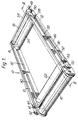
- the device generally indicated at 10 includes a general framework having two longitudinal members 12 and two transversely extending bars 14 and 15.
- a first roller 16 and a second roller 18 are attached transversely between the ends of the two longitudinal members 12.
- the rollers 16 and 18 are rotatable about axial spigots 17 and 19 respectively as shown in Figure 3.
- Resilient biassing means 21 are incorporated within the rollers 16 and 18, the purpose of the resilient biassing means will become apparent later in the description.
- a third roller 22 and a fourth roller 24 which are interdisposed between the first roller 16, and the second roller 18.
- the four rollers are preferably arranged to be substantially in parallel between the two longitudinal members 12.
- Axial spigots 26, one at each end of the roller 22 and axial spigots 28, one at each end of roller 24 extend through slots 30 and 32, formed in the longitudinal members 12.
- Slots 30 extending from adjacent the roller 16 and slots 32 extending from adjacent the roller 18 are of such a length that the spigots 26 and spigots 28 can slide from a release position, adjacent to the rollers 16 and 18 respectively, towards the centre of the device 10 to a support position.
- a flexible support member 34 is connected to the roller 16 underneath and round the adjacent roller 22 to the transversely extending bar 14 of the framework.
- a flexible support member 36 is connected to the roller 18 underneath and round the adjacent roller 24 to the transversely extending bar 15 of the framework.
- the bars 14 and 15 of the framework lie above and adjacent the rollers 16 and 18 respectively.
- the flexible member 34 and 36 extend along the full length of the rollers.
- Identical pulleys 42, 44 and cables 46, 52 are arranged on the outer sides of the longitudinal members 12 to allow axial spigots 26 and 28 to slide away from their release position, as shown in Figures 1 and 3 to the support position as shown in Figure 2.
- the pulley 42 is rotatably mounted on the longitudunal member 12 adjacent the roller 16.
- the pulley 44 is provided on the axial spigot 26.
- the cable 46 is connected to a axial spigot 28.
- the cable 46 passes underneath the pulley 44, underneath and round the pulley 42 and through a guide hole 48 formed in an extension 50 which is attached to the member 12 adjacent the roller 18.
- the sliding action for the axial spigot 26 is provided by connecting the cable 52 directly to the axial spigot 26 and passing it through the guide hole 48.
- the two cables 46 and 52 through the guide hole 48 on each side of the longitudinal members 12 are connected to a pull rod 54.
- the device 10 has to be positioned directly over a top of a press (not shown).
- the device 10, for example, can be arranged on a trolley (not shown) where the height can be adjustable for positioning.
- a trolley comprising the device 10 can be arranged on a track, allowing the trolley to move in and out of the press.
- the pull rod 54 is pulled away from the position adjacent the roller 18 in a direction as shown in Figures 1 and 3.
- the cables 46 and 52 cause the axial spigots 26 and 28 to slide symmetrically along the slots 30 and 32 respectively towards the support position from the release position as shown by chain-dotted lines in Figure 3.
- the sliding action of the axial spigots 26 and 28 allows the rollers 16 and 18 to rotate and unwind the flexible support sheets 34 and 36 from the rollers 16 and 18 respectively.
- the rollers 22 and 24 also rotate due to the unwinding of the flexible support members 34 and 36.
- the area within the device is substantially enclosed by the flexible support members 34 and 36 when the two rollers 22 and 24 have completed their movements.
- a material sheet 60 is placed on the extended flexible support sheets 34 and 36.
- the pull rod 54 is then allowed to move towards its normal position adjacent the roller 18.
- the flexible support member 34 and 36 peel away from the material sheet 60 allowing it to drop into the press when the support provided by the flexible sheets 34 and 36 is no longer available.
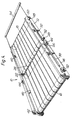
- a series of flexible support bands 40 can be provided as shown in Figure 4.
- the two longitudinal members 12 of the framework can be replaced by circular rods.
- the axial spigots 26 and 28 of the rollers 16 and 18 respectively can be connected to slide mechanisms which can slide along the circular rods and provide the necessary sliding action.
- An attachment arrangement for the rollers 16 and 18 will have to be provided at the ends of the two circular rods.
- the material sheet 60 must not be greater than the area defined between the two rollers 22 and 24 and the two longitudinal Sections 12, when the device 10 is in its inoperative position.
- one of the longitudinal member 12 can be removed and the remaining longitudinal member 12 can be reinforced so that it provides the support for the rollers and the bars 14, 15.
- Pulleys 42, 44 and cables 46, 52 on the removed side of the longitudinal member 12 will also be eliminated. With this arrangement the arterial sheet larger than the length of the rollers and bars 14. 15 can be supported.
- the invention is not restricted for accurate placement of sheet material in the press. It could, for example, be used for stacking up sheet material in a warehouse or for unloading sheet material for transportation on a conveyor belt.
Landscapes
- Engineering & Computer Science (AREA)
- Mechanical Engineering (AREA)
- Casting Or Compression Moulding Of Plastics Or The Like (AREA)
- Stacking Of Articles And Auxiliary Devices (AREA)
- Intermediate Stations On Conveyors (AREA)
- Discharge By Other Means (AREA)
- Processing And Handling Of Plastics And Other Materials For Molding In General (AREA)
Claims (9)
Priority Applications (1)
| Application Number | Priority Date | Filing Date | Title |
|---|---|---|---|
| AT87902664T ATE62888T1 (de) | 1986-05-13 | 1987-05-12 | Ladevorrichtung. |
Applications Claiming Priority (4)
| Application Number | Priority Date | Filing Date | Title |
|---|---|---|---|
| GB868611642A GB8611642D0 (en) | 1986-05-13 | 1986-05-13 | Loading device |
| GB8611642 | 1986-05-13 | ||
| GB868619048A GB8619048D0 (en) | 1986-08-05 | 1986-08-05 | Loading device |
| GB8619048 | 1986-08-05 |
Publications (2)
| Publication Number | Publication Date |
|---|---|
| EP0307399A1 EP0307399A1 (de) | 1989-03-22 |
| EP0307399B1 true EP0307399B1 (de) | 1991-04-24 |
Family
ID=26290760
Family Applications (1)
| Application Number | Title | Priority Date | Filing Date |
|---|---|---|---|
| EP19870902664 Expired EP0307399B1 (de) | 1986-05-13 | 1987-05-12 | Ladevorrichtung |
Country Status (3)
| Country | Link |
|---|---|
| EP (1) | EP0307399B1 (de) |
| JP (1) | JPH01502740A (de) |
| WO (1) | WO1987006918A1 (de) |
Cited By (1)
| Publication number | Priority date | Publication date | Assignee | Title |
|---|---|---|---|---|
| WO2025262087A1 (de) * | 2024-06-17 | 2025-12-26 | Siempelkamp Maschinen- Und Anlagenbau Gmbh | Vorrichtung und verfahren zum transport von, aus einer, insbesondere schüttgut aufweisenden, bewegten bahnware erzeugten, aufeinander folgend angeordneten, bahnwarenabschnitten, sowie anlage zur erzeugung von bahnwarenabschnitten |
Families Citing this family (4)
| Publication number | Priority date | Publication date | Assignee | Title |
|---|---|---|---|---|
| IT1395447B1 (it) * | 2009-07-24 | 2012-09-21 | Progetto C S R L | Metodo per l'indirizzamento di articoli sostanzialmente planari da una linea di convogliamento a sottostanti mezzi di ricevimento, e sistema che lo attua |
| JP6202689B2 (ja) * | 2015-11-04 | 2017-09-27 | 株式会社エイチアンドエフ | 搬送パレット、当該搬送パレットから軟化させた繊維強化樹脂を取り出す取り出し方法及びプレスセット |
| CN114474502A (zh) * | 2020-11-13 | 2022-05-13 | 上海宏嘉高新复合面料有限公司 | 一种多功能薄膜标准控制装置 |
| CH720818A1 (de) * | 2023-05-31 | 2024-12-13 | Ferag Ag | Kommissionieranlage |
Family Cites Families (4)
| Publication number | Priority date | Publication date | Assignee | Title |
|---|---|---|---|---|
| US1793006A (en) * | 1929-11-16 | 1931-02-17 | Edward J O'neill | Bed |
| US3631812A (en) * | 1969-11-04 | 1972-01-04 | Charles L Winslow Jr | Flexible hopper closure actuating mechanism |
| IT1167802B (it) * | 1981-01-02 | 1987-05-20 | Longinotti Spa | Dosatore ed alimentatore per materiale sfuso in uno stampo di macchine per la formazione di mationelle di cemento o simili |
| US4460110A (en) * | 1982-03-09 | 1984-07-17 | Esko Pollto Oy | Openable closing device for freight or storage tanks |
-
1987
- 1987-05-12 EP EP19870902664 patent/EP0307399B1/de not_active Expired
- 1987-05-12 WO PCT/GB1987/000318 patent/WO1987006918A1/en not_active Ceased
- 1987-05-12 JP JP62502985A patent/JPH01502740A/ja active Pending
Cited By (1)
| Publication number | Priority date | Publication date | Assignee | Title |
|---|---|---|---|---|
| WO2025262087A1 (de) * | 2024-06-17 | 2025-12-26 | Siempelkamp Maschinen- Und Anlagenbau Gmbh | Vorrichtung und verfahren zum transport von, aus einer, insbesondere schüttgut aufweisenden, bewegten bahnware erzeugten, aufeinander folgend angeordneten, bahnwarenabschnitten, sowie anlage zur erzeugung von bahnwarenabschnitten |
Also Published As
| Publication number | Publication date |
|---|---|
| JPH01502740A (ja) | 1989-09-21 |
| EP0307399A1 (de) | 1989-03-22 |
| WO1987006918A1 (en) | 1987-11-19 |
Similar Documents
| Publication | Publication Date | Title |
|---|---|---|
| ATA385283A (de) | Transportfilz fuer die fuehrung einer faserstoffbahn und verfahren fuer dessen herstellung | |
| US4116481A (en) | Lifting slings and a method for producing same | |
| DE1511853A1 (de) | Verfahren und Vorrichtung zum Verpacken von Gegenstaenden in Folien aus thermoplastischem Material | |
| EP0307399B1 (de) | Ladevorrichtung | |
| FI77205B (fi) | Anlaeggning foer hopsaettning av staplar av med ribbor aotskilt virke. | |
| DE4116026A1 (de) | Basisplattenfoerdereinrichtung | |
| EP0108496A1 (de) | Übergabeeinrichtung für Gegenstände | |
| FI80003C (fi) | Foerfarande och anordning foer att mata fjaellartat nedfallande tryckprodukter till en mellanstation. | |
| DE3884275T2 (de) | Vorrichtung zum Entfernen von Haspeln. | |
| CN117208341A (zh) | 一种摩托车内胎生产用打包装置 | |
| EP0327048B1 (de) | Apparat zum Aufwickeln von bogenförmigem Formmaterial | |
| CA1323558C (en) | Apparatus for the manufacturing of insulating chutes | |
| SK283382B6 (sk) | Zariadenie na výrobu zavinutí z plátov cesta a deliacich plátov | |
| JPS6180760U (de) | ||
| EP0386094B1 (de) | Herstellung eines biegsamen verstärkten polymeren materials | |
| EP3705427A1 (de) | Abnahmevorrichtung zum automatisierten abnehmen von gewebematerialteilen, ein verfahren zum automatisierten abnehmen von gewebematerialteilen und eine produktionsanlage mit einer fördereinrichtung und einer abnahmevorrichtung | |
| JPH07501283A (ja) | 六角セルハニカムコアを形成するための装置とプロセス、及びこれにより形成されたコア | |
| CN216863137U (zh) | 一种自动模切设备 | |
| CN117048958A (zh) | 卷材用收卷捆扎装置 | |
| DE2111160B2 (de) | Vorrichtung zum foerdern von metallisierten baendern in einer folienmaterial bearbeitenden plattenpresse | |
| IE46816B1 (en) | Process for the production of hose in vulcanizable elastomeric material | |
| CN109850246B (zh) | 一种型材自动输送以及包装设备 | |
| DE1952429B2 (de) | Foerdervorrichtung | |
| KR102765215B1 (ko) | 농업용 필름 폴딩장치 | |
| DE2418445B2 (de) | Verfahren und vorrichtung zum schrittweise fortlaufenden tiefziehen von in einem spannrahmen gehaltenen und in diesem erwaermten kunststoff-folien |
Legal Events
| Date | Code | Title | Description |
|---|---|---|---|
| PUAI | Public reference made under article 153(3) epc to a published international application that has entered the european phase |
Free format text: ORIGINAL CODE: 0009012 |
|
| 17P | Request for examination filed |
Effective date: 19881103 |
|
| AK | Designated contracting states |
Kind code of ref document: A1 Designated state(s): AT BE CH DE FR GB IT LI LU NL SE |
|
| 17Q | First examination report despatched |
Effective date: 19900503 |
|
| GRAA | (expected) grant |
Free format text: ORIGINAL CODE: 0009210 |
|
| AK | Designated contracting states |
Kind code of ref document: B1 Designated state(s): AT BE CH DE FR GB IT LI LU NL SE |
|
| REF | Corresponds to: |
Ref document number: 62888 Country of ref document: AT Date of ref document: 19910515 Kind code of ref document: T |
|
| ITF | It: translation for a ep patent filed | ||
| REF | Corresponds to: |
Ref document number: 3769646 Country of ref document: DE Date of ref document: 19910529 |
|
| PG25 | Lapsed in a contracting state [announced via postgrant information from national office to epo] |
Ref country code: LU Free format text: LAPSE BECAUSE OF NON-PAYMENT OF DUE FEES Effective date: 19910531 |
|
| ET | Fr: translation filed | ||
| PLBE | No opposition filed within time limit |
Free format text: ORIGINAL CODE: 0009261 |
|
| STAA | Information on the status of an ep patent application or granted ep patent |
Free format text: STATUS: NO OPPOSITION FILED WITHIN TIME LIMIT |
|
| 26N | No opposition filed | ||
| PGFP | Annual fee paid to national office [announced via postgrant information from national office to epo] |
Ref country code: FR Payment date: 19930408 Year of fee payment: 7 Ref country code: AT Payment date: 19930408 Year of fee payment: 7 |
|
| PGFP | Annual fee paid to national office [announced via postgrant information from national office to epo] |
Ref country code: SE Payment date: 19930414 Year of fee payment: 7 |
|
| PGFP | Annual fee paid to national office [announced via postgrant information from national office to epo] |
Ref country code: GB Payment date: 19930415 Year of fee payment: 7 |
|
| PGFP | Annual fee paid to national office [announced via postgrant information from national office to epo] |
Ref country code: CH Payment date: 19930419 Year of fee payment: 7 |
|
| PGFP | Annual fee paid to national office [announced via postgrant information from national office to epo] |
Ref country code: DE Payment date: 19930421 Year of fee payment: 7 |
|
| PGFP | Annual fee paid to national office [announced via postgrant information from national office to epo] |
Ref country code: BE Payment date: 19930427 Year of fee payment: 7 |
|
| PGFP | Annual fee paid to national office [announced via postgrant information from national office to epo] |
Ref country code: NL Payment date: 19930531 Year of fee payment: 7 |
|
| PG25 | Lapsed in a contracting state [announced via postgrant information from national office to epo] |
Ref country code: GB Effective date: 19940512 Ref country code: AT Effective date: 19940512 |
|
| PG25 | Lapsed in a contracting state [announced via postgrant information from national office to epo] |
Ref country code: SE Effective date: 19940513 |
|
| PG25 | Lapsed in a contracting state [announced via postgrant information from national office to epo] |
Ref country code: LI Effective date: 19940531 Ref country code: CH Effective date: 19940531 Ref country code: BE Effective date: 19940531 |
|
| BERE | Be: lapsed |
Owner name: THE SECRETARY OF STATE FOR TRADE AND INDUSTRY IN Effective date: 19940531 |
|
| PG25 | Lapsed in a contracting state [announced via postgrant information from national office to epo] |
Ref country code: NL Effective date: 19941201 |
|
| GBPC | Gb: european patent ceased through non-payment of renewal fee |
Effective date: 19940512 |
|
| NLV4 | Nl: lapsed or anulled due to non-payment of the annual fee | ||
| EUG | Se: european patent has lapsed |
Ref document number: 87902664.9 Effective date: 19941210 |
|
| PG25 | Lapsed in a contracting state [announced via postgrant information from national office to epo] |
Ref country code: FR Effective date: 19950131 |
|
| REG | Reference to a national code |
Ref country code: CH Ref legal event code: PL |
|
| PG25 | Lapsed in a contracting state [announced via postgrant information from national office to epo] |
Ref country code: DE Effective date: 19950201 |
|
| EUG | Se: european patent has lapsed |
Ref document number: 87902664.9 |
|
| REG | Reference to a national code |
Ref country code: FR Ref legal event code: ST |
|
| PG25 | Lapsed in a contracting state [announced via postgrant information from national office to epo] |
Ref country code: IT Free format text: LAPSE BECAUSE OF NON-PAYMENT OF DUE FEES;WARNING: LAPSES OF ITALIAN PATENTS WITH EFFECTIVE DATE BEFORE 2007 MAY HAVE OCCURRED AT ANY TIME BEFORE 2007. THE CORRECT EFFECTIVE DATE MAY BE DIFFERENT FROM THE ONE RECORDED. Effective date: 20050512 |