EP0307560A1 - Auflageelement - Google Patents
Auflageelement Download PDFInfo
- Publication number
- EP0307560A1 EP0307560A1 EP88110600A EP88110600A EP0307560A1 EP 0307560 A1 EP0307560 A1 EP 0307560A1 EP 88110600 A EP88110600 A EP 88110600A EP 88110600 A EP88110600 A EP 88110600A EP 0307560 A1 EP0307560 A1 EP 0307560A1
- Authority
- EP
- European Patent Office
- Prior art keywords
- polyamide
- storage element
- element according
- polyamide part
- groove
- Prior art date
- Legal status (The legal status is an assumption and is not a legal conclusion. Google has not performed a legal analysis and makes no representation as to the accuracy of the status listed.)
- Granted
Links
- 239000004952 Polyamide Substances 0.000 claims abstract description 27
- 229920002647 polyamide Polymers 0.000 claims abstract description 27
- 229920002292 Nylon 6 Polymers 0.000 claims description 3
- 230000003993 interaction Effects 0.000 description 1
- 238000003466 welding Methods 0.000 description 1
Images
Classifications
-
- B—PERFORMING OPERATIONS; TRANSPORTING
- B62—LAND VEHICLES FOR TRAVELLING OTHERWISE THAN ON RAILS
- B62D—MOTOR VEHICLES; TRAILERS
- B62D33/00—Superstructures for load-carrying vehicles
- B62D33/02—Platforms; Open load compartments
- B62D33/023—Sideboard or tailgate structures
-
- B—PERFORMING OPERATIONS; TRANSPORTING
- B62—LAND VEHICLES FOR TRAVELLING OTHERWISE THAN ON RAILS
- B62D—MOTOR VEHICLES; TRAILERS
- B62D33/00—Superstructures for load-carrying vehicles
- B62D33/02—Platforms; Open load compartments
Definitions
- the invention relates to a bearing element with the features of the preamble of claim 1.
- the object of the invention is to improve the known bearing element in such a way that the least possible wear attack is given even under rough operating conditions of a motor vehicle, in particular a truck.
- a impact-resistant polyamide part provides a surprisingly high resistance to wear. Since the polyamide part is also interchangeable, it can be easily replaced. It is not necessary to replace the entire bearing element or to replace it by welding or the like.
- the polyamide part is at least slightly displaceable.
- the frame profile which rests on the bearing element or more precisely on the polyamide part and, due to the vibrations etc., moves with respect to the bearing element, if only slightly, can move together with the polyamide part in such a configuration.
- the relative movement occurs, at least partly. between the polyamide part and the bearing element.
- Design that the polyamide part is arranged to be slightly longitudinally displaceable is also of independent importance.
- the movable part does not necessarily have to be made of polyamide.
- the polyamide part can advantageously be designed in the form of a strip and arranged in a groove in the bearing element. It is preferred here in order to provide the displaceability that the groove has a greater length than the bar. The bar can thus be slid lengthways in the groove.
- the groove is designed in the form of a dovetail guide and the bar has corresponding flank areas that slide in the dovetail guide.
- the storage element can be arranged, for example, on the bottom of a truck side wall for the storage of overlying frame profiles.
- the bearing element can also be designed as a protruding bearing cheek of a frame profile itself. In most cases, the storage cheek extends vertically when installed and, due to a clamp bracket, supports another mounting profile.
- the area of the socket profile, which interacts with the support cheek of an adjacent socket profile, can be designed in the same way in the form of a bearing element described here. In this embodiment, two polyamide parts lie one on top of the other in the stored state.
- this part consists of polyamide 6.
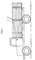
- a truck is first shown schematically, which in its loading area Has wall elements 1, which are held by socket profiles 2.
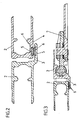
- FIG. 2 shows a cross-section of an area of interaction of such socket profiles 2.
- the frame profile 2 on the left in the drawing has a mounting cheek 3 which bears the frame profile 2 on the right in the drawing.
- a polyamide part 6 is held in a groove 5 in the bearing cheek 3 as well as in the counter-bearing area 4 of the frame profile 2 on the right in the drawing.
- the polyamide part is specifically polyamide 6.
- the grooves 5 are undercut in their side regions and the polyamide parts 6 are shaped accordingly for holding them.
- the grooves 5 are provided at least in one of the parts, the storage cheek 3 or the mounting area 4 with a greater length than the polyamide parts 6, so that a polyamide part 6 can move, even if only slightly, in a groove 5 in the longitudinal direction.
- FIG. 3 two further frame profiles 2 are shown in cross-section, in which the frame profile 2 on the right in the drawing is formed with a bearing cheek 3 and in which exemplary embodiment only one polyamide part 6 is arranged in the bearing cheek 3.
- the frame profile 2 shown on the right in FIG. 3 has a locking mechanism with a locking lever 7, as a result of which a clamping holding force for holding the frame profile 2 on the left in FIG. 3 can be produced.
- a storage element with a notch-resistant strip made of polyamide also can be provided for lower support of the edge elements 1, on the edge of the loading floor surface.
Landscapes
- Engineering & Computer Science (AREA)
- Chemical & Material Sciences (AREA)
- Combustion & Propulsion (AREA)
- Transportation (AREA)
- Mechanical Engineering (AREA)
- Body Structure For Vehicles (AREA)
- Motor Or Generator Frames (AREA)
- Piezo-Electric Or Mechanical Vibrators, Or Delay Or Filter Circuits (AREA)
- Supporting Of Heads In Record-Carrier Devices (AREA)
- Coupling Device And Connection With Printed Circuit (AREA)
- Switches With Compound Operations (AREA)
- Finger-Pressure Massage (AREA)
Abstract
Description
- Die Erfindung betrifft ein Lagerungselement mit den Merkmalen des Oberbegriffes des Anspruches 1.
- Bei Kraftfahrzeugen, insbesondere Lastkraftfahrzeugen, ist es bekannt, Bordwände oder Elemente von Bordwänden in einem Fassungsprofil zu lagern. Beispielsweise können schwenkbare Bordwände von Lastkraftwagen derartig ausgebildet sein. In den Lagerungsbereichen ergibt sich ein Problem durch einen relativ heftigen Verschleißangriff der Bordwände oder der Teile der Bordwände. Die rauhen Einsatzbedingungen eines Lastkraftwagens führen zu erheblichen Erschütterungen, welche sich auf die Bordwände und die Teile der Bordwände übertragen und in den Lagerungsbereichen aufzunehmen sind.
- Bislang mußten daher solche Lagerungselemente in relativ kurzen Abständen ausgetauscht oder erneuert werden.
- Im Hinblick auf den Stand der Technik stellt sich die Erfindung die Aufgabe, das bekannte Lagerungselement derart zu verbessern, daß ein möglichst geringer Verschleißangriff auch bei rauhen Einsatzbedingungen eines Kraftfahrzeuges, insbesondere eines Lastkraftfahrzeuges, gegeben ist.
- Diese Aufgabe ist bei einem Lagerungselement mit den Merkmalen des Anspruches 1 gelöst.
- Es hat sich gezeigt, daß ein kerbschlagfestes Polyamidteil dem Verschleißangriff einen überraschend hohen Widerstand entgegensetzt. Da das Polyamidteil darüber hinaus austauschbar angeordnet ist, kann es leicht ersetzt werden. Es ist nicht erforderlich, jeweils das gesamte Lagerungselement zu ersetzen oder durch Auftragsschweißung oder dergleichen etwa zu erneuern.
- In Ausgestaltung der Erfindung ist vorgesehen, daß das Polyamidteil zumindest geringfügig verschiebbar angeordnet ist. Das Fassungsprofil, welches auf dem Lagerungselement bzw. genauer auf dem Polyamidteil aufliegt und aufgrund der Erschütterungen etc. sich gegenüber dem Lagerelement, wenn auch nur geringfügig, bewegt, kann sich bei einer derartigen Ausgestaltung zusammen mit dem Polyamidteil bewegen. Die Relativbewegung tritt so, jedenfalls z.T. zwischen dem Polyamidteil und dem Lagerungselement auf. Das das Polyamidteil in seinem Fassungsbereich sehr glatt gearbeitet sein kann, entsprechend auch das Lagerungselement in dem Fassungsbereich für das Polyamidteil, ist bei der Relativbewegung zwischen dem Polyamidteil und dem Lagerungselement ein wesentlich geringerer Verschleißangriff gegeben als bei einer Relativbewegung zwischen dem Fassungsprofil und dem Polyamidteil.Der Gestaltung, daß das Polyamidteil geringfügig längsverschieblich angeordnet ist, kommt auch selbständige Bedeutung zu. Das verschiebliche Teil muß auch nicht notwendig aus Polyamid bestehen.
- Vorteilhaft kann das Polyamidteil in Form einer Leiste ausgebildet sein und in einer Nut in dem Lagerungselement angeordnet sein. Bevorzugt ist hier, um die Verschiebbarkeit zu ergeben, daß die Nut eine größere Länge aufweist als die Leiste. Damit ist die Leiste in der Nut längsversohiebbar.
- In vorteilhafter Ausgestaltung ist die Nut in Form einer Schwalbenschwanzführung ausgebildet und die Leiste weist entsprechende Flankenbereiche auf, die in der Schwalbenschwanzführung gleiten.
- Das Lagerungselement kann angeordnet sein etwa am Boden einer Lastwagenseitenwand zur Lagerung von aufliegenden Fassungsprofilen. Darüber hinaus kann das Lagerungselement aber auch als überstehende Lagerungswange eines Fassungsprofils selbst ausgebildet sein. Meist erstreckt sich die Lagerungswange im eingebauten Zustand senkrecht und lagert, aufgrund einer Klemmhalterung, ein weiteres Fassungsprofil. Der Bereich des Fassungsprofils, welcher mit der Lagerungswange eines benachbarten Fassungsprofils zusammenwirkt, kann in gleicher Weise in Form eines hier beschriebenen Lagerungselementes ausgebildet sein. Bei dieser Ausgestaltung liegen entsprechend im Lagerungszustand zwei Polyamidteile aufeinander.
- Hinsichtlich des kerbschlagfesten Polyamidteils ist besonders bevorzugt, daß dieses Teil aus Polyamid 6 besteht.
- Nachstehend ist die Erfindung noch anhand der beigefügten Zeichnung weiter im einzelnen erläutert, auf welcher zeigt:
- Fig. 1 eine Seitenansicht eines Lastwagens mit Fassungsprofilen;
- Fig. 2 einen Querschnitt durch zwei zusammenwirkende Fassungsprofile, von denen eines mit einer Lagerungswange ausgestattet ist und
- Fig. 3 einen weiteren Querschnitt durch zwei zusammenwirkende Fassungsprofile, wobei das eine Fassungsprofil einen Verriegelungsmechanismus besitzt.
- In Fig. 1 ist zunächst, schematisch, ein Lastkraftwagen dargestellt, welcher in seinem Beladungsbereich Wandelemente 1 besitzt, die durch Fassungsprofile 2 gehaltert werden.
- In Fig. 2 ist ein Zusammenwirkungsbereich solcher Fassungprofile 2 im Querschnitt dargestellt.
- Das in der Zeichnung linke Fassungsprofil 2 besitzt eine Lagerungswange 3, welcher das in der Zeichnung rechte Fassungsprofil 2 gehaltert anliegt. In der Lagerungswange 3 wie auch in dem Gegenlagerungsbereich 4 des in der Zeichnung rechten Fassungsprofils 2 ist jeweils in einer Nut 5 ein Polyamidteil 6 gehaltert. Bei dem Polyamidteil handelt es sich speziell um Polyamid 6.
- Die Nuten 5 sind in ihren Seitenbereichen hinterschnitten ausgebildet und entsprechend die Polyamidteile 6 zur Halterung darin geformt.
- Die Nuten 5 sind zumindestens in einem der Teile, der Lagerungswange 3 oder dem Halterungsbereich 4 mit einer größeren Länge vorgesehen, als die Polyamidteile 6, so daß ein Polyamidteil 6 sich, wenn auch nur geringfügig, in einer Nut 5 in Längsrichtung bewegen kann.
- In der Darstellung gemäß Fig. 3 sind zwei weitere Fassungsprofile 2 im Querschnitt dargestellt, bei welchen das in der Zeichnung rechte Fassungsprofil 2 mit einer Lagerungswange 3 ausgebildet ist und bei welchem Ausführungsbeispiel lediglich in der Lagerungswange 3 ein Polyamidteil 6 angeordnet ist. Das in der Fig. 3 rechts dargestellte Fassungsprofil 2 besitzt einen Verriegelungsmechanismus mit einem Verriegelungshebel 7, wodurch eine Klemmhalterungskraft zur Halterung des in der Fig. 3 linken Fassungsprofils 2 hervorbringbar ist.
- In der Zeichnung nicht dargestellt ist, daß ein Lagerungselement mit einer kerbeschlagfesten Leiste aus Polyamid auch zur unteren Abstützung der Randelemente 1, am Rand der Ladebodenfläche, vorgesehen sein kann.
- Die in der vorstehenden Beschreibung, Zeichnung und den Ansprüchen offenbarten Merkmale der Erfindung können sowohl einzeln als auch in beliebiger Kombination für die Verwirklichung der Erfindung in ihren verschiedensten Ausgestaltungen von Bedeutung sein.
Claims (7)
Priority Applications (1)
| Application Number | Priority Date | Filing Date | Title |
|---|---|---|---|
| AT88110600T ATE62877T1 (de) | 1987-07-20 | 1988-07-02 | Auflageelement. |
Applications Claiming Priority (2)
| Application Number | Priority Date | Filing Date | Title |
|---|---|---|---|
| DE8709930U | 1987-07-20 | ||
| DE8709930U DE8709930U1 (de) | 1987-07-20 | 1987-07-20 | Lagerungselement |
Publications (2)
| Publication Number | Publication Date |
|---|---|
| EP0307560A1 true EP0307560A1 (de) | 1989-03-22 |
| EP0307560B1 EP0307560B1 (de) | 1991-04-24 |
Family
ID=6810240
Family Applications (1)
| Application Number | Title | Priority Date | Filing Date |
|---|---|---|---|
| EP88110600A Expired - Lifetime EP0307560B1 (de) | 1987-07-20 | 1988-07-02 | Auflageelement |
Country Status (5)
| Country | Link |
|---|---|
| EP (1) | EP0307560B1 (de) |
| AT (1) | ATE62877T1 (de) |
| DE (2) | DE8709930U1 (de) |
| ES (1) | ES2008056B3 (de) |
| GR (1) | GR3001854T3 (de) |
Citations (6)
| Publication number | Priority date | Publication date | Assignee | Title |
|---|---|---|---|---|
| US3266837A (en) * | 1964-05-04 | 1966-08-16 | Highway Trailer Ind Inc | Convertible van |
| DE1605931A1 (de) * | 1967-01-23 | 1971-05-27 | Aluminium Press Walzwerk | Aus Leichtmetallprofilteilen bestehender abklappbarer Bordladen |
| DE2109332A1 (en) * | 1970-02-27 | 1971-09-16 | Oiles Industry Co Ltd | Bearings with lubricated thermoplastic resin coating |
| AT321740B (de) * | 1972-07-24 | 1975-04-10 | Vmw Ranshofen Berndorf Ag | Bordwand fuer nutzfahrzeuge |
| DE1964943B2 (de) * | 1969-12-24 | 1978-11-30 | Karl Schmidt Gmbh, 7107 Neckarsulm | Verwendung eines Polyamides |
| DD225676A1 (de) * | 1984-05-09 | 1985-08-07 | Niesky Waggonbau Veb | Arretierung fuer haubenverdecke an gueterwagen und container |
-
1987
- 1987-07-20 DE DE8709930U patent/DE8709930U1/de not_active Expired
-
1988
- 1988-07-02 DE DE8888110600T patent/DE3862552D1/de not_active Expired - Lifetime
- 1988-07-02 ES ES88110600T patent/ES2008056B3/es not_active Expired - Lifetime
- 1988-07-02 AT AT88110600T patent/ATE62877T1/de active
- 1988-07-02 EP EP88110600A patent/EP0307560B1/de not_active Expired - Lifetime
-
1991
- 1991-04-25 GR GR91400455T patent/GR3001854T3/el unknown
Patent Citations (6)
| Publication number | Priority date | Publication date | Assignee | Title |
|---|---|---|---|---|
| US3266837A (en) * | 1964-05-04 | 1966-08-16 | Highway Trailer Ind Inc | Convertible van |
| DE1605931A1 (de) * | 1967-01-23 | 1971-05-27 | Aluminium Press Walzwerk | Aus Leichtmetallprofilteilen bestehender abklappbarer Bordladen |
| DE1964943B2 (de) * | 1969-12-24 | 1978-11-30 | Karl Schmidt Gmbh, 7107 Neckarsulm | Verwendung eines Polyamides |
| DE2109332A1 (en) * | 1970-02-27 | 1971-09-16 | Oiles Industry Co Ltd | Bearings with lubricated thermoplastic resin coating |
| AT321740B (de) * | 1972-07-24 | 1975-04-10 | Vmw Ranshofen Berndorf Ag | Bordwand fuer nutzfahrzeuge |
| DD225676A1 (de) * | 1984-05-09 | 1985-08-07 | Niesky Waggonbau Veb | Arretierung fuer haubenverdecke an gueterwagen und container |
Also Published As
| Publication number | Publication date |
|---|---|
| DE8709930U1 (de) | 1988-11-17 |
| DE3862552D1 (de) | 1991-05-29 |
| EP0307560B1 (de) | 1991-04-24 |
| GR3001854T3 (en) | 1992-11-23 |
| ES2008056A4 (es) | 1989-07-16 |
| ES2008056B3 (es) | 1991-12-01 |
| ATE62877T1 (de) | 1991-05-15 |
Similar Documents
| Publication | Publication Date | Title |
|---|---|---|
| DE112018000009T5 (de) | Längseinsteller für einen Fahrzeugsitz | |
| EP1522442B1 (de) | Fahrzeugfestes Führungssytem und Verfahren zum Herstellen eines fahrzeugfesten Führungssystems | |
| DE4129497B4 (de) | 4-Wege-Sitzhöhenverstellung für einen Fahrzeugsitz | |
| AT390890B (de) | Antriebseinrichtung fuer schienenfahrzeuge mit einem adhaesions- und zahnradantrieb | |
| EP0609677A1 (de) | Halteelement zum vertikalen Fixieren einer in einen Fensterrahmen eines Kraftfahrzeuges einklebbaren Glasscheibe | |
| EP0872408B1 (de) | Anordnung in einem Cockpitbereich eines Kraftfahrzeuges | |
| DE3111466A1 (de) | Verstellvorrichtung zum verstellen eines sitzes, insbesondere eines kraftfahrzeugsitzes | |
| EP0307560A1 (de) | Auflageelement | |
| EP0593909A1 (de) | Kunststoff-Halteclip für Schutz-, Zierleisten oder dergleichen, insbesondere an Kraftfahrzeugen | |
| DE19732700B4 (de) | Rahmenanordnung für ein Deckelteil eines Fahrzeugdaches | |
| DE29718854U1 (de) | Profilrahmen, insbesondere U-Profilrahmen zur Halterung von Flächenelementen wie Glasscheiben, Kunststoffplatten o.dgl. | |
| WO2020178264A1 (de) | Längseinstellvorrichtung zur motorischen längseinstellung eines fahrzeugsitzes sowie fahrzeugsitz | |
| DE3878447T2 (de) | Rahmenprofil, das als strukturelement zur versteifung von anzeigetafeln, insbesondere von verkehrszeichen, geeignet ist, und das als sicherungselement fuer die schraubenbolzen, die fuer die befestigung der anzeigetafeln an entsprechenden stuetzpfaehlen vorgesehen sind, dient. | |
| DE8605022U1 (de) | Bordwandprofil mit Zurrschienenhalterung | |
| DE8816879U1 (de) | Lagerungselement | |
| DE10036790B4 (de) | Befestigungsanordnung zum Fügen von benachbarten Leichtbauplatten einer Fahrzeugtragstruktur | |
| DE9107593U1 (de) | Zusammengesetztes Türschild | |
| EP0703114B1 (de) | Schubladenascher für Fahrzeuge | |
| DE19642551B4 (de) | Arretiervorrichtung für ein Trittbrett und mit einer Arretiervorrichtung versehenes Trittbrett | |
| DE19933674B4 (de) | Verstellmechanismus für eine Lenksäule eines Kraftfahrzeugs | |
| DE3235609A1 (de) | Gleitschiene fuer fahrzeugsitze | |
| AT522977B1 (de) | Verfahren zur Herstellung einer Großkomponente eines Fahrzeugwagenkastens | |
| DE3144891C2 (de) | Vorrichtung zum Befestigen von Fachböden, Regalbrettern und dgl. | |
| DE20012299U1 (de) | Führungsgestell | |
| DE202008014920U1 (de) | Beschlaganordnung |
Legal Events
| Date | Code | Title | Description |
|---|---|---|---|
| PUAI | Public reference made under article 153(3) epc to a published international application that has entered the european phase |
Free format text: ORIGINAL CODE: 0009012 |
|
| AK | Designated contracting states |
Kind code of ref document: A1 Designated state(s): AT BE CH DE ES FR GB GR IT LI LU NL SE |
|
| ITCL | It: translation for ep claims filed |
Representative=s name: STUDIO JAUMANN |
|
| GBC | Gb: translation of claims filed (gb section 78(7)/1977) | ||
| EL | Fr: translation of claims filed | ||
| 17P | Request for examination filed |
Effective date: 19890714 |
|
| 17Q | First examination report despatched |
Effective date: 19900514 |
|
| GRAA | (expected) grant |
Free format text: ORIGINAL CODE: 0009210 |
|
| AK | Designated contracting states |
Kind code of ref document: B1 Designated state(s): AT BE CH DE ES FR GB GR IT LI LU NL SE |
|
| REF | Corresponds to: |
Ref document number: 62877 Country of ref document: AT Date of ref document: 19910515 Kind code of ref document: T |
|
| ET | Fr: translation filed | ||
| REF | Corresponds to: |
Ref document number: 3862552 Country of ref document: DE Date of ref document: 19910529 |
|
| GBT | Gb: translation of ep patent filed (gb section 77(6)(a)/1977) | ||
| ITF | It: translation for a ep patent filed | ||
| PLBE | No opposition filed within time limit |
Free format text: ORIGINAL CODE: 0009261 |
|
| STAA | Information on the status of an ep patent application or granted ep patent |
Free format text: STATUS: NO OPPOSITION FILED WITHIN TIME LIMIT |
|
| 26N | No opposition filed | ||
| REG | Reference to a national code |
Ref country code: GR Ref legal event code: FG4A Free format text: 3001854 |
|
| PGFP | Annual fee paid to national office [announced via postgrant information from national office to epo] |
Ref country code: FR Payment date: 19930618 Year of fee payment: 6 |
|
| PGFP | Annual fee paid to national office [announced via postgrant information from national office to epo] |
Ref country code: GB Payment date: 19930622 Year of fee payment: 6 |
|
| PGFP | Annual fee paid to national office [announced via postgrant information from national office to epo] |
Ref country code: LU Payment date: 19930625 Year of fee payment: 6 |
|
| PGFP | Annual fee paid to national office [announced via postgrant information from national office to epo] |
Ref country code: AT Payment date: 19930713 Year of fee payment: 6 |
|
| PGFP | Annual fee paid to national office [announced via postgrant information from national office to epo] |
Ref country code: CH Payment date: 19930714 Year of fee payment: 6 |
|
| PGFP | Annual fee paid to national office [announced via postgrant information from national office to epo] |
Ref country code: SE Payment date: 19930715 Year of fee payment: 6 |
|
| PGFP | Annual fee paid to national office [announced via postgrant information from national office to epo] |
Ref country code: GR Payment date: 19930730 Year of fee payment: 6 Ref country code: ES Payment date: 19930730 Year of fee payment: 6 |
|
| PGFP | Annual fee paid to national office [announced via postgrant information from national office to epo] |
Ref country code: NL Payment date: 19930731 Year of fee payment: 6 |
|
| PGFP | Annual fee paid to national office [announced via postgrant information from national office to epo] |
Ref country code: BE Payment date: 19930824 Year of fee payment: 6 |
|
| EPTA | Lu: last paid annual fee | ||
| PG25 | Lapsed in a contracting state [announced via postgrant information from national office to epo] |
Ref country code: LU Free format text: LAPSE BECAUSE OF NON-PAYMENT OF DUE FEES Effective date: 19940702 Ref country code: GB Effective date: 19940702 Ref country code: AT Effective date: 19940702 |
|
| PG25 | Lapsed in a contracting state [announced via postgrant information from national office to epo] |
Ref country code: SE Effective date: 19940703 |
|
| PG25 | Lapsed in a contracting state [announced via postgrant information from national office to epo] |
Ref country code: ES Free format text: LAPSE BECAUSE OF THE APPLICANT RENOUNCES Effective date: 19940704 |
|
| PG25 | Lapsed in a contracting state [announced via postgrant information from national office to epo] |
Ref country code: LI Effective date: 19940731 Ref country code: CH Effective date: 19940731 Ref country code: BE Effective date: 19940731 |
|
| BERE | Be: lapsed |
Owner name: WENGER PETER Effective date: 19940731 |
|
| EUG | Se: european patent has lapsed |
Ref document number: 88110600.9 Effective date: 19950210 |
|
| PG25 | Lapsed in a contracting state [announced via postgrant information from national office to epo] |
Ref country code: GR Free format text: THE PATENT HAS BEEN ANNULLED BY A DECISION OF A NATIONAL AUTHORITY Effective date: 19950131 |
|
| PG25 | Lapsed in a contracting state [announced via postgrant information from national office to epo] |
Ref country code: NL Effective date: 19950201 |
|
| GBPC | Gb: european patent ceased through non-payment of renewal fee |
Effective date: 19940702 |
|
| NLV4 | Nl: lapsed or anulled due to non-payment of the annual fee | ||
| PG25 | Lapsed in a contracting state [announced via postgrant information from national office to epo] |
Ref country code: FR Effective date: 19950331 |
|
| REG | Reference to a national code |
Ref country code: CH Ref legal event code: PL |
|
| EUG | Se: european patent has lapsed |
Ref document number: 88110600.9 |
|
| REG | Reference to a national code |
Ref country code: GR Ref legal event code: MM2A Free format text: 3001854 |
|
| REG | Reference to a national code |
Ref country code: FR Ref legal event code: ST |
|
| REG | Reference to a national code |
Ref country code: ES Ref legal event code: FD2A Effective date: 19991007 |
|
| PG25 | Lapsed in a contracting state [announced via postgrant information from national office to epo] |
Ref country code: IT Free format text: LAPSE BECAUSE OF NON-PAYMENT OF DUE FEES;WARNING: LAPSES OF ITALIAN PATENTS WITH EFFECTIVE DATE BEFORE 2007 MAY HAVE OCCURRED AT ANY TIME BEFORE 2007. THE CORRECT EFFECTIVE DATE MAY BE DIFFERENT FROM THE ONE RECORDED. Effective date: 20050702 |
|
| PGFP | Annual fee paid to national office [announced via postgrant information from national office to epo] |
Ref country code: DE Payment date: 20050815 Year of fee payment: 18 |
|
| PG25 | Lapsed in a contracting state [announced via postgrant information from national office to epo] |
Ref country code: DE Free format text: LAPSE BECAUSE OF NON-PAYMENT OF DUE FEES Effective date: 20070201 |