EP0307601B1 - Interrupteur d'appareil avec protection d'enclenchement - Google Patents
Interrupteur d'appareil avec protection d'enclenchement Download PDFInfo
- Publication number
- EP0307601B1 EP0307601B1 EP88112523A EP88112523A EP0307601B1 EP 0307601 B1 EP0307601 B1 EP 0307601B1 EP 88112523 A EP88112523 A EP 88112523A EP 88112523 A EP88112523 A EP 88112523A EP 0307601 B1 EP0307601 B1 EP 0307601B1
- Authority
- EP
- European Patent Office
- Prior art keywords
- switch
- locking
- appliance
- engagement means
- legs
- Prior art date
- Legal status (The legal status is an assumption and is not a legal conclusion. Google has not performed a legal analysis and makes no representation as to the accuracy of the status listed.)
- Expired - Lifetime
Links
- 238000005192 partition Methods 0.000 claims description 19
- 238000006073 displacement reaction Methods 0.000 claims description 5
- 230000003213 activating effect Effects 0.000 claims 1
- 230000000903 blocking effect Effects 0.000 description 3
- 230000000694 effects Effects 0.000 description 2
- 230000000284 resting effect Effects 0.000 description 2
- 230000001960 triggered effect Effects 0.000 description 1
Images




Classifications
-
- H—ELECTRICITY
- H01—ELECTRIC ELEMENTS
- H01H—ELECTRIC SWITCHES; RELAYS; SELECTORS; EMERGENCY PROTECTIVE DEVICES
- H01H3/00—Mechanisms for operating contacts
- H01H3/02—Operating parts, i.e. for operating driving mechanism by a mechanical force external to the switch
- H01H3/20—Operating parts, i.e. for operating driving mechanism by a mechanical force external to the switch wherein an auxiliary movement thereof, or of an attachment thereto, is necessary before the main movement is possible or effective, e.g. for unlatching, for coupling
Definitions
- the invention relates to a switch for a device for personal use, consisting of a device switch for switching on and off an electrically operated drive part provided in a device housing and a locking switch which can be moved in the switching path of the device switch.
- a dry shaving apparatus is known with an on and off switch arranged on a printed circuit board as a pressure switch and a locking switch arranged transversely to the actuation direction of the on and off switch for locking or unlocking the on and off switch.
- the invention has for its object to provide a switch of the type mentioned, in which a device switch in the off position is reliably secured against any actuation in the on position.
- the switch should also be easy to use, accommodate in the smallest possible space and be equipped with the smallest possible number of components.
- the locking switch and the device switch can each be moved in a straight line in the same direction when the device is switched on and off, and that the device switch and / or the locking switch have positive and / or non-positive locking elements, which can be moved into one another or brought into engagement in order to secure the device switch in the off position by means of the locking switch, and that the device switch and the locking switch are accommodated on a supporting part of the device housing.
- the device switch and also the locking switch can be wedged together in a simple manner in the off position of the device switch, so that a secure locking of one in the off position Device switch against operations of any kind, in particular unintentional operations.
- the present invention allows various embodiments, the common advantage of which is that all form-locking and / or force-locking elements in corresponding coordination with one another on three mutually associated components of the device, namely the fixed partition of the housing or the housing wall, the device switch and the Locking switches are molded or molded.
- the device switch preferably has at least one form-locking element which is held in predetermined switching positions by means of at least one latching element provided on the support part.
- the locking switch has locking parts which are displaceable in the locking positions provided on the support part.
- the form-locking element of the device switch consists of a spring-elastic, L-shaped locking part with a knob formed on the leg.
- the form-locking element of the device switch is designed as a U-shaped locking bracket, with a knob being formed on each of its elastic legs.
- the positive locking element of the device switch is molded onto the device switch as a bolt.
- the locking element is formed from a web located between two slot openings provided in the support part.
- the locking element is formed as a bolt on the support part.
- the latching element consists of a U-shaped articulation bracket formed on the partition, on the resilient legs of which a knob is molded.
- the locking switch has at least one force-locking element which is displaceable in the spring travel of the form-locking elements of the device switch.
- the above-mentioned effect is achieved in that the locking switch has at least one force-locking element which is displaceable in the spring travel of the resilient legs of the locking element of the partition.
- the force-locking element is preferably designed as an L-shaped locking part which can be pushed onto the form-locking element in the switched-off position of the device switch.
- the force-locking element is designed as a U-shaped locking bracket, the legs of which can be pushed onto the legs of the form-locking element of the device switch in the switched-off position of the device switch.
- the force-locking element is designed as a U-shaped locking bracket, the arm web connecting the legs of which can be pushed between the legs of the form-locking element.
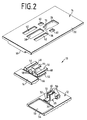
- FIGS. 1 and 2 show the individual parts of an embodiment of a switch 10 for a device for personal use, for example for an electric shaver or a toothbrush shown in perspective. This embodiment is shown in section in the following FIGS. 3a to 3c in the assembled state and is explained in more detail below with reference to these figures.
- the switch 10 consists of a device switch 12 and a locking switch 14, which are slidably received in a support member 16.
- the support member 16 is part of a housing, not shown in the drawing, in which an electrically operable drive part is provided for operating the device.
- the supporting part 16 consists of a rectangular recess or recess 24 provided in the housing wall of the device and used to hold the device switch 12 and the locking switch 14, with a front limiting part 18 and a rear limiting part 20.
- a rectangular opening 26 is provided on the axis of symmetry of the supporting part 16, which is used to receive an L-shaped locking part 28, the leg 32 of which runs parallel to the underside 30 of the supporting part 16 and has a knob 34 at the end, which in the operating position of the device switch 12 counteracts abuts a web 36 of the support member 16.
- the web 36 delimits the left end of the opening 26 and the right end of an elongated hole opening 38, which serves to receive the knob 34 when the device switch 12 has been adjusted to the left according to FIG. 3c. In this position, the knob 34 provided on the leg 32 of the locking part 28 is located in the elongated hole opening 38.
- the L-shaped locking part 44 is formed on the locking switch 14 and extends through the elongated hole opening 38 adjoining the web 36. Parallel to the elongated hole opening 38 run two further slot openings 40, the are designed to be somewhat shorter than the elongated hole opening 38.
- the elongated hole openings 40 serve to receive two locking parts 46, which are also L-shaped and are each provided with knobs 48 at the ends.
- the locking parts 28 and 46 are advantageously designed to be resilient, so that they slide slightly upwards as they slide along on the underside 30 of the supporting part 16 until the knobs 34 and 48 snap into corresponding recesses.
- the device switch 12 is provided with a recess 50 into which the front end part 52 of the locking switch 14 can be pushed until the end face 66 of the locking switch 14 comes to rest against the end face 54 of the device switch 12.
- the locking part 28 of the device switch 12 has on both sides of the locking part 28 small hooks 56 which rest on the underside 30 of the supporting part 16 and which are firmly connected to the device switch 12.
- the hooks 56 also extend through the opening 26 and secure the locking part 28 against slipping out of the opening 26. If the device switch 12 with the locking part 28 is to be removed from the opening 26, only the two opposite hook parts 56 need to be pressed a little, so that the upper part of the hook part no longer bears against the underside 30 of the supporting part 16. The device switch 12 can then easily be pulled out of the opening 26.
- two hooks 58 are also arranged on the locking switch 14, which according to. 3a to 3c the locking switch 14th secure on the support member 16 and allow adjustment of the locking switch 14.
- the two locking parts 46 of the locking switch 14, which run parallel to one another, engage with their knobs 48 in recesses or recesses 60 when the locking switch according to FIG. 3b has been moved completely to the right.
- the device switch 12 is in its exhibition and is secured by the locking switch 14 against unintentional adjustment.
- the locking switch 14 and the device switch 12 assume a central position in which the knobs 48 of the legs 46 of the locking switch 14 and the rib 34 of the leg 32 of the device switch rest resiliently on the web 36.
- the device switch 12 acc. Fig. 3b completely to the right in a switch-off position, the device switch 12 rests with its grip part against an edge 62 of the limiting part 20 of the support part 16, so that a further adjustment of the device switch 12 to the right is prevented.
- the knob 34 is moved behind the web 36 and engages in the opening 26 due to the spring-elastic design of the locking part 28.
- the locking switch 14 can now be moved to the right, the L-shaped locking part 44 moving over the L-shaped locking part 28 pushes and thus prevents the knob 34 can move out of the opening 26. This ensures that the device switch 12 which is in exhibition cannot move to the left into an operating position, since the knob 34 blocked by the L-shaped locking part 44 of the locking switch 14 only comes to rest against the edge 70 of the web 36.
- By pushing the locking part 44 onto the locking part 28 a non-positive connection between the two locking parts is also obtained, which is caused by the friction between the underside of the locking part 44 and the surface of the locking part 28.
- the locking part 44 can also be provided with a knob, also not shown in the drawing, which can snap into recesses provided on the surface of the locking part 28. This additionally creates a jamming or wedging of the locking part 44 with the locking part 28.
- the device switch 12 and the locking switch 14 by positive locking elements and non-positive locking elements after taking the position acc. Fig. 3b secured. Since the device switch 12 and the locking switch 14 can be moved and pushed into one plane, the overall height of the switching element 10 is greatly reduced compared to conventional switching elements.
- the locking switch 14 takes the position acc. 3b, the knobs 48 of the locking parts 46 also snap into the recesses 60 of the supporting part 16. This provides a positive connection between the locking switch 14 and the support member 16.
- the locking switch 14 must first be moved all the way to the left until it abuts the limiting part 18, the knobs 48 being moved out of the cutouts 60 and being transferred via the web 36 into the slot openings 40 .
- the L-shaped locking part 44 releases the locking part 28 of the device switch 12.
- the knob 34 slides on the underside 30 of the supporting part 16 via the web 36 into the elongated hole opening 38 until the end face 54 of the device switch 12 comes into contact with an end face 66 of the locking switch 14. From this operating position shown in Fig. 3c, the device switch 12 can lack a blocking effect by the L-shaped locking part 44 at any time moved back to the right to the switch-off position or then moved back to the switch-on position.
- the device switch 12 is in its switched-off position, the knob 34 resting against an edge 70 of the web 36 delimiting the opening 26.
- the contact element 72 provided between the walls 61 is arranged at a distance from another contact element 74 provided in the housing of the device, so that the circuit of the electrical drive of the device is interrupted.
- an L-shaped locking part 44 is pushed over the front end of the locking part 28 and prevents the knobs 34 from moving over the edge 70 and the web 36 on the underside 30 of the supporting part 16 or the housing. The locking part 44 thus prevents an adjustment of the device switch 12 into an operating position.
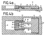
- the locking switch and device switch are equipped with U-shaped locking brackets which can be moved into one another and thus serve to secure the device switch.
- the device switch 12 is also slidably received in a supporting part 16 or a housing and is equipped with a U-shaped locking bracket 80, which consists of two parallel spring-elastic legs 82 and 84, which have knobs at the ends 34 have.
- a U-shaped locking bracket 80 which consists of two parallel spring-elastic legs 82 and 84, which have knobs at the ends 34 have.
- the two legs 82 and 84 can no longer be moved apart, so that an adjustment of the device switch 12 due to the legs 82 and 84 resting on the fixed bolt 37 is excluded.
- the device switch 12 can only be adjusted again after the locking switch 14 has been adjusted to the left, so that the knobs 34 can then be moved past the bolt 37 again.
- an opening 87 passing through the partition wall and a depression 24 delimiting the sliding path of the device switch 12 and the locking switch 14 are provided in the partition wall 16.
- a U-shaped locking bracket 79 consisting of two resilient legs 82 and 84, which are provided with knobs 35 on the end.
- the legs 82 and 84 with the knobs 35 grip the bolt 86, which is formed on the device switch 12 as a component thereof.
- a U-shaped locking bracket 81 protruding into the opening 87, the legs 83 and 85 of which engage around the legs 82 and 84 in order to trigger a spreading movement of the legs 82 and 84, which can be triggered by the bolt 86 which can be displaced via the device switch 12 , to prevent.
- two locking lugs 90 and 92 are provided on the locking switch 14, which engage in locking grooves 94, 96 or 97, 98 provided in the side walls 100 and 102 of the opening 87, depending on the respective switching position of the locking switch 14.
- the locking lugs 90 and 92 are preferably formed on two spring-elastic hooks 58 which, for easy assembly and mounting of the locking part 14 in the opening 87 of the partition 16 - as can be seen in FIG. 5d - on the locking part 14 partially under the partition 16 are provided, the dimensions of the locking lugs 90, 92 being such that, by utilizing the resilient properties of the hooks 58, the locking part 14 can be displaced until the holding part of the locking part 14 is maintained by means of the hooks 58 at the same time.
- resiliently designed hooks 56 are also formed, which partially engage under the partition wall 16 for guiding and holding the device switch 12.
- the device switch 12 is in its switched-off position, in which it is held against unintentional sliding movements by the locking switch 14.
- the locking lugs 90 and 92 of the locking switch are in engagement with corresponding locking grooves 94 and 96.
- the legs 83 and 85 of the U-shaped locking bracket of the locking switch 14 encompass the spring-elastic legs 82 and 84 of the U-shaped locking bracket 79 and thus prevent a spreading movement this leg 82 and 84, which is essential for a release or displacement of the device switch 12, the bolt 86 located between the legs 82 and 84 is secured against displacement by the legs 82 and 84 and the knobs 35 formed thereon.
- the locking switch 14 By moving the locking switch 14 to the left into the locking position shown in FIG. 5c, in which the locking lugs 90 and 92 are in engagement with the locking grooves 97 and 98, the locking of the legs 82 and 84 by the legs 83 and 85 is released.
- the device switch 12 can also be moved to the left into an operating position, the pin 86 acting on the knobs 35 and, using the spring-elastic properties of the legs 82 and 84, causing these legs to spread, in the course of which the pin 86 between the knobs 35 5c, to assume the switch position shown in FIG. 5c, which corresponds to the operating position of the device switch 12, in which the electrical circuit of an electric drive is closed by a contact element, which is not shown in FIGS. 5a-5c but is provided on the device switch 12.
- the device switch 12 is held by the spring 86 of the resilient legs 82, 84 and the knobs 35 integrally formed thereon, both in the operating position and in the switch-off position and is made use of the spring-elastic properties of the legs 82, 84 from the respective switch position into the other switch position transferable.
- the device switch 12 can be ascertained by sliding the legs 83 and 85 of the U-shaped locking bracket 81 of the locking switch 14 onto the legs 82 and 84 of the partition 16 against any sliding movement acting on the device switch 12.
- a recess 24 is provided in the partition 16, in which the device switch 12 and the locking switch 14 are slidably mounted.
- the device switch 12 is slidably fastened by means of four hooks 56, which are guided through corresponding elongated holes 104 provided in the partition 16 and reach under the partition 16.
- Two further elongated holes 106 provided in the partition 16, which are penetrated by corresponding hooks 58 formed on the locking switch 14 and which engage under the partition 16, serve for the sliding fastening of the locking switch 14 on the partition 16.
- the locking switch 14 consists of a U-shaped bracket 81 which can be inserted between the legs 82 and 84, the resiliently designed legs 83 and 85 of which are provided with knobs 35 which are arranged on the longitudinal side walls 108 and 110 abut as well as an actuating element 114 which is guided through an opening 112 provided in the device switch 12, the opening 112 being designed in such a way that an unimpeded displacement of the locking switch 14 via the actuating element 114 is ensured.
- the device switch 12 is in its exhibition, in which it is secured by the locking switch 14 inserted between the legs 82 and 84.
- the locking switch 14 By shifting the locking switch 14 to the left, the resilient legs 83 and 85 springing with the knobs 35 over projections 116 provided on the side walls 108 and 110, the locking switch 14 is brought from the shown blocking position into a release position in which the knobs 35 are are in contact with the locking positions 120.
- the device switch 12 thus unlocked can now be transferred from the illustrated switch-off position to the operating position due to the spring-elastic legs 82 and 84, which is reached after the projections 118 have slid around by the knobs 34 provided on the legs 82 and 84.
- the device switch 12 is provided with a contact element, not shown, which closes the electrical circuit of an electric drive in the operating position of the device switch.
Landscapes
- Switch Cases, Indication, And Locking (AREA)
- Slide Switches (AREA)
- Emergency Protection Circuit Devices (AREA)
- Push-Button Switches (AREA)
- Dry Shavers And Clippers (AREA)
- Keying Circuit Devices (AREA)
- Electrophonic Musical Instruments (AREA)
Claims (15)
- Commutateur pour un appareil d'utilisation personnelle, comprenant un commutateur d'appareil (12) afin d'enclencher et de déclencher une partie d'entraînement mue de manière électrique et prévue dans un boîtier d'appareil, ainsi qu'un commutateur d'arrêt (14) qui peut être déplacé dans le trajet de commutation du commutateur d'appareil (12) caractérisé en ce que le commutateur d'arrêt (14) et le commutateur d'appareil (12) sont déplaçables de manière rectiligne et respectivement dans la même direction lors de l'enclenchement ou du déclenchement, en ce que le commutateur d'appareil (12) et/ou le commutateur d'arrêt (14) comportent des éléments à blocage de forme et/ou de force, qui sont en coulissement l'un dans l'autre, ou qui peuvent être amenés en engagement l'un dans l'autre, afin d'assurer le commutateur d'appareil (12) dans la position de déclenchement au moyen du commutateur d'arrêt (14), et en ce que le commutateur d'appareil (12) ainsi que le commutateur d'arrêt (14) sont reçus sur une partie porteuse (16) du boîtier de l'appareil.
- Commutateur selon la revendication 1, caractérisé en ce que le commutateur d'appareil (12) comprend au moins un élément à blocage de forme (28, 80, 86) qui est retenu dans des positions de commutation prédéterminées au moyen d'au moins un élément d'encliquetage (36, 37, 79, 118) prévu sur la pièce porteuse (16).
- Commutateur selon la revendication 1, caractérisé en ce que le commutateur d'arrêt (14) comporte des pièces d'arrêt (46, 83, 85, 90, 92) qui peuvent être déplacées dans des positions d'encliquetage (40, 60, 94, 96, 97, 98, 119, 120) prévues sur la pièce porteuse (16).
- Commutateur selon la revendication 2, caractérisé en ce que l'élément à blocage de forme (28) du commutateur d'appareil (12) consiste en une pièce d'arrêt en forme de L et élastique à la manière d'un ressort, comprenant un bouton (34) formé sur son bras (32).
- Commutateur selon la revendication 2, caractérisé en ce que l'élément à blocage de forme (80) du commutateur d'appareil (12) est réalisé sous la forme d'un écrier d'arrêt en forme de U, avec un bouton (34) formé sur chacun de ses bras (82, 84), ceux-ci étant réalisés de manière élastique.
- Commutateur selon la revendication 2, caractérisé en ce que l'élément à blocage de forme (86) du commutateur d'appareil (12) est formé sous la forme d'une tige sur le commutateur d'appareil (12).
- Commutateur selon la revendication 2, caractérisé en ce que l'élément d'encliquetage (36) est constitué par un voile situé entre deux ouvertures allongées (26, 38) prévues dans la pièce porteuse (16).
- Commutateur selon la revendication 2, caractérisé en ce que l'élément d'encliquetage (37) est formé sous la forme d'une tige sur la pièce porteuse (16).
- Commutateur selon la revendication 2, caractérisé en ce que l'élément d'encliquetage (79) est constitué par un étrier d'arrêt en forme de U et formé sur la paroi de séparation (16), un bouton (35) étant formé sur chacun de ses bras (82, 84) élastiques à la manière de ressorts.
- Commutateur selon l'une des revendications précédentes 4, 5 et 9, caractérisé en ce que le commutateur d'arrêt (14) comprend au moins un élément à blocage de force (44, 81) qui peut être déplacé dans le trajet d'élasticité des éléments (28, 80) à blocage de forme du commutateur d'appareil (12).
- Commutateur selon la revendication 9 ou 10, caractérisé en ce que le commutateur d'arrêt (14) comprend au moins un élément à blocage de force (81), qui peut être déplacé dans le trajet d'élasticité des bras élastiques (82, 84) de l'élément d'encliquetage (79) de la paroi de séparation (16).
- Commutateur selon la revendication 10, caractérisé en ce que l'élément à blocage de force (44) est réalisé sous la forme d'une pièce d'arrêt en forme de L, qui peut être déplacée dans la position de déclenchement du commutateur d'appareil (12) sur l'élément à blocage de forme (28) de ce dernier.
- Commutateur selon la revendication 10, caractérisé en ce que l'élément à blocage de force (81) est réalisé sous la forme d'un étrier d'arrêt en forme de U, dont les bras (83, 85) peuvent être déplacés, dans la position de déclenchement du commutateur d'appareil (12), sur les bras (82, 84) de l'élément à blocage de forme (80) du commutateur d'appareil (12).
- Commutateur selon la revendication 10, caractérisé en ce que l'élément à blocage de force (81) est réalisé sous la forme d'un étrier d'arrêt en forme de U, dont la base (123) qui relie les bras (83 et 85) peut être déplacée entre les bras (82, 84) de l'élément à blocage de forme (80).
- Commutateur selon l'une des revendications précédentes, caractérisé en ce que dans l'une au moins des parois latérales longitudinales (110, 108) de la pièce porteuse (16), les positions d'encliquetage (121, 122, 119, 120) sont formées au moyen de saillies (118, 115, 116) en forme.
Applications Claiming Priority (2)
| Application Number | Priority Date | Filing Date | Title |
|---|---|---|---|
| DE3727921 | 1987-08-21 | ||
| DE3727921A DE3727921C1 (de) | 1987-08-21 | 1987-08-21 | Schalter zur Ein- und Ausschaltung eines elektrisch betreibbaren Antriebsteiles eines Geraetes |
Publications (3)
| Publication Number | Publication Date |
|---|---|
| EP0307601A2 EP0307601A2 (fr) | 1989-03-22 |
| EP0307601A3 EP0307601A3 (en) | 1990-08-22 |
| EP0307601B1 true EP0307601B1 (fr) | 1995-02-15 |
Family
ID=6334198
Family Applications (1)
| Application Number | Title | Priority Date | Filing Date |
|---|---|---|---|
| EP88112523A Expired - Lifetime EP0307601B1 (fr) | 1987-08-21 | 1988-08-02 | Interrupteur d'appareil avec protection d'enclenchement |
Country Status (6)
| Country | Link |
|---|---|
| US (1) | US4882458A (fr) |
| EP (1) | EP0307601B1 (fr) |
| JP (2) | JPS6481132A (fr) |
| AT (1) | ATE118642T1 (fr) |
| DE (2) | DE3727921C1 (fr) |
| HK (1) | HK92796A (fr) |
Cited By (2)
| Publication number | Priority date | Publication date | Assignee | Title |
|---|---|---|---|---|
| DE19745714A1 (de) * | 1997-10-16 | 1999-05-06 | Braun Gmbh | Schalter für ein Gerät des persönlichen Bedarfs |
| DE10310163A1 (de) * | 2003-03-08 | 2004-09-16 | Braun Gmbh | Schiebeschalter |
Families Citing this family (25)
| Publication number | Priority date | Publication date | Assignee | Title |
|---|---|---|---|---|
| US5268674A (en) * | 1992-01-31 | 1993-12-07 | Apple Computer, Inc. | Mechanically latching mouse button |
| DE4229756A1 (de) * | 1992-09-05 | 1994-03-10 | Abb Patent Gmbh | Elektrisches Schaltgerät |
| DE4236516C2 (de) * | 1992-10-29 | 2003-06-18 | Ascom Audiosys Ag Flamatt | Fernbedienung mit verschiebbarer Abdeckklappe |
| US5383875A (en) * | 1994-05-31 | 1995-01-24 | Zimmer, Inc. | Safety device for a powered surgical instrument |
| DE4439905A1 (de) * | 1994-11-08 | 1996-05-09 | Teves Gmbh Alfred | Getriebeschalter mit Schaltsperre durch Schiebetaste |
| US5738206A (en) * | 1997-04-16 | 1998-04-14 | Leviton Manufacturing Co., Inc. | Child resistant switch lock |
| DE19911317A1 (de) * | 1999-03-13 | 2000-09-28 | Braun Gmbh | Verfahren zum Betreiben eines elektrischen Geräts sowie elektrisches Gerät mit Einschaltschutz |
| DE29920439U1 (de) | 1999-11-22 | 2000-02-03 | Schreiber, Raimund, 76307 Karlsbad | Fernbediengerät |
| KR100384315B1 (ko) * | 2000-12-18 | 2003-05-16 | 대부기공주식회사 | 자동차용 시트레일의 로킹시스템 |
| US20020152576A1 (en) * | 2001-04-20 | 2002-10-24 | Pro-Team, Inc. An Idaho Corporation | Method and apparatus for improved use, maintenance and management of floor maintenance equipment |
| WO2002090865A2 (fr) * | 2001-05-07 | 2002-11-14 | Vito Cellini | Baton |
| US7040559B2 (en) | 2004-04-02 | 2006-05-09 | Fellowes Inc. | Shredder with lock for on/off switch |
| DE102005002421A1 (de) * | 2005-01-18 | 2006-07-27 | Leopold Kostal Gmbh & Co. Kg | Betätigungseinrichtung zur Ansteuerung eines fremdkraftbetätigten Aggregats zum Öffnen und Schließen einer Karosserieöffnung eines Kraftfahrzeugs |
| JP4774919B2 (ja) * | 2005-10-31 | 2011-09-21 | アイシン精機株式会社 | 車両用シートスライド装置 |
| CN2915259Y (zh) | 2006-07-14 | 2007-06-27 | 上海震旦办公设备有限公司 | 碎纸机触碰安全装置 |
| US8008812B2 (en) | 2006-07-14 | 2011-08-30 | Aurora Office Equipment Co., Ltd. | Paper shredder control system responsive to touch-sensitive element |
| CN201239643Y (zh) | 2008-08-06 | 2009-05-20 | 上海震旦办公设备有限公司 | 不择纸的全自动碎纸机 |
| CN201244502Y (zh) | 2008-08-19 | 2009-05-27 | 上海震旦办公设备有限公司 | 自动碎纸机可剃钉结构 |
| CN101543800A (zh) | 2009-05-07 | 2009-09-30 | 上海震旦办公设备有限公司 | 碎纸机防卡纸保护装置 |
| US8723468B2 (en) | 2011-04-28 | 2014-05-13 | Aurora Office Equipment Co., Ltd. | Cooled motor |
| US8708260B2 (en) | 2011-08-08 | 2014-04-29 | Aurora Office Equipment Co., Ltd. | Depowered standby paper shredder and method |
| DE102011084464B4 (de) | 2011-10-13 | 2013-09-05 | Dewert Antriebs- Und Systemtechnik Gmbh | Mechanisch sperrbare Kabelfernbedienung |
| JP6167304B2 (ja) * | 2014-08-18 | 2017-07-26 | パナソニックIpマネジメント株式会社 | ハンドブレンダ |
| GB2573289B (en) * | 2018-04-30 | 2021-06-30 | Lister Shearing Equip Ltd | Improvement in or Relating to Clippers |
| US12502760B2 (en) | 2021-02-25 | 2025-12-23 | Black & Decker Inc. | Compact powered wrench |
Family Cites Families (13)
| Publication number | Priority date | Publication date | Assignee | Title |
|---|---|---|---|---|
| DE1947573U (de) * | 1966-07-20 | 1966-10-13 | Wietek & Co Elektrotechn | Schiebeschalter, insbesondere fuer taschenleuchten. |
| US3839614A (en) * | 1973-03-16 | 1974-10-01 | Schick Inc | Appliance control system |
| US4112271A (en) * | 1976-12-20 | 1978-09-05 | Sperry Rand Corporation | Counter device associated with switch actuator of electrical shaver to determine battery recharging and use |
| DD139689A1 (de) * | 1977-10-25 | 1980-01-16 | Walter Hammerschmidt | Batterieraumabdeckungsverriegelung und schalter fuer batteriebetriebene spielzeuge |
| DE2850120A1 (de) * | 1977-11-21 | 1979-05-23 | Black & Decker Mfg Co | Schalter-betaetigungseinrichtung |
| US4180712A (en) * | 1978-07-13 | 1979-12-25 | Switchcraft, Inc. | Slide switch |
| JPS6047250B2 (ja) * | 1979-02-05 | 1985-10-21 | 住友化学工業株式会社 | 1,6,8↓−デカトリエンの製造方法 |
| FR2515349A1 (fr) * | 1981-10-26 | 1983-04-29 | Commissariat Energie Atomique | Dispositif de prelevement d'echantillons liquides et banc de prelevement utilisant un tel dispositif |
| US4504707A (en) * | 1982-03-15 | 1985-03-12 | Kyushu Hitachi Maxell, Ltd. | Push-button switch locking device for use in electric appliance |
| GB2118886B (en) * | 1982-03-15 | 1985-07-17 | Hitachi Maxell | Electric shaver |
| JPS59144924A (ja) * | 1983-02-08 | 1984-08-20 | Canon Inc | 電子機器 |
| DE3315643C2 (de) * | 1983-04-29 | 1985-08-08 | Braun Ag, 6000 Frankfurt | Automatischer Einschaltschutz |
| JPS6071A (ja) * | 1983-06-15 | 1985-01-05 | Matsushita Electric Works Ltd | 電池による負荷駆動装置 |
-
1987
- 1987-08-21 DE DE3727921A patent/DE3727921C1/de not_active Expired
-
1988
- 1988-08-02 EP EP88112523A patent/EP0307601B1/fr not_active Expired - Lifetime
- 1988-08-02 AT AT88112523T patent/ATE118642T1/de not_active IP Right Cessation
- 1988-08-02 DE DE3853031T patent/DE3853031D1/de not_active Expired - Fee Related
- 1988-08-02 US US07/227,150 patent/US4882458A/en not_active Expired - Lifetime
- 1988-08-19 JP JP63206240A patent/JPS6481132A/ja active Pending
-
1996
- 1996-05-30 HK HK92796A patent/HK92796A/xx not_active IP Right Cessation
-
1997
- 1997-06-23 JP JP1997005379U patent/JP2606915Y2/ja not_active Expired - Lifetime
Cited By (3)
| Publication number | Priority date | Publication date | Assignee | Title |
|---|---|---|---|---|
| DE19745714A1 (de) * | 1997-10-16 | 1999-05-06 | Braun Gmbh | Schalter für ein Gerät des persönlichen Bedarfs |
| DE19745714C2 (de) * | 1997-10-16 | 2000-04-27 | Braun Gmbh | Schiebeschalter für ein Gerät des persönlichen Bedarfs |
| DE10310163A1 (de) * | 2003-03-08 | 2004-09-16 | Braun Gmbh | Schiebeschalter |
Also Published As
| Publication number | Publication date |
|---|---|
| JPH10116U (ja) | 1998-05-06 |
| JP2606915Y2 (ja) | 2001-02-19 |
| US4882458A (en) | 1989-11-21 |
| DE3727921C1 (de) | 1989-01-05 |
| JPS6481132A (en) | 1989-03-27 |
| HK92796A (en) | 1996-06-07 |
| EP0307601A3 (en) | 1990-08-22 |
| ATE118642T1 (de) | 1995-03-15 |
| DE3853031D1 (de) | 1995-03-23 |
| EP0307601A2 (fr) | 1989-03-22 |
Similar Documents
| Publication | Publication Date | Title |
|---|---|---|
| DE3727921C1 (de) | Schalter zur Ein- und Ausschaltung eines elektrisch betreibbaren Antriebsteiles eines Geraetes | |
| EP0392200B1 (fr) | Dispositif de verrouillage à sécurité pour une porte d'appareil électrique | |
| DE4025382A1 (de) | Verbessertes schloss mit zuschlagwirkung mit auswurffeder | |
| DE1129587B (de) | Elektrischer Schnappschalter mit zwei unter Zugfederspannung am Stoessel gehalterten Kontaktarmen | |
| DE4202214A1 (de) | Elektrischer schalter | |
| DE2850120A1 (de) | Schalter-betaetigungseinrichtung | |
| DE2028499C3 (de) | Elektrische Schaltvorrichtung | |
| DE8424056U1 (de) | Schraubenlose Anschlußklemme für elektrische Geräte, insbesondere für Installationsgeräte | |
| DE2509566C2 (de) | Elektrischer befehlsschalter | |
| DE2559861B1 (de) | Verriegelbarer Drucktastenschalter | |
| DE10216209C1 (de) | Berührungsschutzvorrichtung mit Längsschieber für eine elektrische Steckdose | |
| DE3485796T2 (de) | Adaptierungsvorrichtung zur seitlichen betaetigung eines schiebeschalters. | |
| DE2144756C3 (de) | Fernbetätigungsvorrichtung, insbesondere für Kraftfahrzeugtürschlösser | |
| DE2607186C2 (de) | Drucktastenschalter | |
| DE4336931C2 (de) | In eine elektrische Schutzkontaktsteckdose nachträglich einsetzbare Kinderschutzsicherung | |
| DE68908003T2 (de) | Vorrichtung zum Manövrieren des Klemmechanismus modularer elektrischer Geräte. | |
| DE29502987U1 (de) | Ausklinkbares Schnappschloß | |
| DE2904646C2 (de) | Drucktastenschalter | |
| DE3107440A1 (de) | Elektrischer schalter, insbesondere zur anordnung im schalthebelende eines lenkstockschalters | |
| DE3707491C2 (fr) | ||
| DE2702555C2 (de) | Drucktasten-Schalterblock | |
| DE10211814C1 (de) | Schutzkontaktsteckdose mit im Steckdosensockel integrierter Berührungsschutzvorrichtung | |
| EP0464174B1 (fr) | Boucle de ceinture pour systemes de retenue de ceinture | |
| DE3324253A1 (de) | Tastenschalter | |
| EP0302249A1 (fr) | Disjoncteur à maximum de courant commandé par un bouton-poussoir |
Legal Events
| Date | Code | Title | Description |
|---|---|---|---|
| PUAI | Public reference made under article 153(3) epc to a published international application that has entered the european phase |
Free format text: ORIGINAL CODE: 0009012 |
|
| AK | Designated contracting states |
Kind code of ref document: A2 Designated state(s): AT CH DE FR GB LI NL |
|
| PUAL | Search report despatched |
Free format text: ORIGINAL CODE: 0009013 |
|
| AK | Designated contracting states |
Kind code of ref document: A3 Designated state(s): AT CH DE FR GB LI NL |
|
| 17P | Request for examination filed |
Effective date: 19900911 |
|
| 17Q | First examination report despatched |
Effective date: 19920717 |
|
| GRAA | (expected) grant |
Free format text: ORIGINAL CODE: 0009210 |
|
| AK | Designated contracting states |
Kind code of ref document: B1 Designated state(s): AT CH DE FR GB LI NL |
|
| REF | Corresponds to: |
Ref document number: 118642 Country of ref document: AT Date of ref document: 19950315 Kind code of ref document: T |
|
| GBT | Gb: translation of ep patent filed (gb section 77(6)(a)/1977) |
Effective date: 19950203 |
|
| REF | Corresponds to: |
Ref document number: 3853031 Country of ref document: DE Date of ref document: 19950323 |
|
| ET | Fr: translation filed | ||
| RAP2 | Party data changed (patent owner data changed or rights of a patent transferred) |
Owner name: BRAUN AKTIENGESELLSCHAFT |
|
| REG | Reference to a national code |
Ref country code: CH Ref legal event code: PFA Free format text: BRAUN AKTIENGESELLSCHAFT TRANSFER- BRAUN AKTIENGESELLSCHAFT |
|
| NLT2 | Nl: modifications (of names), taken from the european patent patent bulletin |
Owner name: BRAUN AKTIENGESELLSCHAFT |
|
| PLBE | No opposition filed within time limit |
Free format text: ORIGINAL CODE: 0009261 |
|
| STAA | Information on the status of an ep patent application or granted ep patent |
Free format text: STATUS: NO OPPOSITION FILED WITHIN TIME LIMIT |
|
| 26N | No opposition filed | ||
| REG | Reference to a national code |
Ref country code: FR Ref legal event code: CD Ref country code: FR Ref legal event code: CA |
|
| REG | Reference to a national code |
Ref country code: CH Ref legal event code: PFA Free format text: BRAUN AKTIENGESELLSCHAFT TRANSFER- BRAUN AKTIENGESELLSCHAFT;BRAUN GMBH Ref country code: CH Ref legal event code: NV Representative=s name: BOSSHARD & LUCHS PATENTANWAELTE;LUCHS & PARTNER PA |
|
| REG | Reference to a national code |
Ref country code: GB Ref legal event code: IF02 |
|
| PGFP | Annual fee paid to national office [announced via postgrant information from national office to epo] |
Ref country code: GB Payment date: 20020722 Year of fee payment: 15 |
|
| PGFP | Annual fee paid to national office [announced via postgrant information from national office to epo] |
Ref country code: FR Payment date: 20020820 Year of fee payment: 15 |
|
| PGFP | Annual fee paid to national office [announced via postgrant information from national office to epo] |
Ref country code: CH Payment date: 20020903 Year of fee payment: 15 |
|
| PG25 | Lapsed in a contracting state [announced via postgrant information from national office to epo] |
Ref country code: GB Free format text: LAPSE BECAUSE OF NON-PAYMENT OF DUE FEES Effective date: 20030802 |
|
| PGFP | Annual fee paid to national office [announced via postgrant information from national office to epo] |
Ref country code: NL Payment date: 20030819 Year of fee payment: 16 |
|
| PGFP | Annual fee paid to national office [announced via postgrant information from national office to epo] |
Ref country code: AT Payment date: 20030820 Year of fee payment: 16 |
|
| PG25 | Lapsed in a contracting state [announced via postgrant information from national office to epo] |
Ref country code: LI Free format text: LAPSE BECAUSE OF NON-PAYMENT OF DUE FEES Effective date: 20030831 Ref country code: CH Free format text: LAPSE BECAUSE OF NON-PAYMENT OF DUE FEES Effective date: 20030831 |
|
| GBPC | Gb: european patent ceased through non-payment of renewal fee |
Effective date: 20030802 |
|
| REG | Reference to a national code |
Ref country code: CH Ref legal event code: PL |
|
| PG25 | Lapsed in a contracting state [announced via postgrant information from national office to epo] |
Ref country code: FR Free format text: LAPSE BECAUSE OF NON-PAYMENT OF DUE FEES Effective date: 20040430 |
|
| REG | Reference to a national code |
Ref country code: FR Ref legal event code: ST |
|
| PGFP | Annual fee paid to national office [announced via postgrant information from national office to epo] |
Ref country code: DE Payment date: 20040731 Year of fee payment: 17 |
|
| PG25 | Lapsed in a contracting state [announced via postgrant information from national office to epo] |
Ref country code: AT Free format text: LAPSE BECAUSE OF NON-PAYMENT OF DUE FEES Effective date: 20040802 |
|
| PG25 | Lapsed in a contracting state [announced via postgrant information from national office to epo] |
Ref country code: NL Free format text: LAPSE BECAUSE OF NON-PAYMENT OF DUE FEES Effective date: 20050301 |
|
| NLV4 | Nl: lapsed or anulled due to non-payment of the annual fee |
Effective date: 20050301 |
|
| PG25 | Lapsed in a contracting state [announced via postgrant information from national office to epo] |
Ref country code: DE Free format text: LAPSE BECAUSE OF NON-PAYMENT OF DUE FEES Effective date: 20060301 |