EP0307610B1 - Joint déformable pour couvrir la distance entre le bord d'une ouverture d'un bâtiment et l'arrière d'un véhicule touchant le bâtiment - Google Patents
Joint déformable pour couvrir la distance entre le bord d'une ouverture d'un bâtiment et l'arrière d'un véhicule touchant le bâtiment Download PDFInfo
- Publication number
- EP0307610B1 EP0307610B1 EP88112752A EP88112752A EP0307610B1 EP 0307610 B1 EP0307610 B1 EP 0307610B1 EP 88112752 A EP88112752 A EP 88112752A EP 88112752 A EP88112752 A EP 88112752A EP 0307610 B1 EP0307610 B1 EP 0307610B1
- Authority
- EP
- European Patent Office
- Prior art keywords
- web
- building
- seal according
- tear
- arrangement
- Prior art date
- Legal status (The legal status is an assumption and is not a legal conclusion. Google has not performed a legal analysis and makes no representation as to the accuracy of the status listed.)
- Expired - Lifetime
Links
- 238000007789 sealing Methods 0.000 title claims 2
- 230000001012 protector Effects 0.000 abstract 2
- 239000004744 fabric Substances 0.000 abstract 1
- 239000002184 metal Substances 0.000 description 5
- 239000000463 material Substances 0.000 description 4
- 238000005299 abrasion Methods 0.000 description 1
- 230000002411 adverse Effects 0.000 description 1
- 238000010586 diagram Methods 0.000 description 1
Images
Classifications
-
- B—PERFORMING OPERATIONS; TRANSPORTING
- B65—CONVEYING; PACKING; STORING; HANDLING THIN OR FILAMENTARY MATERIAL
- B65G—TRANSPORT OR STORAGE DEVICES, e.g. CONVEYORS FOR LOADING OR TIPPING, SHOP CONVEYOR SYSTEMS OR PNEUMATIC TUBE CONVEYORS
- B65G69/00—Auxiliary measures taken, or devices used, in connection with loading or unloading
- B65G69/008—Dock- or bumper-seals
Definitions
- the invention relates to a deformable seal according to the preamble of the 1st protection claim.
- the invention has for its object to improve the aforementioned deformable seals so that the Wear protection elements can be replaced quickly without having to disassemble the cross part of the seal.
- the invention aims at a seal in which any elements can be used for wear protection without having to fear an adverse influence, for example wrinkling of the cross part.
- the wear protection elements are arranged and stored independently of the cross section, and for their attachment, e.g. uses a screw connection that allows easy replacement of the elements.
- the tab-like, apron-like wear elements can also be directly detachably connected to the web, e.g. be releasably inserted in an undercut groove of the web.
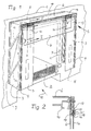
- a building 1 has an opening 2 to which vehicles can be approached for loading and unloading.
- These coverings made of a flexible, waterproof material or the like provide a connection to an apron with a vertical strip 5 from the building 1 both sides of the opening 2 and an upper cross part 6.
- the parts 5 and 6 are made of a flexible material, for example from a waterproof film or the like.
- the opening 2 is enclosed by a U-shaped frame with vertical legs 7 and an upper web 8. These metal parts are firmly connected to the building 1. They serve to fasten the edges of the covering 3, 4. The edges of the covering 3, 4 facing away from the building are firmly connected to another U-shaped frame. Its vertical legs are 9, the web is 10. Handlebars 11 pivotable against spring force serve to hold and guide the front frame (9, 10).
- the handlebars 11 are pivoted when a vehicle is moved towards the opening 2 in the direction of the arrow 12. It touches the strips 5 and the cross member 6, whereby the frame 9, 10 can give way by pivoting the handlebars 11 upward, namely deforming the covering 3, 4. It is understood that the strips 5 and the cross member 6 adapt to the shape of the vehicle and bring about the desired seal.
- the cross member 6 is arranged in such a way that it covers the upper ends 13 of the strips 5, which are only fastened to their lateral edges, specifically on the legs 9.
- the cross member 6 is however only fastened to the web 10.
- the tabs 14 are arranged at a short distance in front of the cross member 6 and are also detachably connected to the web 10 by the upper edge. Accordingly, the tab 14 can be replaced quickly without having to remove the remaining parts of the seal.
- the upper edge 15 of the tabs 14 engages in a slot 16 at the bottom of a metal profile 17 which is screwed onto the end face of the web 10.
- the upper edge 15 is also provided with a plurality of holes 17 'for receiving mostly spherical locking bodies 18 which engage in corresponding extensions 19 of the slot 16 to secure the tab 14 against falling out.
- the slot 16 with the extension 19 _ forming a narrow longitudinal groove in the profile 17 _ has the advantage that the tab 14 can be removed by pulling it out of the slot 16 and re-installed by threading it. Interchangeability is therefore possible by removing the metal profile 17, but also by pulling out the tab 14. The latter option is mainly used.
Landscapes
- Engineering & Computer Science (AREA)
- Mechanical Engineering (AREA)
- Seal Device For Vehicle (AREA)
- Professional, Industrial, Or Sporting Protective Garments (AREA)
- Specific Sealing Or Ventilating Devices For Doors And Windows (AREA)
Claims (8)
Priority Applications (1)
| Application Number | Priority Date | Filing Date | Title |
|---|---|---|---|
| AT88112752T ATE63288T1 (de) | 1987-09-10 | 1988-08-05 | Verformbare dichtung des spaltes zwischen dem rand einer gebaeudeoeffnung und dem heck eines an diese herangefahrenen fahrzeuges. |
Applications Claiming Priority (2)
| Application Number | Priority Date | Filing Date | Title |
|---|---|---|---|
| DE3730317 | 1987-09-10 | ||
| DE3730317 | 1987-09-10 |
Publications (2)
| Publication Number | Publication Date |
|---|---|
| EP0307610A1 EP0307610A1 (fr) | 1989-03-22 |
| EP0307610B1 true EP0307610B1 (fr) | 1991-05-08 |
Family
ID=6335649
Family Applications (1)
| Application Number | Title | Priority Date | Filing Date |
|---|---|---|---|
| EP88112752A Expired - Lifetime EP0307610B1 (fr) | 1987-09-10 | 1988-08-05 | Joint déformable pour couvrir la distance entre le bord d'une ouverture d'un bâtiment et l'arrière d'un véhicule touchant le bâtiment |
Country Status (3)
| Country | Link |
|---|---|
| EP (1) | EP0307610B1 (fr) |
| AT (1) | ATE63288T1 (fr) |
| DE (2) | DE8717557U1 (fr) |
Families Citing this family (6)
| Publication number | Priority date | Publication date | Assignee | Title |
|---|---|---|---|---|
| DE4111367A1 (de) * | 1990-09-25 | 1992-03-26 | Alten K | Verformbare dichtung des spaltes zwischen dem rand einer gebaeudeoeffnung und dem heck eines an diese herangefahrenen fahrzeuges |
| DE4243297C1 (de) * | 1992-12-21 | 1994-02-03 | Alten Geraetebau Gmbh | Dichtung des Spaltes zwischen dem Rand einer Gebäudeöffnung und dem Heck eines andockenden Fahrzeuges |
| NL1007283C2 (nl) * | 1997-10-15 | 1999-04-19 | Stertil Bv | Inrichting voor het afschermen van een loodsingang. |
| ES2238907B1 (es) * | 2003-07-25 | 2006-07-01 | Grupo Combursa, S.L. | Abrigo para muelles de carga/ descarga de vehiculos. |
| DE102010022057A1 (de) * | 2010-01-31 | 2011-08-04 | Nani Verladetechnik GmbH & Co. KG, 39365 | Torabdichtung mit Dichtung eines LKW-Türspaltes |
| CN107250009B (zh) * | 2014-09-11 | 2019-10-01 | 瑞泰控股公司 | 用于密封或遮蔽装卸站台处的车辆的天气屏障设备 |
Family Cites Families (2)
| Publication number | Priority date | Publication date | Assignee | Title |
|---|---|---|---|---|
| US3403489A (en) * | 1966-12-12 | 1968-10-01 | Dubuque Awning & Tent Co | Loading dock shelters |
| DE2927233A1 (de) * | 1979-07-05 | 1981-01-15 | Huebner Gummi & Kunststoff | Ladetorabdichtung |
-
1987
- 1987-09-10 DE DE8717557U patent/DE8717557U1/de not_active Expired
-
1988
- 1988-08-05 EP EP88112752A patent/EP0307610B1/fr not_active Expired - Lifetime
- 1988-08-05 DE DE8888112752T patent/DE3862726D1/de not_active Expired - Lifetime
- 1988-08-05 AT AT88112752T patent/ATE63288T1/de not_active IP Right Cessation
Also Published As
| Publication number | Publication date |
|---|---|
| DE3862726D1 (de) | 1991-06-13 |
| DE8717557U1 (de) | 1989-03-23 |
| ATE63288T1 (de) | 1991-05-15 |
| EP0307610A1 (fr) | 1989-03-22 |
Similar Documents
| Publication | Publication Date | Title |
|---|---|---|
| DE3740913B4 (de) | Dichtung für eine Kraftfahrzeugtür | |
| EP0226711B1 (fr) | Fraiseuse de neige | |
| DE3101821C2 (de) | Randeinfassung für einen Sonnendacheinsatz eines Kraftfahrzeugs | |
| DE4111367A1 (de) | Verformbare dichtung des spaltes zwischen dem rand einer gebaeudeoeffnung und dem heck eines an diese herangefahrenen fahrzeuges | |
| DE7535971U (de) | Abstreifeinrichtung für Gleitbahnen an Werkzeugmaschinen | |
| DE10038200B4 (de) | Fensterdichtung zur Anbringung an einer Kraftfahrzeugtüre | |
| DE3146908C2 (de) | Randspaltabdichtung an einem Kraftfahrzeugschiebedach | |
| DE19732348C2 (de) | Vorrichtung zum Entfernen von Eis-, Schnee- und Wasseransammlungen auf Planen | |
| EP0307610A1 (fr) | Joint déformable pour couvrir la distance entre le bord d'une ouverture d'un bâtiment et l'arrière d'un véhicule touchant le bâtiment | |
| DE3207795A1 (de) | Dicht- und abschlussleiste | |
| EP1295814A1 (fr) | Dispositif de vidange pour récipients contenant des produits pulvérulents | |
| DE9018011U1 (de) | Verformbare Dichtung des Spaltes zwischen dem Rand einer Gebäudeöffnung und dem Heck eines an diese herangefahrenen Fahrzeuges | |
| EP0097219B1 (fr) | Poignée-barre ou analogue pour véhicules | |
| DE3107988A1 (de) | Aussenrueckspiegel fuer kraftfahrzeuge | |
| DE1780686B1 (de) | Loesbare halterung fuer einen windabweiser | |
| DE3618696A1 (de) | Entwaesserungsrinne | |
| DE3309898C2 (fr) | ||
| DE2032345C3 (de) | Spannspriegel für den Himmelbezug an Schiebedeckeln von starren Schiebedächern | |
| DE9107819U1 (de) | Torabdichtung | |
| EP0641731B1 (fr) | Joint pour couvrir la fente entre le bord d'une ouverture d'un bâtiment et l'arrière d'un véhicule | |
| DE20017839U1 (de) | Profil für den oberen Rand eines Schwimmbeckens und derart gestaltetes Schwimmbecken | |
| DE8523104U1 (de) | Vorrichtung zum Aufhängen von einen Vorhang bildenden Lamellen | |
| DE69306987T2 (de) | Warndreieckhalterung eines Fahrzeuges | |
| EP1676973B1 (fr) | Profilé de porte entre le battant d'une porte et la paroi d'un compartiment | |
| DE2403078A1 (de) | Behaelter |
Legal Events
| Date | Code | Title | Description |
|---|---|---|---|
| PUAI | Public reference made under article 153(3) epc to a published international application that has entered the european phase |
Free format text: ORIGINAL CODE: 0009012 |
|
| AK | Designated contracting states |
Kind code of ref document: A1 Designated state(s): AT BE CH DE ES FR GB GR IT LI LU NL SE |
|
| 17P | Request for examination filed |
Effective date: 19890207 |
|
| 17Q | First examination report despatched |
Effective date: 19901026 |
|
| GRAA | (expected) grant |
Free format text: ORIGINAL CODE: 0009210 |
|
| AK | Designated contracting states |
Kind code of ref document: B1 Designated state(s): AT BE CH DE ES FR GB GR IT LI LU NL SE |
|
| PG25 | Lapsed in a contracting state [announced via postgrant information from national office to epo] |
Ref country code: SE Effective date: 19910508 Ref country code: NL Effective date: 19910508 Ref country code: GB Effective date: 19910508 Ref country code: FR Effective date: 19910508 Ref country code: ES Free format text: THE PATENT HAS BEEN ANNULLED BY A DECISION OF A NATIONAL AUTHORITY Effective date: 19910508 Ref country code: BE Effective date: 19910508 Ref country code: IT Free format text: LAPSE BECAUSE OF FAILURE TO SUBMIT A TRANSLATION OF THE DESCRIPTION OR TO PAY THE FEE WITHIN THE PRE;WARNING: LAPSES OF ITALIAN PATENTS WITH EFFECTIVE DATE BEFORE 2007 MAY HAVE OCCURRED AT ANY TIME BEFORE 2007. THE CORRECT EFFECTIVE DATE MAY BE DIFFERENT FROM THE ONE RECORDED.SCRIBED TIME-LIMIT Effective date: 19910508 Ref country code: GR Free format text: LAPSE BECAUSE OF FAILURE TO SUBMIT A TRANSLATION OF THE DESCRIPTION OR TO PAY THE FEE WITHIN THE PRESCRIBED TIME-LIMIT Effective date: 19910508 |
|
| REF | Corresponds to: |
Ref document number: 63288 Country of ref document: AT Date of ref document: 19910515 Kind code of ref document: T |
|
| REF | Corresponds to: |
Ref document number: 3862726 Country of ref document: DE Date of ref document: 19910613 |
|
| PG25 | Lapsed in a contracting state [announced via postgrant information from national office to epo] |
Ref country code: AT Effective date: 19910805 |
|
| PG25 | Lapsed in a contracting state [announced via postgrant information from national office to epo] |
Ref country code: LI Effective date: 19910831 Ref country code: CH Effective date: 19910831 Ref country code: LU Free format text: LAPSE BECAUSE OF NON-PAYMENT OF DUE FEES Effective date: 19910831 |
|
| EN | Fr: translation not filed | ||
| NLV1 | Nl: lapsed or annulled due to failure to fulfill the requirements of art. 29p and 29m of the patents act | ||
| GBV | Gb: ep patent (uk) treated as always having been void in accordance with gb section 77(7)/1977 [no translation filed] | ||
| PLBE | No opposition filed within time limit |
Free format text: ORIGINAL CODE: 0009261 |
|
| STAA | Information on the status of an ep patent application or granted ep patent |
Free format text: STATUS: NO OPPOSITION FILED WITHIN TIME LIMIT |
|
| 26N | No opposition filed | ||
| REG | Reference to a national code |
Ref country code: CH Ref legal event code: PL |
|
| PGFP | Annual fee paid to national office [announced via postgrant information from national office to epo] |
Ref country code: DE Payment date: 19921026 Year of fee payment: 5 |
|
| PG25 | Lapsed in a contracting state [announced via postgrant information from national office to epo] |
Ref country code: DE Effective date: 19940503 |