EP0307645B1 - Dispositif manipulateur destiné à un système de montage et comportant un élément porteur et un élément coulissant - Google Patents
Dispositif manipulateur destiné à un système de montage et comportant un élément porteur et un élément coulissant Download PDFInfo
- Publication number
- EP0307645B1 EP0307645B1 EP88113467A EP88113467A EP0307645B1 EP 0307645 B1 EP0307645 B1 EP 0307645B1 EP 88113467 A EP88113467 A EP 88113467A EP 88113467 A EP88113467 A EP 88113467A EP 0307645 B1 EP0307645 B1 EP 0307645B1
- Authority
- EP
- European Patent Office
- Prior art keywords
- carrier element
- constructed
- housing
- slide unit
- side walls
- Prior art date
- Legal status (The legal status is an assumption and is not a legal conclusion. Google has not performed a legal analysis and makes no representation as to the accuracy of the status listed.)
- Expired - Lifetime
Links
Images

Classifications
-
- B—PERFORMING OPERATIONS; TRANSPORTING
- B23—MACHINE TOOLS; METAL-WORKING NOT OTHERWISE PROVIDED FOR
- B23Q—DETAILS, COMPONENTS, OR ACCESSORIES FOR MACHINE TOOLS, e.g. ARRANGEMENTS FOR COPYING OR CONTROLLING; MACHINE TOOLS IN GENERAL CHARACTERISED BY THE CONSTRUCTION OF PARTICULAR DETAILS OR COMPONENTS; COMBINATIONS OR ASSOCIATIONS OF METAL-WORKING MACHINES, NOT DIRECTED TO A PARTICULAR RESULT
- B23Q1/00—Members which are comprised in the general build-up of a form of machine, particularly relatively large fixed members
- B23Q1/25—Movable or adjustable work or tool supports
- B23Q1/44—Movable or adjustable work or tool supports using particular mechanisms
- B23Q1/56—Movable or adjustable work or tool supports using particular mechanisms with sliding pairs only, the sliding pairs being the first two elements of the mechanism
- B23Q1/58—Movable or adjustable work or tool supports using particular mechanisms with sliding pairs only, the sliding pairs being the first two elements of the mechanism a single sliding pair
-
- B—PERFORMING OPERATIONS; TRANSPORTING
- B23—MACHINE TOOLS; METAL-WORKING NOT OTHERWISE PROVIDED FOR
- B23Q—DETAILS, COMPONENTS, OR ACCESSORIES FOR MACHINE TOOLS, e.g. ARRANGEMENTS FOR COPYING OR CONTROLLING; MACHINE TOOLS IN GENERAL CHARACTERISED BY THE CONSTRUCTION OF PARTICULAR DETAILS OR COMPONENTS; COMBINATIONS OR ASSOCIATIONS OF METAL-WORKING MACHINES, NOT DIRECTED TO A PARTICULAR RESULT
- B23Q1/00—Members which are comprised in the general build-up of a form of machine, particularly relatively large fixed members
- B23Q1/0009—Energy-transferring means or control lines for movable machine parts; Control panels or boxes; Control parts
-
- B—PERFORMING OPERATIONS; TRANSPORTING
- B23—MACHINE TOOLS; METAL-WORKING NOT OTHERWISE PROVIDED FOR
- B23Q—DETAILS, COMPONENTS, OR ACCESSORIES FOR MACHINE TOOLS, e.g. ARRANGEMENTS FOR COPYING OR CONTROLLING; MACHINE TOOLS IN GENERAL CHARACTERISED BY THE CONSTRUCTION OF PARTICULAR DETAILS OR COMPONENTS; COMBINATIONS OR ASSOCIATIONS OF METAL-WORKING MACHINES, NOT DIRECTED TO A PARTICULAR RESULT
- B23Q1/00—Members which are comprised in the general build-up of a form of machine, particularly relatively large fixed members
- B23Q1/01—Frames, beds, pillars or like members; Arrangement of ways
- B23Q1/015—Frames, beds, pillars
-
- B—PERFORMING OPERATIONS; TRANSPORTING
- B25—HAND TOOLS; PORTABLE POWER-DRIVEN TOOLS; MANIPULATORS
- B25J—MANIPULATORS; CHAMBERS PROVIDED WITH MANIPULATION DEVICES
- B25J18/00—Arms
- B25J18/02—Arms extensible
-
- B—PERFORMING OPERATIONS; TRANSPORTING
- B25—HAND TOOLS; PORTABLE POWER-DRIVEN TOOLS; MANIPULATORS
- B25J—MANIPULATORS; CHAMBERS PROVIDED WITH MANIPULATION DEVICES
- B25J9/00—Program-controlled manipulators
- B25J9/0009—Constructional details, e.g. manipulator supports, bases
- B25J9/0012—Constructional details, e.g. manipulator supports, bases making use of synthetic construction materials, e.g. plastics, composites
-
- B—PERFORMING OPERATIONS; TRANSPORTING
- B25—HAND TOOLS; PORTABLE POWER-DRIVEN TOOLS; MANIPULATORS
- B25J—MANIPULATORS; CHAMBERS PROVIDED WITH MANIPULATION DEVICES
- B25J9/00—Program-controlled manipulators
- B25J9/02—Program-controlled manipulators characterised by movement of the arms, e.g. cartesian coordinate type
- B25J9/023—Cartesian coordinate type
- B25J9/026—Gantry-type
Definitions
- the invention relates to a device for a mounting system for handling technology, consisting of a support element designed as a guideway and at least one slide unit arranged linearly adjustable thereon, which slide unit is operatively connected electrically / pneumatically or electrically / hydraulically to an energy and signal source via a cable drag link and is designed as a mounting and support element for further peripherals to be actuated accordingly (see, for example, GB-A-2176168).
- Correspondingly designed mounting systems are known for the automation of any, for example, signal-dependent, predetermined movements and handling sequences, in which a slide unit designed to accommodate one or more working elements is / can be adjusted linearly on or on a correspondingly designed carrier element.
- the energy or electrical control signals required for the individual movement and / or further handling processes are essentially provided via a cable drag chain or the like of the slide unit, for example arranged on the side of the carrier element, and by means of further, largely exposed flexible cables or lines to the correspondingly assigned handling member (gripper or the like).
- the carrier element forms a self-contained arrangement, protected against external interference, by means of appropriately designed side walls or protective elements arranged detachably on the carrier element, in which outwardly directed webs of the slide unit are each designed in a correspondingly designed manner, the length of the beam is arranged in the longitudinal direction and is formed in the manner of a slot and is essentially guided.
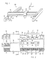
- FIG. 1 shows a mounting system of handling technology in modular design, schematically shown as a general overview, known per se and designated in its entirety with 100, with two parallel and spaced-apart guide tracks 90 and 93, on which a third essentially guide track 94 oriented transversely thereto is arranged.
- the two first guideways 90 and 93 extend along a first coordinate axis X and the third guideway 94 along a second coordinate axis Y.
- At least one slide unit 91, 92 or 95 is arranged on each of the guideways 90, 93 and 94, wherein in Embodiment shown, the two carriage units 91, 92 is designed for a translation of the third guideway 94 and carriage unit 95 operatively connected to it in a manner not shown in the arrow direction X '.
- the carriage unit 95 is designed for independent translation in the direction of the arrow Y '.
- the carriage unit 95 which can be moved in the direction of the arrow Y 'can be designed to receive and fasten a linear unit (not shown in more detail) which can be moved in the direction of the arrow Z, and a gripper member (not shown) or the like can also be arranged on the linear unit.
- the gripper member not shown, can can also be arranged and attached directly to the slide unit 95.
- the guideways 90, 93 and 94 shown in FIG. 1, for example, as a largely complete assembly system 100 with the slide units 91, 92 and 95 correspondingly arranged thereon or laterally for the respective movement and / or handling sequences can also be in accordance with the requirements placed on the assembly system can be used as a single unit.
- the guide track 94 has a fixed support element 10 which extends over the entire length and is designed for the linear adjustment movement of the slide unit 95 and a cable drag link, for example a drag chain 150, which is operatively connected to the slide unit 95.
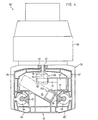
- the carrier element 10 shown in FIG. 3 in profile cross section and on a larger scale has a first, lower floor 12, to which two approximately vertical side walls 13, 14 are arranged at a distance from one another.
- a formed in the upper area on one side wall 13 upper floor 16 is formed inclined downwards with respect to the lower floor 12 and with an approximately perpendicular to this wall piece 16 'essentially connected to the other, vertical side wall 14.
- the bottom 16 with the wall piece 16 'and a section 16' arranged at a parallel distance from the bottom 16 together form a guide track 15 extending over the entire length of the carrier element 10.
- the pocket-like guide track 15 is schematic for receiving the one in FIG only partially shown drag chain 150 formed.
- the guideway 15 correspondingly arranged in the carrier element 10 achieves a space-saving inclined position which is protected against external interference and optimal guidance of the drag chain 150 in the carrier element 10.
- the two bottom parts 17, 19 are arranged by correspondingly arranged cross struts 17 ', 19 'are stabilized.
- a second floor 11 is provided in the lower area of the carrier element 10, which extends into the outer area of the side walls 13, 14 but is not connected to the walls 13, 14, so that between the first floor 12 and the second bottom 11 pocket-like chambers 11 ', 11 ⁇ are formed, which preferably extend over the entire length of the carrier element 10 and whose use will be described later.
- a sloping bottom 16 to the second, lower floor 11 reaching, and spaced from the side walls 13, 14 arranged intermediate walls 13 ', 14' are provided.
- Carrier element 10 comprising 18 and 20 forms a rigid cell construction and is preferably designed as a one-piece profile body and, for example, made of light metal, preferably of aluminum, in an extrusion process known per se.
- a guide element 25, 26 is arranged on each side of the carrier element 10, which likewise extends over the entire length of the carrier element 10 in a manner not shown.
- the individual, arranged below the upper floors 17, 19 and in the front area, for example as a round profile 25 ', 26' formed guide element 25, 26 is by means not shown releasably attached to the side walls 13, 14 of the carrier element 10 and essentially serves for displaceable mounting and linear guidance of the slide unit 95.
- a toothed rack 30 is arranged, which also extends over the entire length of the carrier element 10 and is detachably fastened to the bottom part 19 by means not shown.
- the slide unit 95 arranged on the carrier element 10 and essentially in operative connection with the toothed rack 30 fastened to the base 19 comprises, as shown in FIG. 3, a head piece 35 which largely encompasses the carrier element 10 and is U-shaped in profile cross section and has two parallel legs 37, 38 and an intermediate piece 40 connecting the two legs 37 and 38.
- the head piece 35 which essentially serves as a holder for a drive unit designated as a whole by 45, has on the inside at least one with corresponding sliding elements on each of the legs 37, 38 (Not shown) provided bearing part 36 and 39.
- the individual, claw-like encompassing the respective guide element 25 or 26 bearing part 36 or 39 is by means of screws 34, 34 ', as shown on one side in a partially cut-open state, on the legs 37, 38 of the head piece 35 releasably attached.
- two, preferably but several (not shown) spaced apart, designed as slide bearings (ball, needle bearings or the like) bearing parts 36, 39 are provided on the legs 37, 38 of the head piece 35, which bearing parts 36, 39 ensure an optimal, that is, a smooth adjustment movement of the entire slide unit 95 in the direction of the arrow Y '(FIGS. 1 and 2).
- the bearing parts 36, 39 can also be formed in one piece and extend in the direction of movement Y '(Fig. 2) over the entire length (not shown) of the head piece 35.
- the intermediate piece 40 of the U-shaped head piece 35 is designed to receive and fasten the drive unit 45.
- the drive unit 45 essentially comprises a housing 50, which is designed to accommodate and mount one or, as shown schematically in FIG. 2, a plurality of drives 60, 61, 62 and 63.
- the drives 60 to 63 which are preferably designed as direct current motors, are arranged axially parallel in series one behind the other and are mounted in a manner not shown in the side walls 51 and 52 of the housing 50.
- each individual motor 60, 61, 62 and 63 is by means of a shaft, not shown and shown in more detail, and a gear pinion 60 ', 61', 62 'and 63' arranged on the shaft with the rack 30 connected. Furthermore, one can see in Fig. 2 a schematically shown and stored in the housing 50 in a manner not shown way measuring device 64, which is also via a pinion 64 'with the rack 30 in engagement.
- the housing 50 provided for the storage of the parts 60 to 64 and approximately U-shaped in profile cross section has, as shown in FIG. 3 in a partially cut-open state, the two walls 51, 52 connecting one another and designed as an upper cover Intermediate piece 53 is a section which is oriented in the longitudinal direction (FIG. 2) of housing 50 and is formed in a T-shape from a web 55 with flange 54 and a further web 56 is formed on one end face (FIG. 3).
- the housing 50 for example in the form of a one-piece aluminum casting, is arranged with the flange 54 in a recess 42 provided in the head piece 35 and oriented in the longitudinal direction and, as shown in FIG. 3 in a partially cut-open state, fastened by means of screws 41, 41 ', so that the head piece 35 with which the drive unit 45 comprising the parts 50, 60 to 64 forms a structural unit.
- FIG. 2 is arranged at one end of the housing 50 in a schematically illustrated and in a manner not shown attached to the flange 54 distributor element 70, which has a first connector designated 71 for connecting a hydraulic or pneumatic line and a second connector 72 for connecting an electrical line.
- the individual lines (not shown) for the energy and signal transmission are essentially supplied to the housing 50 or the drive units 45 via the drag chain 150.
- protective elements 75, 75 'and 80, 80' are provided, which are detachably attached to the carrier element 10 by means not shown, preferably by a clamp connection.
- the protective elements 80, 80 'arranged in the lower area on both sides of the carrier element 10 are clamped into the pocket-like chambers 11', 11 '.
- the protective elements 75, 75 'and 80, 80' extending over the entire length of the carrier element 10 are arranged with respect to one another and fastened to the carrier element 10 in such a way that on the one hand the gap 76 for the web 55 of the housing 50 and on the other hand on both sides of the carrier element 10 a gap 77 and 78, respectively, for the bearing parts 36, 39 arranged and fastened on the head piece 35, so that the slide unit 95, as indicated in FIG. 1 and FIG. 2 with arrow direction Y ', in the longitudinal direction of the Guide track 94 is freely movable.
- the formed as a profile hollow body and divided by several spaced apart, not specified ribs and webs in the interior protective elements 75, 75 'and 80, 80' are made of plastic, for example, and form a stable unit in itself.
- the chambers formed in the protective elements 75, 75 'and 80, 80' formed due to the ribs and webs can be foamed with suitable plastic to dampen any vibrations that occur, thereby achieving additional stability of the individual protective elements.
- Fig. 4 shows a variant shown in section and in its entirety with 95 'designated carriage unit and you can see the designated 10 support member with the protective elements 75, 75' and 80, 80 'arranged on both sides, which is arranged in the pocket 15 and mounted drag chain 150 as well as the head piece 35 mounted essentially on the guide elements 25, 26 with the parts 36, 39.
- FIG Drive unit differs from the first variant according to FIG Drive unit a single DC motor 85 arranged on the outside of the head piece 35 and operatively connected to it by means not shown, is provided.
- the motor 85 has a shaft 84 which penetrates the intermediate piece 40 of the head piece 35, which is shown partially cut away and provided with a correspondingly designed and arranged bore 45.
- a toothed pinion 83 is arranged on the shaft 84 in the inner region of the head piece 35 and is mounted in a schematically illustrated housing 68.
- the toothed pinion 83 which is operatively connected to the shaft 84, engages with a toothed rack 31, the toothed rack 31 being arranged on a block-shaped rail 32 fastened to the bottom 19 of the carrier element 10 by means not shown.
- the two parts 31 and 32 which extend over the entire length of the carrier element 10, can also be formed in one piece and releasably attached to the bottom 19 by means not shown.
- the lines, not shown, which are fed to the housing 50 or 68 from the drag chain 150, are preferably connected to the end face of the respective housing.
- the drag chain 150 is also preferably operatively connected to the housing.
- This special, essentially integrated energy and signal supply prevents unintentional interference in the moving elements.
- the energy and signal supply to a peripheral device can largely take place by direct connection to the block-shaped distributor element 70, as a result of which flexible lines susceptible to faults are no longer required.
Landscapes
- Engineering & Computer Science (AREA)
- Mechanical Engineering (AREA)
- Robotics (AREA)
- Electric Cable Arrangement Between Relatively Moving Parts (AREA)
- Automatic Assembly (AREA)
- Manipulator (AREA)
- Current-Collector Devices For Electrically Propelled Vehicles (AREA)
- Apparatuses And Processes For Manufacturing Resistors (AREA)
- Automobile Manufacture Line, Endless Track Vehicle, Trailer (AREA)
Claims (14)
Priority Applications (1)
| Application Number | Priority Date | Filing Date | Title |
|---|---|---|---|
| AT88113467T ATE68391T1 (de) | 1987-08-27 | 1988-08-19 | Vorrichtung fuer ein montagesystem der handhabungstechnik, bestehend aus einem traegerelement und einer schlitteneinheit. |
Applications Claiming Priority (2)
| Application Number | Priority Date | Filing Date | Title |
|---|---|---|---|
| CH332087 | 1987-08-27 | ||
| CH3320/87 | 1987-08-27 |
Publications (2)
| Publication Number | Publication Date |
|---|---|
| EP0307645A1 EP0307645A1 (fr) | 1989-03-22 |
| EP0307645B1 true EP0307645B1 (fr) | 1991-10-16 |
Family
ID=4253439
Family Applications (1)
| Application Number | Title | Priority Date | Filing Date |
|---|---|---|---|
| EP88113467A Expired - Lifetime EP0307645B1 (fr) | 1987-08-27 | 1988-08-19 | Dispositif manipulateur destiné à un système de montage et comportant un élément porteur et un élément coulissant |
Country Status (9)
| Country | Link |
|---|---|
| US (1) | US4885996A (fr) |
| EP (1) | EP0307645B1 (fr) |
| JP (1) | JPS6464741A (fr) |
| AT (1) | ATE68391T1 (fr) |
| CA (1) | CA1304320C (fr) |
| DE (1) | DE3865613D1 (fr) |
| ES (1) | ES2027739T3 (fr) |
| GR (1) | GR3003480T3 (fr) |
| SU (1) | SU1716961A3 (fr) |
Families Citing this family (13)
| Publication number | Priority date | Publication date | Assignee | Title |
|---|---|---|---|---|
| DE3910692A1 (de) * | 1989-04-03 | 1990-10-31 | Ief Werner Gmbh | Linear- und dreheinheit |
| FR2651904A1 (fr) * | 1989-09-14 | 1991-03-15 | Andromac Technologies | Installation de distribution d'articles tels que des cassettes video. |
| DE4111885C2 (de) * | 1991-04-09 | 1994-10-27 | Mannesmann Ag | Handhabungsvorrichtung, die aus Modulbaugruppen gebildet ist |
| FR2692830A1 (fr) * | 1992-06-25 | 1993-12-31 | Kitenic Systeme Numerique Sarl | Module linéaire de guidage pour la translation et la manutention de toutes pièces et accessoires. |
| JPH09503894A (ja) * | 1994-08-03 | 1997-04-15 | モトローラ・インコーポレイテッド | 高度通信システム・アーキテクチャ |
| DE19631661C2 (de) * | 1996-08-05 | 2000-05-25 | Homag Maschinenbau Ag | Bearbeitungsmaschine |
| DE19631630C2 (de) * | 1996-08-05 | 2001-05-31 | Homag Maschinenbau Ag | Bearbeitungsmaschine mit einer Saugspanneinrichtung |
| US6129027A (en) * | 1996-08-05 | 2000-10-10 | Shomag Maschinenbau Ag | Processing machine |
| DE19833125A1 (de) * | 1998-07-23 | 2000-01-27 | Actech Gmbh Adv Casting Tech | Flächenportalsystem mit linearen Direktantrieben |
| JP2003343677A (ja) * | 2002-05-27 | 2003-12-03 | Smc Corp | 電動アクチュエータ |
| JP4816662B2 (ja) * | 2008-03-06 | 2011-11-16 | 株式会社安川電機 | リニア軸のケーブル処理機構およびそれを用いた基板搬送装置 |
| JP2010267806A (ja) * | 2009-05-14 | 2010-11-25 | Nikon Corp | ステージ装置、ケーブル保持装置、露光装置、及びデバイス製造方法 |
| CN119461040B (zh) * | 2025-01-16 | 2025-04-22 | 山西四建集团有限公司 | 大跨度异形网格结构整体顶升装置及顶升方法 |
Family Cites Families (5)
| Publication number | Priority date | Publication date | Assignee | Title |
|---|---|---|---|---|
| GB1069667A (en) * | 1964-11-21 | 1967-05-24 | B St I P Konstrukcji Stalowych | Crab-supporting beam for an overhead travelling crane |
| US3833774A (en) * | 1972-09-19 | 1974-09-03 | Dresser Ind | Cable support for overhead crane trolleys |
| LU78204A1 (de) * | 1977-09-29 | 1979-05-25 | Bleichert Foerderanlagen Gmbh | Einschienenfoerderanlage |
| SE439968B (sv) * | 1982-10-19 | 1985-07-08 | Ulf Kenneth Folke Fasth | Stelldon |
| JPS61284379A (ja) * | 1985-06-06 | 1986-12-15 | 本田技研工業株式会社 | ロボツト装置 |
-
1988
- 1988-08-12 CA CA000574686A patent/CA1304320C/fr not_active Expired - Lifetime
- 1988-08-15 US US07/232,628 patent/US4885996A/en not_active Expired - Fee Related
- 1988-08-19 AT AT88113467T patent/ATE68391T1/de active
- 1988-08-19 DE DE8888113467T patent/DE3865613D1/de not_active Expired - Lifetime
- 1988-08-19 ES ES198888113467T patent/ES2027739T3/es not_active Expired - Lifetime
- 1988-08-19 EP EP88113467A patent/EP0307645B1/fr not_active Expired - Lifetime
- 1988-08-24 SU SU884356316A patent/SU1716961A3/ru active
- 1988-08-26 JP JP63210873A patent/JPS6464741A/ja active Pending
-
1991
- 1991-12-31 GR GR91402248T patent/GR3003480T3/el unknown
Also Published As
| Publication number | Publication date |
|---|---|
| EP0307645A1 (fr) | 1989-03-22 |
| DE3865613D1 (de) | 1991-11-21 |
| ATE68391T1 (de) | 1991-11-15 |
| ES2027739T3 (es) | 1992-06-16 |
| JPS6464741A (en) | 1989-03-10 |
| CA1304320C (fr) | 1992-06-30 |
| US4885996A (en) | 1989-12-12 |
| SU1716961A3 (ru) | 1992-02-28 |
| GR3003480T3 (en) | 1993-02-17 |
Similar Documents
| Publication | Publication Date | Title |
|---|---|---|
| DE3720175C2 (fr) | ||
| EP0170802B1 (fr) | Dispositif de guidage pour deux pièces de machine supportées et entraînées longitudinalement l'une contre l'autre | |
| DE3336496C2 (fr) | ||
| DE3724321B4 (de) | Zweischnitt-Bandsägemaschine | |
| EP0307645A1 (fr) | Dispositif manipulateur destiné à un système de montage et comportant un élément porteur et un élément coulissant | |
| EP3040296A1 (fr) | Systeme de transfert/montage modulaire | |
| EP1321225A2 (fr) | Installation pour l'usinage avec au moins un chemin de transport et une pluralité de stations de travail | |
| EP2762270A1 (fr) | Machine de production | |
| DE9414501U1 (de) | Bearbeitungsmaschine mit relativverschiebbaren Drehvorrichtungen | |
| DE4090853B4 (de) | Schnitteilstück-Transportvorrichtung für eine Schneidemaschine | |
| EP0893201A2 (fr) | Système téléscopique | |
| EP0283548A1 (fr) | Dispositif de commande linéaire | |
| DE102005061193A1 (de) | Handhabungsverfahren und -vorrichtung, insbesondere an einer Spritzgussmaschine | |
| WO2000054930A2 (fr) | Machine-outil | |
| DE4142060A1 (de) | Geradefuehrungseinheit mit einem synchronisierten waelzlagerkaefig | |
| DE8707584U1 (de) | Vorrichtung zum Aufnehmen, Transportieren, Ablegen und/oder Positionieren von Werkstücken | |
| DE8807313U1 (de) | Linearantrieb für Handhabungsaufgaben mit zwei Schlitten | |
| EP0623533A1 (fr) | Procédé et dispositif de transport pour transporter des porte-pièces | |
| DE3508841C2 (fr) | ||
| DE102017110931A1 (de) | Bearbeitungszentrum | |
| DE3914008A1 (de) | Vorrichtung zum herstellen und bearbeiten von werkstuecken beliebiger geometrie | |
| DE69601360T2 (de) | Festhängung von werkzeugköpfen für numerisch gesteuerte arbeitsstation | |
| DE4301216A1 (de) | Vorrichtung zur Führung der Werkstücke bei einer automatischen Holzbearbeitungsmaschine | |
| DE19853408B4 (de) | Anlage zur Bearbeitung und/oder Montage von Bauteilen | |
| DE102010019678A1 (de) | Linearantrieb mit Auslegerarm |
Legal Events
| Date | Code | Title | Description |
|---|---|---|---|
| PUAI | Public reference made under article 153(3) epc to a published international application that has entered the european phase |
Free format text: ORIGINAL CODE: 0009012 |
|
| AK | Designated contracting states |
Kind code of ref document: A1 Designated state(s): AT BE CH DE ES FR GB GR IT LI LU NL SE |
|
| 17P | Request for examination filed |
Effective date: 19890619 |
|
| 17Q | First examination report despatched |
Effective date: 19901218 |
|
| GRAA | (expected) grant |
Free format text: ORIGINAL CODE: 0009210 |
|
| AK | Designated contracting states |
Kind code of ref document: B1 Designated state(s): AT BE CH DE ES FR GB GR IT LI LU NL SE |
|
| REF | Corresponds to: |
Ref document number: 68391 Country of ref document: AT Date of ref document: 19911115 Kind code of ref document: T |
|
| REF | Corresponds to: |
Ref document number: 3865613 Country of ref document: DE Date of ref document: 19911121 |
|
| ITF | It: translation for a ep patent filed | ||
| ET | Fr: translation filed | ||
| GBT | Gb: translation of ep patent filed (gb section 77(6)(a)/1977) | ||
| REG | Reference to a national code |
Ref country code: ES Ref legal event code: FG2A Ref document number: 2027739 Country of ref document: ES Kind code of ref document: T3 |
|
| PG25 | Lapsed in a contracting state [announced via postgrant information from national office to epo] |
Ref country code: GB Effective date: 19920819 Ref country code: AT Effective date: 19920819 |
|
| PG25 | Lapsed in a contracting state [announced via postgrant information from national office to epo] |
Ref country code: SE Effective date: 19920820 Ref country code: ES Free format text: LAPSE BECAUSE OF THE APPLICANT RENOUNCES Effective date: 19920820 |
|
| PLBE | No opposition filed within time limit |
Free format text: ORIGINAL CODE: 0009261 |
|
| STAA | Information on the status of an ep patent application or granted ep patent |
Free format text: STATUS: NO OPPOSITION FILED WITHIN TIME LIMIT |
|
| PG25 | Lapsed in a contracting state [announced via postgrant information from national office to epo] |
Ref country code: LU Free format text: LAPSE BECAUSE OF NON-PAYMENT OF DUE FEES Effective date: 19920831 Ref country code: BE Effective date: 19920831 |
|
| 26N | No opposition filed | ||
| REG | Reference to a national code |
Ref country code: GR Ref legal event code: FG4A Free format text: 3003480 |
|
| PGFP | Annual fee paid to national office [announced via postgrant information from national office to epo] |
Ref country code: CH Payment date: 19921126 Year of fee payment: 5 |
|
| PGFP | Annual fee paid to national office [announced via postgrant information from national office to epo] |
Ref country code: GR Payment date: 19930127 Year of fee payment: 5 |
|
| BERE | Be: lapsed |
Owner name: HIRSCHMANN GREGORY C. Effective date: 19920831 |
|
| PG25 | Lapsed in a contracting state [announced via postgrant information from national office to epo] |
Ref country code: NL Effective date: 19930301 |
|
| NLV4 | Nl: lapsed or anulled due to non-payment of the annual fee | ||
| GBPC | Gb: european patent ceased through non-payment of renewal fee |
Effective date: 19920819 |
|
| PG25 | Lapsed in a contracting state [announced via postgrant information from national office to epo] |
Ref country code: FR Effective date: 19930430 |
|
| PG25 | Lapsed in a contracting state [announced via postgrant information from national office to epo] |
Ref country code: DE Effective date: 19930501 |
|
| REG | Reference to a national code |
Ref country code: FR Ref legal event code: ST |
|
| PG25 | Lapsed in a contracting state [announced via postgrant information from national office to epo] |
Ref country code: GR Free format text: THE PATENT HAS BEEN ANNULLED BY A DECISION OF A NATIONAL AUTHORITY Effective date: 19940228 |
|
| REG | Reference to a national code |
Ref country code: CH Ref legal event code: PL |
|
| REG | Reference to a national code |
Ref country code: GR Ref legal event code: MM2A Free format text: 3003480 |
|
| EUG | Se: european patent has lapsed |
Ref document number: 88113467.0 Effective date: 19930307 |
|
| REG | Reference to a national code |
Ref country code: ES Ref legal event code: FD2A Effective date: 20001102 |
|
| PG25 | Lapsed in a contracting state [announced via postgrant information from national office to epo] |
Ref country code: IT Free format text: LAPSE BECAUSE OF NON-PAYMENT OF DUE FEES;WARNING: LAPSES OF ITALIAN PATENTS WITH EFFECTIVE DATE BEFORE 2007 MAY HAVE OCCURRED AT ANY TIME BEFORE 2007. THE CORRECT EFFECTIVE DATE MAY BE DIFFERENT FROM THE ONE RECORDED. Effective date: 20050819 |