EP0307770A2 - Vorrichtung zur Lenkmoment-Kompensation - Google Patents
Vorrichtung zur Lenkmoment-Kompensation Download PDFInfo
- Publication number
- EP0307770A2 EP0307770A2 EP88114564A EP88114564A EP0307770A2 EP 0307770 A2 EP0307770 A2 EP 0307770A2 EP 88114564 A EP88114564 A EP 88114564A EP 88114564 A EP88114564 A EP 88114564A EP 0307770 A2 EP0307770 A2 EP 0307770A2
- Authority
- EP
- European Patent Office
- Prior art keywords
- wheel
- gear
- planetary gear
- steering
- reaction part
- Prior art date
- Legal status (The legal status is an assumption and is not a legal conclusion. Google has not performed a legal analysis and makes no representation as to the accuracy of the status listed.)
- Granted
Links
Images

Classifications
-
- B—PERFORMING OPERATIONS; TRANSPORTING
- B61—RAILWAYS
- B61F—RAIL VEHICLE SUSPENSIONS, e.g. UNDERFRAMES, BOGIES OR ARRANGEMENTS OF WHEEL AXLES; RAIL VEHICLES FOR USE ON TRACKS OF DIFFERENT WIDTH; PREVENTING DERAILING OF RAIL VEHICLES; WHEEL GUARDS, OBSTRUCTION REMOVERS OR THE LIKE FOR RAIL VEHICLES
- B61F5/00—Constructional details of bogies; Connections between bogies and vehicle underframes; Arrangements or devices for adjusting or allowing self-adjustment of wheel axles or bogies when rounding curves
- B61F5/38—Arrangements or devices for adjusting or allowing self- adjustment of wheel axles or bogies when rounding curves, e.g. sliding axles, swinging axles
-
- B—PERFORMING OPERATIONS; TRANSPORTING
- B61—RAILWAYS
- B61C—LOCOMOTIVES; MOTOR RAILCARS
- B61C15/00—Maintaining or augmenting the starting or braking power by auxiliary devices and measures; Preventing wheel slippage; Controlling distribution of tractive effort between driving wheels
- B61C15/14—Maintaining or augmenting the starting or braking power by auxiliary devices and measures; Preventing wheel slippage; Controlling distribution of tractive effort between driving wheels controlling distribution of tractive effort between driving wheels
Definitions
- the invention relates to a device for compensating undesirable steering torques on wheels of rail vehicles in particular, wherein a turning circumferential force which is proportional to the circumference of a driven or braked wheel and is determined by the circumferential wheel force and the steering roller radius is applied to the wheel in question from the outside.
- the present invention is therefore based on the object of avoiding the disadvantages of the known devices.
- the device should also be able to be used on small wheels.
- the solution to the problem is that the wheel is mounted with one or more roller bearings on the steering knuckle and the reaction part of the planetary gear to be supported with roller bearings in the hollow hub of the wheel and between the reaction part of the gearbox and the axle bridge a known per se effective in both directions of rotation and articulated torque support is arranged.
- the ring gear of the planetary gear is advantageously used as the reaction part to be supported, the ring gear being connected to the axle bridge via a lever serving as torque support or via two bevel gears which roll on one another or their segments.
- the advantage of the invention lies above all in the fact that the device can be used with all wheel sizes, which was previously not possible. In addition, there is no need for complex leverage to switch the moments against each other.
- the wheel is driven by a planetary gear integrated in the rail wheel.
- the rail wheel 11 has a hollow hub 12 with which the wheel 11 with the interposition of two roller bearings 13 is arranged on the steering knuckle 14, which in turn is fastened with the roller bearings 15 about the axis bridge 26 on the chassis frame 17 so as to be pivotable about an approximately vertical axis 16.
- the ring gear 19 of a planetary gear is also arranged with roller bearings 18, which meshes with the planet gears 20.
- the planet gears 20 are supported with roller bearings 21 on the carrier 22 and mesh with the central wheel 23, which is connected via coupling elements and a universal joint shaft 24 to the drive shaft 25, which in turn is arranged in the axle bridge 26 in a manner known per se.
- a torque support 27, 28, known per se and effective in two directions, in the form of a fork piece 27, which acts on a ball head 28, is arranged according to FIG.
- the supporting torque of the ring gear 19 is transmitted to the axle bridge 26 in this way.
- This torque support can also consist of two cams, which are arranged on the axle bridge 26, between which a cam attached to the ring gear 19 extends.
- FIG. II Another possibility is shown in FIG. II, where a bevel gear 29 or a segment thereof is connected to the axle bridge 26 and another bevel gear 30 or a segment thereof is connected to the ring gear 19 to be supported.
- a possible embodiment is characterized in that the pivot axis 16 of the steering knuckle 14 lies in a plane perpendicular to the wheel plane, which extends between the bearing group 18 of the fixed ring gear 19 of the planetary gear and the bearing group 13 of the wheel 11 on the steering knuckle 14.
- the planet carrier 22 is connected to the wheel 11, whereas the ring gear 19 of the planetary gear via the rotation Torque support 27,28 is connected to the axle bridge 26 and therefore belongs to the non-rotating parts of the planetary gear.
- a torque is transmitted to the central wheel 23 via the drive shaft 25, which torque can be a drive or a braking torque.
- the support torque that occurs on the ring gear and is proportional to the drive or braking torque generates a circumferential force in the active surfaces of the torque support 27, 28 and 29.30, which generates a compensation torque with its lever arm to the pivot axis 16, which counteracts the steering torque formed from the wheel circumference force and the steering roller radius.
- the planet gear carrier or the inner central wheel of the planetary gear can also be used as a part of the transmission to be supported.
Landscapes
- Engineering & Computer Science (AREA)
- Mechanical Engineering (AREA)
- Transportation (AREA)
- Arrangement And Driving Of Transmission Devices (AREA)
- Retarders (AREA)
- Power Steering Mechanism (AREA)
- Steering-Linkage Mechanisms And Four-Wheel Steering (AREA)
Abstract
Description
- Die Erfindung betrifft eine Vorrichtung zur Kompensation unerwünschter Lenkmomente an Rädern von insbesondere Schienenfahrzeugen, wobei ein der am Umfang eines angetriebenen oder gebremsten Rades wirksamen Radumfangskraft proportionales, durch Radumfangskraft und Lenkrollhalbmesser bestimmtes Wendemoment dem betreffenden Rad von aussen aufgeprägt wird.
- Es ist bekannt, die durch Radumfangskräfte und Lenkrollhalbmesser entstehenden Lenkmomente durch Spurstangen zwischen einander gegenüberliegenden Rädern gegeneinander zu schalten und damit in ihrer Wirkung aufzuheben. Wenn allerdings die Lenkmomente an den durch Spurstangen verbundenen Rädern nicht gleich sind, gelingt die gegenseitige Aufhebung der Momente nur teilweise. Es ist daher vorgeschlagen worden (DE 35 41 732 A1) eine bei jeder Umfangskraft wirksame Kompensation des Lenkmomentes zu erreichen, indem die Antriebs- und Bremsmomente über ein Getriebe auf das Rad übertragen werden. Das am Getriebe unvermeidliche Stützmoment ist dem jeweiligen Antriebs- und Bremsmoment und der entstehenden Radumfangskraft proportional und ist daher zur Aufhebnung des Lenkmomentes bestens geeignet. Es können daher keine aus Radumfangskräften resultierende freie Lenkmomente, welche unerwünschte Lenkbewegungen an angetriebenen oder gebremsten Rädern einleiten, entstehen. Die technische Durchführung hat jedoch erhebliche Nachteile, weil ein umständliches Hebelwerk vorhanden sein muss, der Schwenkpunkt ins Getriebe verlegt wurde und die bisher bekannten Antriebe zu aufwendig sind und zuviel Platz benötigen.
- Der vorliegenden Erfindung liegt daher die Aufgabe zugrunde, die Nachteile der bekannten Vorrichtungen zu vermeiden. Darüberhinaus soll sich die Vorrichtung auch bei kleinen Rädern verwenden lassen.
- Die Lösung der Aufgabe besteht darin, dass das Rad mit einem oder mehreren Wälzlagern auf dem Achsschenkel und das abzustützende Reaktionsteil des Planetengetriebes mit Wälzlagern in der Hohlnabe des Rades gelagert ist und zwischen dem Reaktionsteil des Getriebes und der Achsbrücke eine an siche bekannte in beiden Drehrichtungen wirksame und gelenkige Drehmomentabstützung angeordnet ist.
- Vorteilhaft wird als abzustützendes Reaktionsteil das Hohlrad des Planetengetriebes eingesetzt, wobei das Hohlrad über einen als Drehmomentabstützung dienenden Hebel oder über zwei aufeinader abwälzende Kegelzahnräder bzw. deren Segmente mit der Achsbrücke verbunden ist.
- Der Vorteil der Erfindung leigt vor allen darin, dass die Vorrichtung bei allen Radgrössen verwendet werden kann, was bisher nicht möglich war. Ausserdem muss kein aufwendiges Hebelwerk vorhanden sein, um die Momente gegeneinander zu schalten.
- In den Zeichnungen sind beispielsweise Ausführungsformen der Erfindung dargestellt und zwar zeigt :
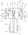
- Figure I eine schematische Darstellung mit Drehmomentabstützung über Hebel an der Achsbrücke,
- Figure II eine schematische Darstellung mit Drehmomentabstützung über Kegelzahnradsegmente.
- In beiden Zeichnungen sind gleiche Teile mit gleichen Bezugszeichen versehen. Der Antrieb des Rades erfolgt über ein in das Schienenrad integriertes Planetengetriebe. Dabei hat das Schienenrad 11 eine Hohlnabe 12, mit welcher das Rad 11 unter Zwischenschaltung von zwei Wälzlagern 13 auf dem Achsschenkel 14 angeordnet ist, welcher seinerseits mit den Wälzlagern 15 um eine etwa senkrecht stehende Achse 16 schwenkbar über die Achsbrücke 26 am Fahrwerkrahmen 17 befestigt ist. In der Hohlnabe 12 ist ausserdem mit Wälzlagern 18 das Hohlrad 19 eines Planetengetriebes angeordnet, welches mit den Planetenrädern 20 kämmt. Die Planetenräder 20 sind mit Wälzlagern 21 auf dem Träger 22 gelagert und kämmen mit dem Zentralrad 23, welches über Kupplungselemente und eine Kardangelenkwelle 24 mit der Antriebswelle 25 verbunden ist, die ihrerseits in an sich bekannter Weise in der Achsbrücke 26 angeordnet ist. Zwischen dem Hohlrad 19 des Planetengetriebes und der Achsbrücke 26 ist nach Fig.I eine an sich bekannte, in zwei Richtungen wirksame Drehmomentabstützung 27,28 in Form eines Gabelstückes 27, das auf einen Kugelkopf 28 wirkt, angeordnet. Das Stützmoment des Hohlrades 19 wird auf diese Weise auf die Achsbrücke 26 übertragen. Diese Drehmomentabstützung kann aber auch aus zwei Nocken bestehen, welche an der Achsbrücke 26 angeordnet sind, zwischen die sich ein am Hohlrad 19 befestigter Nocken erstreckt.
- Eine weitere Möglichkeit ist in Fig. II dargestellt, wo ein Kegelzahnrad 29 bzw. ein Segment davon mit der Achsbrücke 26 und ein anderes Kegelzahnrad 30 bzw. ein Segment davon mit dem abzustützenden Hohlrad 19 verbunden ist.
- Eine mögliche Ausführungsform zeichnet sich dadurch aus, dass die Schwenkachse 16 des Achsschenkels 14 in einer senkrecht zur Radebene stehenden Ebene liegt, die zwischen der Lagergruppe 18 des feststehenden Hohlrades 19 des Planetengetriebes und der Lagergruppe 13 des Rades 11 auf dem Achsschenkel 14 erstreckt.
- Der Planetenradträger 22 ist mit dem Rad 11 verbunden, wohingegen das Hohlrad 19 des Planetengetriebes über die Dreh momentabstützung 27,28 mit der Achsbrücke 26 verbunden ist und deshalb zu den nicht drehenden Teilen des Planetengetriebes gehört. Über die Antriebswelle 25 wird ein Drehmoment auf das Zentralrad 23 übertragen, welches ein Antriebs- oder ein Bremsmoment sein kann. Das am Hohlrad auftretende, zum Antriebs- oder Bremsmoment proportionale Stützmoment erzeugt in den Wirkflächen der Drehmomentabstützung 27,28 bzw. 29,30 eine Umfangskraft, die mit ihrem Hebelarm zur Schwenkachse 16 ein Kompensationsmoment erzeugt, welches dem aus Radumfangskraft und Lenkrollhalbmesser gebildeten Lenkmoment entgegenwirkt.
- Wenn in den Beispielen auch nur das Hohlrad 19 des Planetengetriebes als abzustützendes Reaktionsteil beschrieben ist, so kann doch ohne weiteres auch der Planetenradträger oder das innere Zentralrad des Planetengetriebes als abzustützendes Teil des Getriebes eingesetzt werden.
Claims (5)
Priority Applications (1)
| Application Number | Priority Date | Filing Date | Title |
|---|---|---|---|
| AT88114564T ATE90046T1 (de) | 1987-09-15 | 1988-09-07 | Vorrichtung zur lenkmoment-kompensation. |
Applications Claiming Priority (2)
| Application Number | Priority Date | Filing Date | Title |
|---|---|---|---|
| DE19873730936 DE3730936A1 (de) | 1987-09-15 | 1987-09-15 | Vorrichtung zur lenkmoment-kompensation |
| DE3730936 | 1987-09-15 |
Publications (3)
| Publication Number | Publication Date |
|---|---|
| EP0307770A2 true EP0307770A2 (de) | 1989-03-22 |
| EP0307770A3 EP0307770A3 (en) | 1989-10-18 |
| EP0307770B1 EP0307770B1 (de) | 1993-06-02 |
Family
ID=6336038
Family Applications (1)
| Application Number | Title | Priority Date | Filing Date |
|---|---|---|---|
| EP88114564A Expired - Lifetime EP0307770B1 (de) | 1987-09-15 | 1988-09-07 | Vorrichtung zur Lenkmoment-Kompensation |
Country Status (3)
| Country | Link |
|---|---|
| EP (1) | EP0307770B1 (de) |
| AT (1) | ATE90046T1 (de) |
| DE (2) | DE3730936A1 (de) |
Families Citing this family (1)
| Publication number | Priority date | Publication date | Assignee | Title |
|---|---|---|---|---|
| DE50310548D1 (de) | 2002-07-31 | 2008-11-06 | Daimler Ag | Verfahren zur bestimmung eines lenkradmoments |
Family Cites Families (2)
| Publication number | Priority date | Publication date | Assignee | Title |
|---|---|---|---|---|
| FR574272A (fr) * | 1923-01-24 | 1924-07-09 | Essieu pour matériel roulant tel que voitures de chemins de fer ou tramways | |
| DE3541732A1 (de) * | 1985-11-26 | 1987-05-27 | Duewag Ag | Lenkmoment-kompensation |
-
1987
- 1987-09-15 DE DE19873730936 patent/DE3730936A1/de active Granted
-
1988
- 1988-09-07 AT AT88114564T patent/ATE90046T1/de not_active IP Right Cessation
- 1988-09-07 DE DE8888114564T patent/DE3881461D1/de not_active Expired - Fee Related
- 1988-09-07 EP EP88114564A patent/EP0307770B1/de not_active Expired - Lifetime
Also Published As
| Publication number | Publication date |
|---|---|
| EP0307770B1 (de) | 1993-06-02 |
| DE3730936A1 (de) | 1989-03-23 |
| ATE90046T1 (de) | 1993-06-15 |
| EP0307770A3 (en) | 1989-10-18 |
| DE3881461D1 (de) | 1993-07-08 |
| DE3730936C2 (de) | 1993-02-11 |
Similar Documents
| Publication | Publication Date | Title |
|---|---|---|
| DE3442584C2 (de) | ||
| DE4140126C2 (de) | Laufwerk für Schienenfahrzeuge | |
| EP2512843B1 (de) | Vorrichtung zum verstellen von sturz und/oder spur der räder von radaufhängungen | |
| EP0235644A1 (de) | Triebdrehgestell für ein Schienenfahrzeug | |
| EP0507137B1 (de) | Lenkbarer Radantrieb | |
| EP0228617B1 (de) | Antriebsvorrichtung für wahlweise antreibbare Räder einer Tragachse eines Kraftfahrzeuges | |
| DE3827412C2 (de) | ||
| DE2636113C2 (de) | Vordere Radaufhängung für Kraftfahrzeuge mit Vorderradantrieb | |
| DE2556177B2 (de) | Lagerungsanordnung einer über ein Gleichlaufdrehgelenk antreibbaren Radnabe | |
| DE102021213069B3 (de) | Antrieb für eine Lenkachse eines Flurförderzeugs, Lenkachse und Flurförderzeug | |
| EP0050727B1 (de) | Drehgestell für Schienenfahrzeuge | |
| WO2020025083A1 (de) | Relativführungsvorrichtung für eine radträgerseitig angeordnete lenkanordnung | |
| DE3820967A1 (de) | Allradlenkeinrichtung fuer kraftfahrzeuge | |
| DE3730936C2 (de) | ||
| DE19646975B4 (de) | Aufhängungssystem für gelenkte Räder bei einem Fahrzeug | |
| DE2837302C2 (de) | ||
| DE3541732C2 (de) | ||
| DE8712475U1 (de) | Vorrichtung zur Lenkmoment-Kompensation | |
| DE19935160A1 (de) | Vorrichtung zur Erhöhung der Lenkfähigkeit getriebener Achsen | |
| EP0308760B1 (de) | Vorrichtung zur Lenkmoment-Kompensation bei Rädern mit Bremsen | |
| CH631664A5 (en) | Rail vehicle with bogies having at least two wheel sets | |
| EP0429095B1 (de) | Drehgestell mit gelenkten Radsätzen | |
| DE102015113156B4 (de) | Aktiver Radträger für ein Fahrzeug und Fahrwerk für ein Kraftfahrzeug sowie Fahrzeug | |
| EP1199237A1 (de) | Getriebe für Schienenfahrzeuge | |
| DE10041583A1 (de) | Befestigung für Differentialgetriebe |
Legal Events
| Date | Code | Title | Description |
|---|---|---|---|
| PUAI | Public reference made under article 153(3) epc to a published international application that has entered the european phase |
Free format text: ORIGINAL CODE: 0009012 |
|
| AK | Designated contracting states |
Kind code of ref document: A2 Designated state(s): AT CH DE ES FR GB IT LI NL SE |
|
| PUAL | Search report despatched |
Free format text: ORIGINAL CODE: 0009013 |
|
| AK | Designated contracting states |
Kind code of ref document: A3 Designated state(s): AT CH DE ES FR GB IT LI NL SE |
|
| 17P | Request for examination filed |
Effective date: 19900405 |
|
| 17Q | First examination report despatched |
Effective date: 19901217 |
|
| GRAA | (expected) grant |
Free format text: ORIGINAL CODE: 0009210 |
|
| AK | Designated contracting states |
Kind code of ref document: B1 Designated state(s): AT CH DE ES FR GB IT LI NL SE |
|
| PG25 | Lapsed in a contracting state [announced via postgrant information from national office to epo] |
Ref country code: IT Free format text: LAPSE BECAUSE OF FAILURE TO SUBMIT A TRANSLATION OF THE DESCRIPTION OR TO PAY THE FEE WITHIN THE PRESCRIBED TIME-LIMIT;WARNING: LAPSES OF ITALIAN PATENTS WITH EFFECTIVE DATE BEFORE 2007 MAY HAVE OCCURRED AT ANY TIME BEFORE 2007. THE CORRECT EFFECTIVE DATE MAY BE DIFFERENT FROM THE ONE RECORDED. Effective date: 19930602 Ref country code: FR Effective date: 19930602 Ref country code: SE Effective date: 19930602 Ref country code: ES Free format text: THE PATENT HAS BEEN ANNULLED BY A DECISION OF A NATIONAL AUTHORITY Effective date: 19930602 |
|
| REF | Corresponds to: |
Ref document number: 90046 Country of ref document: AT Date of ref document: 19930615 Kind code of ref document: T |
|
| REF | Corresponds to: |
Ref document number: 3881461 Country of ref document: DE Date of ref document: 19930708 |
|
| PG25 | Lapsed in a contracting state [announced via postgrant information from national office to epo] |
Ref country code: GB Effective date: 19930907 |
|
| GBT | Gb: translation of ep patent filed (gb section 77(6)(a)/1977) |
Effective date: 19930907 |
|
| EN | Fr: translation not filed | ||
| PG25 | Lapsed in a contracting state [announced via postgrant information from national office to epo] |
Ref country code: NL Effective date: 19940401 |
|
| PLBE | No opposition filed within time limit |
Free format text: ORIGINAL CODE: 0009261 |
|
| STAA | Information on the status of an ep patent application or granted ep patent |
Free format text: STATUS: NO OPPOSITION FILED WITHIN TIME LIMIT |
|
| GBPC | Gb: european patent ceased through non-payment of renewal fee |
Effective date: 19930907 |
|
| NLV4 | Nl: lapsed or anulled due to non-payment of the annual fee | ||
| 26N | No opposition filed | ||
| PGFP | Annual fee paid to national office [announced via postgrant information from national office to epo] |
Ref country code: DE Payment date: 19970924 Year of fee payment: 10 |
|
| PGFP | Annual fee paid to national office [announced via postgrant information from national office to epo] |
Ref country code: CH Payment date: 19970925 Year of fee payment: 10 Ref country code: AT Payment date: 19970925 Year of fee payment: 10 |
|
| PG25 | Lapsed in a contracting state [announced via postgrant information from national office to epo] |
Ref country code: AT Free format text: LAPSE BECAUSE OF NON-PAYMENT OF DUE FEES Effective date: 19980907 |
|
| PG25 | Lapsed in a contracting state [announced via postgrant information from national office to epo] |
Ref country code: CH Free format text: LAPSE BECAUSE OF NON-PAYMENT OF DUE FEES Effective date: 19980930 Ref country code: LI Free format text: LAPSE BECAUSE OF NON-PAYMENT OF DUE FEES Effective date: 19980930 |
|
| REG | Reference to a national code |
Ref country code: CH Ref legal event code: PL |
|
| PG25 | Lapsed in a contracting state [announced via postgrant information from national office to epo] |
Ref country code: DE Free format text: LAPSE BECAUSE OF NON-PAYMENT OF DUE FEES Effective date: 19990701 |