EP0307770A2 - Dispositif de compensation d'un couple de guidage - Google Patents
Dispositif de compensation d'un couple de guidage Download PDFInfo
- Publication number
- EP0307770A2 EP0307770A2 EP88114564A EP88114564A EP0307770A2 EP 0307770 A2 EP0307770 A2 EP 0307770A2 EP 88114564 A EP88114564 A EP 88114564A EP 88114564 A EP88114564 A EP 88114564A EP 0307770 A2 EP0307770 A2 EP 0307770A2
- Authority
- EP
- European Patent Office
- Prior art keywords
- wheel
- gear
- planetary gear
- steering
- reaction part
- Prior art date
- Legal status (The legal status is an assumption and is not a legal conclusion. Google has not performed a legal analysis and makes no representation as to the accuracy of the status listed.)
- Granted
Links
Images

Classifications
-
- B—PERFORMING OPERATIONS; TRANSPORTING
- B61—RAILWAYS
- B61F—RAIL VEHICLE SUSPENSIONS, e.g. UNDERFRAMES, BOGIES OR ARRANGEMENTS OF WHEEL AXLES; RAIL VEHICLES FOR USE ON TRACKS OF DIFFERENT WIDTH; PREVENTING DERAILING OF RAIL VEHICLES; WHEEL GUARDS, OBSTRUCTION REMOVERS OR THE LIKE FOR RAIL VEHICLES
- B61F5/00—Constructional details of bogies; Connections between bogies and vehicle underframes; Arrangements or devices for adjusting or allowing self-adjustment of wheel axles or bogies when rounding curves
- B61F5/38—Arrangements or devices for adjusting or allowing self- adjustment of wheel axles or bogies when rounding curves, e.g. sliding axles, swinging axles
-
- B—PERFORMING OPERATIONS; TRANSPORTING
- B61—RAILWAYS
- B61C—LOCOMOTIVES; MOTOR RAILCARS
- B61C15/00—Maintaining or augmenting the starting or braking power by auxiliary devices and measures; Preventing wheel slippage; Controlling distribution of tractive effort between driving wheels
- B61C15/14—Maintaining or augmenting the starting or braking power by auxiliary devices and measures; Preventing wheel slippage; Controlling distribution of tractive effort between driving wheels controlling distribution of tractive effort between driving wheels
Definitions
- the invention relates to a device for compensating undesirable steering torques on wheels of rail vehicles in particular, wherein a turning circumferential force which is proportional to the circumference of a driven or braked wheel and is determined by the circumferential wheel force and the steering roller radius is applied to the wheel in question from the outside.
- the present invention is therefore based on the object of avoiding the disadvantages of the known devices.
- the device should also be able to be used on small wheels.
- the solution to the problem is that the wheel is mounted with one or more roller bearings on the steering knuckle and the reaction part of the planetary gear to be supported with roller bearings in the hollow hub of the wheel and between the reaction part of the gearbox and the axle bridge a known per se effective in both directions of rotation and articulated torque support is arranged.
- the ring gear of the planetary gear is advantageously used as the reaction part to be supported, the ring gear being connected to the axle bridge via a lever serving as torque support or via two bevel gears which roll on one another or their segments.
- the advantage of the invention lies above all in the fact that the device can be used with all wheel sizes, which was previously not possible. In addition, there is no need for complex leverage to switch the moments against each other.
- the wheel is driven by a planetary gear integrated in the rail wheel.
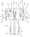
- the rail wheel 11 has a hollow hub 12 with which the wheel 11 with the interposition of two roller bearings 13 is arranged on the steering knuckle 14, which in turn is fastened with the roller bearings 15 about the axis bridge 26 on the chassis frame 17 so as to be pivotable about an approximately vertical axis 16.
- the ring gear 19 of a planetary gear is also arranged with roller bearings 18, which meshes with the planet gears 20.
- the planet gears 20 are supported with roller bearings 21 on the carrier 22 and mesh with the central wheel 23, which is connected via coupling elements and a universal joint shaft 24 to the drive shaft 25, which in turn is arranged in the axle bridge 26 in a manner known per se.
- a torque support 27, 28, known per se and effective in two directions, in the form of a fork piece 27, which acts on a ball head 28, is arranged according to FIG.
- the supporting torque of the ring gear 19 is transmitted to the axle bridge 26 in this way.
- This torque support can also consist of two cams, which are arranged on the axle bridge 26, between which a cam attached to the ring gear 19 extends.
- FIG. II Another possibility is shown in FIG. II, where a bevel gear 29 or a segment thereof is connected to the axle bridge 26 and another bevel gear 30 or a segment thereof is connected to the ring gear 19 to be supported.
- a possible embodiment is characterized in that the pivot axis 16 of the steering knuckle 14 lies in a plane perpendicular to the wheel plane, which extends between the bearing group 18 of the fixed ring gear 19 of the planetary gear and the bearing group 13 of the wheel 11 on the steering knuckle 14.
- the planet carrier 22 is connected to the wheel 11, whereas the ring gear 19 of the planetary gear via the rotation Torque support 27,28 is connected to the axle bridge 26 and therefore belongs to the non-rotating parts of the planetary gear.
- a torque is transmitted to the central wheel 23 via the drive shaft 25, which torque can be a drive or a braking torque.
- the support torque that occurs on the ring gear and is proportional to the drive or braking torque generates a circumferential force in the active surfaces of the torque support 27, 28 and 29.30, which generates a compensation torque with its lever arm to the pivot axis 16, which counteracts the steering torque formed from the wheel circumference force and the steering roller radius.
- the planet gear carrier or the inner central wheel of the planetary gear can also be used as a part of the transmission to be supported.
Landscapes
- Engineering & Computer Science (AREA)
- Mechanical Engineering (AREA)
- Transportation (AREA)
- Arrangement And Driving Of Transmission Devices (AREA)
- Retarders (AREA)
- Power Steering Mechanism (AREA)
- Steering-Linkage Mechanisms And Four-Wheel Steering (AREA)
Priority Applications (1)
| Application Number | Priority Date | Filing Date | Title |
|---|---|---|---|
| AT88114564T ATE90046T1 (de) | 1987-09-15 | 1988-09-07 | Vorrichtung zur lenkmoment-kompensation. |
Applications Claiming Priority (2)
| Application Number | Priority Date | Filing Date | Title |
|---|---|---|---|
| DE3730936 | 1987-09-15 | ||
| DE19873730936 DE3730936A1 (de) | 1987-09-15 | 1987-09-15 | Vorrichtung zur lenkmoment-kompensation |
Publications (3)
| Publication Number | Publication Date |
|---|---|
| EP0307770A2 true EP0307770A2 (fr) | 1989-03-22 |
| EP0307770A3 EP0307770A3 (en) | 1989-10-18 |
| EP0307770B1 EP0307770B1 (fr) | 1993-06-02 |
Family
ID=6336038
Family Applications (1)
| Application Number | Title | Priority Date | Filing Date |
|---|---|---|---|
| EP88114564A Expired - Lifetime EP0307770B1 (fr) | 1987-09-15 | 1988-09-07 | Dispositif de compensation d'un couple de guidage |
Country Status (3)
| Country | Link |
|---|---|
| EP (1) | EP0307770B1 (fr) |
| AT (1) | ATE90046T1 (fr) |
| DE (2) | DE3730936A1 (fr) |
Families Citing this family (1)
| Publication number | Priority date | Publication date | Assignee | Title |
|---|---|---|---|---|
| US7433768B2 (en) | 2002-07-31 | 2008-10-07 | Daimler Ag | Method for determining a steering-wheel torque |
Family Cites Families (2)
| Publication number | Priority date | Publication date | Assignee | Title |
|---|---|---|---|---|
| FR574272A (fr) * | 1923-01-24 | 1924-07-09 | Essieu pour matériel roulant tel que voitures de chemins de fer ou tramways | |
| DE3541732A1 (de) * | 1985-11-26 | 1987-05-27 | Duewag Ag | Lenkmoment-kompensation |
-
1987
- 1987-09-15 DE DE19873730936 patent/DE3730936A1/de active Granted
-
1988
- 1988-09-07 EP EP88114564A patent/EP0307770B1/fr not_active Expired - Lifetime
- 1988-09-07 DE DE8888114564T patent/DE3881461D1/de not_active Expired - Fee Related
- 1988-09-07 AT AT88114564T patent/ATE90046T1/de not_active IP Right Cessation
Also Published As
| Publication number | Publication date |
|---|---|
| EP0307770A3 (en) | 1989-10-18 |
| DE3730936C2 (fr) | 1993-02-11 |
| DE3881461D1 (de) | 1993-07-08 |
| EP0307770B1 (fr) | 1993-06-02 |
| ATE90046T1 (de) | 1993-06-15 |
| DE3730936A1 (de) | 1989-03-23 |
Similar Documents
| Publication | Publication Date | Title |
|---|---|---|
| DE3442584C2 (fr) | ||
| DE4140126C2 (de) | Laufwerk für Schienenfahrzeuge | |
| EP2512843B1 (fr) | Dispositif pour régler le carrossage et/ou la voie des roues de suspensions de roue | |
| EP0235644A1 (fr) | Bogie motorisé pour véhicule ferroviaire | |
| EP0507137B1 (fr) | Train d'entraînement dirigeable | |
| DE3827412C2 (fr) | ||
| EP0228617B1 (fr) | Dispositif d'entraînement pour des zones, entraînées au choix, d'un arbre de support d'un véhicule à moteur | |
| DE2636113C2 (de) | Vordere Radaufhängung für Kraftfahrzeuge mit Vorderradantrieb | |
| DE2556177B2 (de) | Lagerungsanordnung einer über ein Gleichlaufdrehgelenk antreibbaren Radnabe | |
| DE102021213069B3 (de) | Antrieb für eine Lenkachse eines Flurförderzeugs, Lenkachse und Flurförderzeug | |
| EP0050727B1 (fr) | Bogie pour véhicules ferroviaires | |
| DE3820967A1 (de) | Allradlenkeinrichtung fuer kraftfahrzeuge | |
| EP0307770A2 (fr) | Dispositif de compensation d'un couple de guidage | |
| DE19646975B4 (de) | Aufhängungssystem für gelenkte Räder bei einem Fahrzeug | |
| WO2020025083A1 (fr) | Dispositif de guidage relatif pour un ensemble de direction disposé côté support de roue | |
| DE2837302C2 (fr) | ||
| DE8712475U1 (de) | Vorrichtung zur Lenkmoment-Kompensation | |
| EP1200282A1 (fr) | Dispositif pour augmenter la dirigeabilite d'essieux menes | |
| DE3541732A1 (de) | Lenkmoment-kompensation | |
| EP0308760B1 (fr) | Dispositif de compensation du couple de guidage de roues munies de freins | |
| CH631664A5 (en) | Rail vehicle with bogies having at least two wheel sets | |
| EP0429095B1 (fr) | Bogie avec paires de roues guidées | |
| DE102015113156B4 (de) | Aktiver Radträger für ein Fahrzeug und Fahrwerk für ein Kraftfahrzeug sowie Fahrzeug | |
| EP1199237A1 (fr) | Transmission pour véhicule ferroviaire | |
| DE10041583A1 (de) | Befestigung für Differentialgetriebe |
Legal Events
| Date | Code | Title | Description |
|---|---|---|---|
| PUAI | Public reference made under article 153(3) epc to a published international application that has entered the european phase |
Free format text: ORIGINAL CODE: 0009012 |
|
| AK | Designated contracting states |
Kind code of ref document: A2 Designated state(s): AT CH DE ES FR GB IT LI NL SE |
|
| PUAL | Search report despatched |
Free format text: ORIGINAL CODE: 0009013 |
|
| AK | Designated contracting states |
Kind code of ref document: A3 Designated state(s): AT CH DE ES FR GB IT LI NL SE |
|
| 17P | Request for examination filed |
Effective date: 19900405 |
|
| 17Q | First examination report despatched |
Effective date: 19901217 |
|
| GRAA | (expected) grant |
Free format text: ORIGINAL CODE: 0009210 |
|
| AK | Designated contracting states |
Kind code of ref document: B1 Designated state(s): AT CH DE ES FR GB IT LI NL SE |
|
| PG25 | Lapsed in a contracting state [announced via postgrant information from national office to epo] |
Ref country code: IT Free format text: LAPSE BECAUSE OF FAILURE TO SUBMIT A TRANSLATION OF THE DESCRIPTION OR TO PAY THE FEE WITHIN THE PRESCRIBED TIME-LIMIT;WARNING: LAPSES OF ITALIAN PATENTS WITH EFFECTIVE DATE BEFORE 2007 MAY HAVE OCCURRED AT ANY TIME BEFORE 2007. THE CORRECT EFFECTIVE DATE MAY BE DIFFERENT FROM THE ONE RECORDED. Effective date: 19930602 Ref country code: FR Effective date: 19930602 Ref country code: SE Effective date: 19930602 Ref country code: ES Free format text: THE PATENT HAS BEEN ANNULLED BY A DECISION OF A NATIONAL AUTHORITY Effective date: 19930602 |
|
| REF | Corresponds to: |
Ref document number: 90046 Country of ref document: AT Date of ref document: 19930615 Kind code of ref document: T |
|
| REF | Corresponds to: |
Ref document number: 3881461 Country of ref document: DE Date of ref document: 19930708 |
|
| PG25 | Lapsed in a contracting state [announced via postgrant information from national office to epo] |
Ref country code: GB Effective date: 19930907 |
|
| GBT | Gb: translation of ep patent filed (gb section 77(6)(a)/1977) |
Effective date: 19930907 |
|
| EN | Fr: translation not filed | ||
| PG25 | Lapsed in a contracting state [announced via postgrant information from national office to epo] |
Ref country code: NL Effective date: 19940401 |
|
| PLBE | No opposition filed within time limit |
Free format text: ORIGINAL CODE: 0009261 |
|
| STAA | Information on the status of an ep patent application or granted ep patent |
Free format text: STATUS: NO OPPOSITION FILED WITHIN TIME LIMIT |
|
| GBPC | Gb: european patent ceased through non-payment of renewal fee |
Effective date: 19930907 |
|
| NLV4 | Nl: lapsed or anulled due to non-payment of the annual fee | ||
| 26N | No opposition filed | ||
| PGFP | Annual fee paid to national office [announced via postgrant information from national office to epo] |
Ref country code: DE Payment date: 19970924 Year of fee payment: 10 |
|
| PGFP | Annual fee paid to national office [announced via postgrant information from national office to epo] |
Ref country code: CH Payment date: 19970925 Year of fee payment: 10 Ref country code: AT Payment date: 19970925 Year of fee payment: 10 |
|
| PG25 | Lapsed in a contracting state [announced via postgrant information from national office to epo] |
Ref country code: AT Free format text: LAPSE BECAUSE OF NON-PAYMENT OF DUE FEES Effective date: 19980907 |
|
| PG25 | Lapsed in a contracting state [announced via postgrant information from national office to epo] |
Ref country code: CH Free format text: LAPSE BECAUSE OF NON-PAYMENT OF DUE FEES Effective date: 19980930 Ref country code: LI Free format text: LAPSE BECAUSE OF NON-PAYMENT OF DUE FEES Effective date: 19980930 |
|
| REG | Reference to a national code |
Ref country code: CH Ref legal event code: PL |
|
| PG25 | Lapsed in a contracting state [announced via postgrant information from national office to epo] |
Ref country code: DE Free format text: LAPSE BECAUSE OF NON-PAYMENT OF DUE FEES Effective date: 19990701 |