EP0307800B1 - Imprimante par matrice de points - Google Patents
Imprimante par matrice de points Download PDFInfo
- Publication number
- EP0307800B1 EP0307800B1 EP88114695A EP88114695A EP0307800B1 EP 0307800 B1 EP0307800 B1 EP 0307800B1 EP 88114695 A EP88114695 A EP 88114695A EP 88114695 A EP88114695 A EP 88114695A EP 0307800 B1 EP0307800 B1 EP 0307800B1
- Authority
- EP
- European Patent Office
- Prior art keywords
- write
- rows
- distance
- writing
- heads
- Prior art date
- Legal status (The legal status is an assumption and is not a legal conclusion. Google has not performed a legal analysis and makes no representation as to the accuracy of the status listed.)
- Expired - Lifetime
Links
- 239000011159 matrix material Substances 0.000 title claims description 21
- 239000003086 colorant Substances 0.000 claims description 12
- 230000010363 phase shift Effects 0.000 claims description 10
- 238000004519 manufacturing process Methods 0.000 description 3
- 238000005516 engineering process Methods 0.000 description 1
- 125000006850 spacer group Chemical group 0.000 description 1
- 230000007704 transition Effects 0.000 description 1
Images


Classifications
-
- B—PERFORMING OPERATIONS; TRANSPORTING
- B41—PRINTING; LINING MACHINES; TYPEWRITERS; STAMPS
- B41J—TYPEWRITERS; SELECTIVE PRINTING MECHANISMS, i.e. MECHANISMS PRINTING OTHERWISE THAN FROM A FORME; CORRECTION OF TYPOGRAPHICAL ERRORS
- B41J2/00—Typewriters or selective printing mechanisms characterised by the printing or marking process for which they are designed
- B41J2/485—Typewriters or selective printing mechanisms characterised by the printing or marking process for which they are designed characterised by the process of building-up characters or image elements applicable to two or more kinds of printing or marking processes
- B41J2/505—Typewriters or selective printing mechanisms characterised by the printing or marking process for which they are designed characterised by the process of building-up characters or image elements applicable to two or more kinds of printing or marking processes from an assembly of identical printing elements
- B41J2/515—Typewriters or selective printing mechanisms characterised by the printing or marking process for which they are designed characterised by the process of building-up characters or image elements applicable to two or more kinds of printing or marking processes from an assembly of identical printing elements line printer type
-
- B—PERFORMING OPERATIONS; TRANSPORTING
- B41—PRINTING; LINING MACHINES; TYPEWRITERS; STAMPS
- B41J—TYPEWRITERS; SELECTIVE PRINTING MECHANISMS, i.e. MECHANISMS PRINTING OTHERWISE THAN FROM A FORME; CORRECTION OF TYPOGRAPHICAL ERRORS
- B41J2202/00—Embodiments of or processes related to ink-jet or thermal heads
- B41J2202/01—Embodiments of or processes related to ink-jet heads
- B41J2202/20—Modules
Definitions
- Matrix writing devices are generally understood to mean all writing devices which apply gradual, alphanumeric characters or images to a recording medium. Examples of this are dot matrix printers or ink drop printers. The width of the print heads is limited for manufacturing reasons. For the same reasons, the distance between adjacent writing elements cannot be reduced arbitrarily.
- An ink mosaic writing device of this type is known for example from DE 25 27 647 CI. The maximum possible resolution is approx. 4 writing elements, i.e. Ink nozzles per mm.
- US 4,593,295 shows a matrix writing device for multi-color printing, in which a block with a plurality of rows of writing nozzles arranged for gaps is used for different colors. This block is moved across the paper transport direction in both directions. In order to be able to print in both directions without noticeable differences in the color texture, the colors are distributed over the staggered rows in such a way that the different color texture results for neighboring points and thus outside the color discrimination of the human eye.
- the present invention has for its object to provide a matrix writing device of the type mentioned that such that the resolution is better than that of the individual with a writing width that is greater than that of a single printhead and with a minimum number of necessary rows of printheads Print head and / or multi-color printing is made possible.
- Phase means the distance between the individual writing elements.
- the distance between two writing elements in a writing head corresponds to a phase shift of 360 °.
- the arrangement of the write heads according to the invention makes it possible to obtain an increased resolution and at the same time a large write width with a minimal number of rows of write heads. If one were to attempt to achieve this goal with the known means, one would first have to arrange two rows of these write heads offset from one another to cover the entire desired writing width in order to achieve the basic resolution, which means the resolution of the individual write heads. If you only wanted to double the resolution, two further rows would have to be arranged with a gap between them, this time with a phase shift of 180 to that of the first two rows. In total, four rows of print heads would be necessary. Six rows would be necessary for a triple resolution.
- the matrix writing device can also be used to achieve multi-color printing. If the normal raster principle is used, in which there is a shift between the individual color points, the factor by which the resolution should otherwise be increased can only be replaced by the number of desired colors. Four rows are required for three-color printing, each row being assigned a color and the first and fourth rows using the same color.
- a multi-color print "in phase” is desired, ie a print in which ver If different colors are assigned to the same recording point, then according to the invention the phase shift is selected to be zero and the color of the print heads is cyclically interchanged in each row and between the rows.
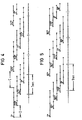
- a write head (1) is shown schematically in FIG. 1, which can represent, for example, the top view of the nozzle outlet openings of a piezoelectric ink drop recorder.
- the writing elements (2) are practically formed by the nozzle outlet openings.
- a needle or thermal printer can also be used instead of an ink drop pen. It is only essential that e.g. the alphanumeric characters or images to be displayed on a record carrier consist of the points of a matrix.
- A denotes the write width of the write head (1), i.e. the distance from the center of the extreme left to the center of the extreme right writing element.
- B denotes the width of the entire print head and s the distance between two writing elements (calculated from center to center).
- FIG. 2 A known writing device is shown schematically in FIG. 2, in which it is only a matter of increasing the writing width in the case of stationary writing heads with unchanged resolution.
- the resolution of the individual write head is referred to below as the basic resolution G.
- four write heads (3 to 6) are arranged zigzag in a row in two rows.
- the write heads (1, 3 to 6,) have edge regions that are larger than half the distance between two writing elements. It is therefore not possible to arrange the print heads in a row without having to accept resolution losses in the transition area from one write head to another. With the extremely small dimensions - about four writing elements per mm can be achieved in practice today - it is hardly possible in terms of manufacturing technology to achieve narrower edge areas.
- FIG. 3 shows an arrangement known, for example from DE 33 06 098 A1, for increasing the resolution with a writing width which approximately corresponds to the writing width A.
- Three write heads (7-9) are shown, each of which is 120 "out of phase with each other. This enables a resolution to be achieved that is three times higher than the basic resolution G.
- the factor by which the basic resolution must be multiplied in order to achieve the one achieved Achieving resolution is denoted by n. By this factor, the distances between the matrix points that can be generated by the writing elements are practically reduced compared to the distance between the writing elements themselves.
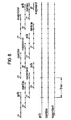
- the matrix writing device can also be used for multi-color representations.
- 6 shows an exemplary embodiment for a three-color representation with a resolution that corresponds to the basic resolution G.
- the basic resolution is four writing elements per mm.
- the three colors should be shown shifted against each other according to the raster principle.
- the colors selected are, for example, yellow, cyan and magenta.
- the phase shift is again 120 0. In the lower part of FIG. 6, the recording points of the three colors are shown with the corresponding phase shift.
- FIG. 7 shows a further example for four colors, black being added as the fourth color.
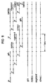
- multi-color representations are intended in which all colors are to a certain extent "in phase", i.e. that they are plotted on top of one another on the same recording point, the formulas have to be varied slightly.
- M m x n.
- the shift results in D m x s.
- the width of the print head here B (n + I) x m + s.
- the number of rows of write heads required is n + I.
- FIGS. 8 and 9 show two examples of three and four-color representations.
- n 8
- a four-color display with double basic resolution can be obtained for each color.
- 9 rows of write heads are required compared to 16 rows in a conventional arrangement. This case is shown in FIG 10.
- FIG. 11 shows schematically the outer basic structure of a complete matrix writing device.
- a recording medium (12) for example normal registration paper, is drawn over transport rollers (10, 11) in the direction of arrow (13) via a spacer (14) on the end face (15) of a housing (16).
- the connecting line (17) is guided into the housing (16) and is provided at its free end with a plug (18) for connection to a corresponding control device that supplies the control signals for recording the desired courses, characters or images.
- the housing (16) contains the rows of write heads arranged according to the invention.
Landscapes
- Ink Jet (AREA)
- Dot-Matrix Printers And Others (AREA)
- Printers Characterized By Their Purpose (AREA)
- Printers Or Recording Devices Using Electromagnetic And Radiation Means (AREA)
Claims (6)
Applications Claiming Priority (2)
| Application Number | Priority Date | Filing Date | Title |
|---|---|---|---|
| DE19873730844 DE3730844A1 (de) | 1987-09-14 | 1987-09-14 | Matrix-schreibeinrichtung |
| DE3730844 | 1987-09-14 |
Publications (2)
| Publication Number | Publication Date |
|---|---|
| EP0307800A1 EP0307800A1 (fr) | 1989-03-22 |
| EP0307800B1 true EP0307800B1 (fr) | 1992-03-11 |
Family
ID=6335975
Family Applications (1)
| Application Number | Title | Priority Date | Filing Date |
|---|---|---|---|
| EP88114695A Expired - Lifetime EP0307800B1 (fr) | 1987-09-14 | 1988-09-08 | Imprimante par matrice de points |
Country Status (4)
| Country | Link |
|---|---|
| US (1) | US4922271A (fr) |
| EP (1) | EP0307800B1 (fr) |
| JP (1) | JPH01127364A (fr) |
| DE (2) | DE3730844A1 (fr) |
Families Citing this family (23)
| Publication number | Priority date | Publication date | Assignee | Title |
|---|---|---|---|---|
| CA2049571C (fr) | 1990-10-19 | 2004-01-13 | Kent D. Vincent | Imprimante thermique a jet d'encre haute definition |
| US5347617A (en) * | 1990-11-09 | 1994-09-13 | Dataproducts Corporation | Printer having a multiple scan line printhead controller |
| US5546114A (en) * | 1991-09-18 | 1996-08-13 | Tektronix, Inc. | Systems and methods for making printed products |
| US5512930A (en) * | 1991-09-18 | 1996-04-30 | Tektronix, Inc. | Systems and methods of printing by applying an image enhancing precoat |
| US5483268A (en) * | 1992-04-17 | 1996-01-09 | Rohm Co., Ltd. | Method for driving ink jet print head |
| JPH05330085A (ja) * | 1992-05-29 | 1993-12-14 | Yoshida Kogyo Kk <Ykk> | インクジェットによる連続走行帯状物用プリンター |
| DE4336416A1 (de) * | 1993-10-19 | 1995-08-24 | Francotyp Postalia Gmbh | Face-Shooter-Tintenstrahldruckkopf und Verfahren zu seiner Herstellung |
| JPH0825635A (ja) * | 1994-07-21 | 1996-01-30 | Canon Inc | インクジェットプリント装置およびプリントヘッドユニット |
| US6062666A (en) * | 1994-11-07 | 2000-05-16 | Canon Kabushiki Kaisha | Ink jet recording method and apparatus beginning driving cycle with discharge elements other than at ends of substrates |
| US5598191A (en) * | 1995-06-01 | 1997-01-28 | Xerox Corporation | Architecture for an ink jet printer with offset arrays of ejectors |
| JP3382438B2 (ja) * | 1995-12-20 | 2003-03-04 | キヤノン株式会社 | 記録装置 |
| US6074112A (en) * | 1996-12-19 | 2000-06-13 | Agfa-Gevaert | Printer for large format printing |
| US6102523A (en) * | 1996-12-19 | 2000-08-15 | Agfa-Gevaert | Printer for large format printing using a direct electrostatic printing (DEP) engine |
| US5923348A (en) | 1997-02-26 | 1999-07-13 | Lexmark International, Inc. | Method of printing using a printhead having multiple rows of ink emitting orifices |
| US6257699B1 (en) | 1999-10-13 | 2001-07-10 | Xerox Corporation | Modular carriage assembly for use with high-speed, high-performance, printing device |
| FR2807360B1 (fr) * | 2000-04-11 | 2002-10-31 | Nipson | Procede et dispositif de jonction de modules ou barrettes de tetes magnetographiques |
| AU2002223484A1 (en) | 2000-11-17 | 2002-05-27 | Koenig And Bauer Aktiengesellschaft | Printing devices comprising a plurality of print heads |
| DE10057061C1 (de) * | 2000-11-17 | 2002-05-23 | Koenig & Bauer Ag | Druckvorrichtung |
| US6663222B2 (en) | 2000-12-22 | 2003-12-16 | Agfa-Gevaert | Ink jet printer with nozzle arrays that are moveable with respect to each other |
| DE10256614A1 (de) * | 2002-12-03 | 2004-06-17 | Basf Ag | Vorrichtung und Verfahren zur Herstellung von Flexodruckplatten für den Zeitungsdruck mittels digitaler Bebilderung |
| US7530666B2 (en) * | 2004-03-26 | 2009-05-12 | Canon Kabushiki Kaisha | Liquid discharge head, liquid discharge recording apparatus and liquid discharge recording method |
| US7645020B2 (en) | 2004-07-27 | 2010-01-12 | Neopost Technologies | High speed serial printing using printheads |
| DE102005024007B4 (de) * | 2005-05-25 | 2008-05-29 | Koenig & Bauer Aktiengesellschaft | Druckwerk mit Farbwerk zum Auftragen von Druckfarbe auf einen Formzylinder einer Druckmaschine |
Family Cites Families (13)
| Publication number | Priority date | Publication date | Assignee | Title |
|---|---|---|---|---|
| US3560641A (en) * | 1968-10-18 | 1971-02-02 | Mead Corp | Image construction system using multiple arrays of drop generators |
| DE2527647C3 (de) * | 1975-06-20 | 1981-06-25 | Siemens AG, 1000 Berlin und 8000 München | Mit Flüssigkeitströpfchen arbeitendes Schreibgerät |
| US4063254A (en) * | 1976-06-28 | 1977-12-13 | International Business Machines Corporation | Multiple array printer |
| US4232324A (en) * | 1978-06-05 | 1980-11-04 | International Business Machines Corporation | Apparatus for arranging scanning heads for interlacing |
| US4284001A (en) * | 1979-10-19 | 1981-08-18 | International Business Machines Corp. | Head image generator for a matrix printer |
| DE3278761D1 (en) * | 1981-12-21 | 1988-08-18 | Ibm | Selective density printing using dot matrix print heads in fixed spatial relation |
| DE3208104A1 (de) * | 1982-03-06 | 1983-09-08 | Philips Patentverwaltung Gmbh, 2000 Hamburg | Druckkopf fuer einen matrixdrucker |
| US4593295A (en) * | 1982-06-08 | 1986-06-03 | Canon Kabushiki Kaisha | Ink jet image recording device with pitch-shifted recording elements |
| JPS5995159A (ja) * | 1982-11-22 | 1984-06-01 | Fujitsu Ltd | シリアルドツトプリンタ |
| DE3306098A1 (de) * | 1983-02-22 | 1984-08-23 | Siemens AG, 1000 Berlin und 8000 München | Piezoelektrisch betriebener schreibkopf mit kanalmatrize |
| NL8402353A (nl) * | 1984-07-26 | 1986-02-17 | Philips Nv | Werkwijze en drukinrichting voor het lijnsgewijs drukken op een drager van door punt- of lijnvormige elementen samengestelde beelden. |
| US4680596A (en) * | 1984-08-02 | 1987-07-14 | Metromedia Company | Method and apparatus for controlling ink-jet color printing heads |
| US4660052A (en) * | 1986-06-06 | 1987-04-21 | Mitsuhiro Kaiya | Heat-sensitive recording apparatus |
-
1987
- 1987-09-14 DE DE19873730844 patent/DE3730844A1/de not_active Withdrawn
-
1988
- 1988-09-08 DE DE8888114695T patent/DE3869026D1/de not_active Expired - Lifetime
- 1988-09-08 EP EP88114695A patent/EP0307800B1/fr not_active Expired - Lifetime
- 1988-09-12 JP JP63228293A patent/JPH01127364A/ja active Pending
- 1988-09-14 US US07/244,508 patent/US4922271A/en not_active Expired - Fee Related
Non-Patent Citations (1)
| Title |
|---|
| PATENT ABSTRACTS OF JAPAN, Band 8, Nr. 207 (M-327)[1644], 21. September 1984, Seite 53; JP-A-59 95 159 (FUJITSU K.K.) 01-06-1984 * |
Also Published As
| Publication number | Publication date |
|---|---|
| DE3730844A1 (de) | 1989-03-23 |
| JPH01127364A (ja) | 1989-05-19 |
| US4922271A (en) | 1990-05-01 |
| EP0307800A1 (fr) | 1989-03-22 |
| DE3869026D1 (de) | 1992-04-16 |
Similar Documents
| Publication | Publication Date | Title |
|---|---|---|
| EP0307800B1 (fr) | Imprimante par matrice de points | |
| DE3615604C2 (fr) | ||
| DE69017995T2 (de) | Verkettetes Druckverfahren. | |
| DE69807431T2 (de) | Tintenstrahldrucksystem mit Ausrichtung von Schreibstiften und Verfahren | |
| DE69426519T2 (de) | Gemischte Druckauflösung für ein- und mehrfarbige Drucker | |
| DE69228030T2 (de) | Tintenstrahlaufzeichnungsverfahren | |
| DE102005063486B3 (de) | Tintenstrahldruckvorrichtung | |
| DE69011319T2 (de) | Bidirektionales farbstrahldrucken mit heissschmelzender tinte. | |
| DE69415214T2 (de) | Verbesserter Tintenstrahl-Druckkopf für Punktmatrixdrucker | |
| EP0255867B1 (fr) | Imprimante à projection d'encre avec des têtes d'impression interchangeables | |
| DE2753967C2 (de) | Punktmatrixdrucker mit einer Steuerschaltung für einen Druckkopf | |
| DE3317079C2 (fr) | ||
| DE69525329T2 (de) | Verfahren zum Übergang zwischen Tintenstrahldruckbetriebsverfahren | |
| DE60314705T2 (de) | Verfahren für Mehrfarbentintenstrahldrucken und Druckgerät | |
| DE60129911T2 (de) | Mehrfarbiger Tintenstrahlkopf | |
| EP0027967B1 (fr) | Procédé de représentation d'images en demi-teinte | |
| DE69323679T2 (de) | Farbänderungskontrollmethode für Tintenstrahldrucker | |
| DE69809002T2 (de) | Druckverfahren mit Tintenstrahdrucker mit verbesserter horizontalen Auflösung | |
| DE2840279C2 (de) | Tintenstrahldrucker | |
| DE60001397T2 (de) | Tintenstrahldrucken in einem einmaligen durchgang | |
| DE3620334A1 (de) | Druckverfahren | |
| DE60038419T2 (de) | Verfahren zum Bedrucken eines Substrats und eine Druckvorrichtung geeignet zur Verwendung dieses Verfahrens | |
| DE69528959T2 (de) | Tintenstrahldruckverfahren unter Verwendung von Farbenverstärkung in schwarzen Gebieten | |
| DE3308353C2 (de) | Farbausstoßkopf für einen Farbstrahldrucker | |
| DE69515542T2 (de) | Verfahren zur Verbesserung des Druckens von graphischen Bildern und entsprechendes Tintenstrahldruckgerät |
Legal Events
| Date | Code | Title | Description |
|---|---|---|---|
| PUAI | Public reference made under article 153(3) epc to a published international application that has entered the european phase |
Free format text: ORIGINAL CODE: 0009012 |
|
| AK | Designated contracting states |
Kind code of ref document: A1 Designated state(s): DE FR GB IT NL SE |
|
| 17P | Request for examination filed |
Effective date: 19890706 |
|
| 17Q | First examination report despatched |
Effective date: 19901212 |
|
| GRAA | (expected) grant |
Free format text: ORIGINAL CODE: 0009210 |
|
| AK | Designated contracting states |
Kind code of ref document: B1 Designated state(s): DE FR GB IT NL SE |
|
| PG25 | Lapsed in a contracting state [announced via postgrant information from national office to epo] |
Ref country code: SE Effective date: 19920311 |
|
| REF | Corresponds to: |
Ref document number: 3869026 Country of ref document: DE Date of ref document: 19920416 |
|
| ET | Fr: translation filed | ||
| ITF | It: translation for a ep patent filed | ||
| GBT | Gb: translation of ep patent filed (gb section 77(6)(a)/1977) | ||
| PLBE | No opposition filed within time limit |
Free format text: ORIGINAL CODE: 0009261 |
|
| STAA | Information on the status of an ep patent application or granted ep patent |
Free format text: STATUS: NO OPPOSITION FILED WITHIN TIME LIMIT |
|
| 26N | No opposition filed | ||
| PGFP | Annual fee paid to national office [announced via postgrant information from national office to epo] |
Ref country code: GB Payment date: 19940815 Year of fee payment: 7 |
|
| PGFP | Annual fee paid to national office [announced via postgrant information from national office to epo] |
Ref country code: FR Payment date: 19940920 Year of fee payment: 7 |
|
| PGFP | Annual fee paid to national office [announced via postgrant information from national office to epo] |
Ref country code: NL Payment date: 19940930 Year of fee payment: 7 |
|
| PGFP | Annual fee paid to national office [announced via postgrant information from national office to epo] |
Ref country code: DE Payment date: 19941118 Year of fee payment: 7 |
|
| PG25 | Lapsed in a contracting state [announced via postgrant information from national office to epo] |
Ref country code: GB Effective date: 19950908 |
|
| PG25 | Lapsed in a contracting state [announced via postgrant information from national office to epo] |
Ref country code: NL Effective date: 19960401 |
|
| GBPC | Gb: european patent ceased through non-payment of renewal fee |
Effective date: 19950908 |
|
| PG25 | Lapsed in a contracting state [announced via postgrant information from national office to epo] |
Ref country code: FR Effective date: 19960531 |
|
| PG25 | Lapsed in a contracting state [announced via postgrant information from national office to epo] |
Ref country code: DE Effective date: 19960601 |
|
| NLV4 | Nl: lapsed or anulled due to non-payment of the annual fee |
Effective date: 19960401 |
|
| REG | Reference to a national code |
Ref country code: FR Ref legal event code: ST |
|
| PG25 | Lapsed in a contracting state [announced via postgrant information from national office to epo] |
Ref country code: IT Free format text: LAPSE BECAUSE OF NON-PAYMENT OF DUE FEES;WARNING: LAPSES OF ITALIAN PATENTS WITH EFFECTIVE DATE BEFORE 2007 MAY HAVE OCCURRED AT ANY TIME BEFORE 2007. THE CORRECT EFFECTIVE DATE MAY BE DIFFERENT FROM THE ONE RECORDED. Effective date: 20050908 |