EP0307876A2 - Ophthalmische Linsen - Google Patents
Ophthalmische Linsen Download PDFInfo
- Publication number
- EP0307876A2 EP0307876A2 EP88114978A EP88114978A EP0307876A2 EP 0307876 A2 EP0307876 A2 EP 0307876A2 EP 88114978 A EP88114978 A EP 88114978A EP 88114978 A EP88114978 A EP 88114978A EP 0307876 A2 EP0307876 A2 EP 0307876A2
- Authority
- EP
- European Patent Office
- Prior art keywords
- area
- lens
- areas
- accordance
- viewing
- Prior art date
- Legal status (The legal status is an assumption and is not a legal conclusion. Google has not performed a legal analysis and makes no representation as to the accuracy of the status listed.)
- Withdrawn
Links
- 238000002156 mixing Methods 0.000 claims abstract description 15
- 230000000750 progressive effect Effects 0.000 claims description 13
- 239000000203 mixture Substances 0.000 claims description 7
- 208000001491 myopia Diseases 0.000 claims description 3
- 230000004438 eyesight Effects 0.000 description 12
- 238000000034 method Methods 0.000 description 7
- 230000008901 benefit Effects 0.000 description 6
- 230000007704 transition Effects 0.000 description 4
- 239000002537 cosmetic Substances 0.000 description 3
- 239000011521 glass Substances 0.000 description 3
- 201000010041 presbyopia Diseases 0.000 description 3
- 230000004308 accommodation Effects 0.000 description 2
- 239000000919 ceramic Substances 0.000 description 2
- 230000007812 deficiency Effects 0.000 description 2
- 239000002184 metal Substances 0.000 description 2
- 238000012986 modification Methods 0.000 description 2
- 230000004048 modification Effects 0.000 description 2
- 201000009310 astigmatism Diseases 0.000 description 1
- 238000010276 construction Methods 0.000 description 1
- 238000003754 machining Methods 0.000 description 1
- 238000004519 manufacturing process Methods 0.000 description 1
- 239000005304 optical glass Substances 0.000 description 1
- 230000002093 peripheral effect Effects 0.000 description 1
- 230000005043 peripheral vision Effects 0.000 description 1
- 238000005498 polishing Methods 0.000 description 1
- 230000000007 visual effect Effects 0.000 description 1
Images


Classifications
-
- G—PHYSICS
- G02—OPTICS
- G02C—SPECTACLES; SUNGLASSES OR GOGGLES INSOFAR AS THEY HAVE THE SAME FEATURES AS SPECTACLES; CONTACT LENSES
- G02C7/00—Optical parts
- G02C7/02—Lenses; Lens systems ; Methods of designing lenses
- G02C7/06—Lenses; Lens systems ; Methods of designing lenses bifocal; multifocal ; progressive
Definitions
- the present invention relates to ophthalmic lenses for use in eye wear.
- Multifocal lenses have been used in situations requiring spectacle correction for presbyopia. Often patients using such correction devices encounter disturbing problems inherent in many designs. These problems include image jump, limited range of clear vision, annoying reflections from the edge of lens segments and cosmetic objections. For example, conventional flat top, curve top and ribbon shaped segments have ledges which either protrude from the plastic lenses or are fused within the glass lenses. These ledges often reflect light into the wearer's eye and are cosmetically unappealing because of their obviousness to the observer.
- Some progressives also include blended areas which extend all the way to the edges of the lens. These blended areas are intended to minimize distortion and achieve cosmetic appeal. The erroneous assumption made by the designers of such lenses is that patients can tolerate distance distortion. Still another deficiency of many progressive lenses is that they have narrow corridors of power increase which are difficult for opticians to correctly position, especially for reading. It is also difficult for the user to aim the lens toward the reading area.
- an object of the present invention to provide an ophthalmic lens which provides clear viewing substantially without distortion in both near and distance viewing areas.
- a multifocal ophthalmic lens which comprises a first substantially spherical area for distance viewing, a second substantially spherical area for near viewing having a desired width and height and being surrounded on a plurality of sides by the first area, and relatively narrow areas intermediate the first and second areas for blending the second area into the first area.
- the lens design of the present invention may also include a third substantially spherical area adjacent the second area for increasing the near viewing range in a substantially contiguous manner.
- the near distance viewing area(s) are preferably inclined nasalward.
- the many advantages attendant to this design include minimal areas of distortion resulting from the blending of various lens segments, the relative absence of distortion in the long distance viewing area, an extended near vision viewing range, and ease of fit for a dispensing optician.
- the present invention relates to a multifocal ophthalmic lens for providing correction for presbyopia.
- Lenses in accordance with the present invention provide the desired correction without encountering problems such as image jump, annoying reflections from segment edges and large amounts of distortion.
- lenses in accordance with the present invention are cosmetically appealing.
- Figure 1 illustrates a multifocal lens 10 in accordance with the present invention.
- the lens 10 is characterized by a first substantially spherical area 12 for distance viewing, a second substantially spherical area 14 for near viewing, an optional third substantially spherical area 16 for extending the viewing range provided by the second area in a substantially contiguous manner, and areas 18 for blending the second and third areas into the first area.
- the sphericity of the areas 12, 14 and/or 16 is important for a number of reasons.
- the relatively narrow blend areas 18 are located on the sides of the areas 14 and 16, at portions of the top of area 16 and at the bottom of the near distance viewing area 14. In most cases, these blend areas will have a width of less than about 10 mm, preferably less than about 6 mm. This is also quite significant in terms of providing a lens with relatively little distortion. It should also be noted that the lens of the present invention differs from many progressive lenses in that the blend areas do not extend to the lens edges. As will be described in more detail hereinafter, the blend areas 18 may be produced using any suitable technique known in the art. Preferably, the curvature of these areas is determined through the use of sinusoidal curves.
- the depth, width and shape of the areas 14 and 16 can be arbitrarily chosen for convenience and patient comfort.
- the width of each near distance viewing area may be in the range of from about 18 mm. to about 45 mm. and the depth of each area may be in the range of from about 11 mm. to about 28 mm.
- each of the areas 14 and 16 have a substantially flat top portion.
- the long distance viewing area 12 surrounds each of the areas 14 and 16 on a plurality of sides, preferably at least three sides.
- the intermediate viewing or third area 16 is truly optional in that it may not be needed at all for a patient.
- Bifocal ophthalmic lenses such as that shown in Figure 3 may be formed using the same design considerations, e.g. sphericity, sinusoidal blending, etc. as those described in connection with lenses having three viewing areas.
- Such a bifocal lens has a first substantially spherical area 12′ for distance viewing, a second substantially spherical area 14′ for near viewing having a desired width and height and surrounded on one or more sides by the first area and relatively narrow areas 18′ intermediate the first and second areas for blending the second area into the first area.
- the near viewing area 14′ of the bifocal lenses formed in accordance with the present invention may have any desired add power. It is prefered in the bifocal lens however that the near viewing area 14′ have a substantially flat top portion.
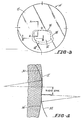
- the technique employed to sinusoidally blend the distance viewing area 12′ and the near viewing area 14′ is illustrated in Figures 4 and 5.
- the area 12′ is defined by a first arc having a radius R1 while the area 14′ is defined by a second arc having a radius R2 different from the radius R1.
- the two arcs substantially coincide for some distance. This coincidence negates the need to blend the very top portion of the area 14′ into the area 12′. Other portions where the two arcs do not coincide are blended by areas 18′. These areas adjacent the top portion of the area 14′ are blended by drawing two arcs 30 and 32, each having the same radius.
- the radius is that of the maximum curve that contacts a segment of a viewing area and the other arc.
- the arc 30 is drawn on one side of the lens while the arc 32 is drawn on the opposite side with one arc tangent to a portion of the arc defining viewing area 12′, the other arc tangent to a portion of the arc defining area 14′, and the two arcs 30 and 32 tangent to each other. Since the two arcs 30 and 32 have the same radius, they will define a sinusoidal blend area between the areas 12′ and 14′. As can be seen from Figure 5, the areas 12′ and 14′ are blended along the sides in a similar fashion using arcs 34 and 36.
- the radii of the arcs 30, 32, 34 and 36 used to blend the areas 12′ and 14′ differ from point to point around the area 14′. They are chosen however consistent with the above considerations and the principles and desired goals outlined herein. The result is a bifocal lens having a near viewing area integrated into a distance viewing area.
- the primary purpose of the intermediate viewing area 16 is to extend the viewing range provided by the near viewing area 14 in a substantially contiguous manner. This may be done using the following table. TABLE 1 Add Bifocal Power Range In. % of Add Used for Second (Upper) Intermediate/Area Actual Power Intermediate Range, In. Total Extended Range, In.
- the following example illustrates how a lens similar to that shown in Figure 1 is designed.
- the lens is to have a +6.00 D. front base curve with a +2.00 D. bifocal add.
- the radius R1 for the 6.00 D. curve is determined by dividing the constant 530, the standard index of refraction of optical glass, by 6. Thus R1 equals 83.33 mm.
- An arc 20 representing the distance viewing area 12 is drawn.
- the arc of course has a central axis A-A.
- the intermediate area 14 begins at a desired distance, preferably about 3 mm, below the central axis A-A.
- a tangent T1 is constructed.
- a line B-B perpendicular to the tangent T1 is also constructed.
- the center C2 for the radius R2 of the intermediate section lies along the line B-B. Since the bifocal add is +2.00 D., the power of the intermediate area 16 can be determined using Table I. In this case, the intermediate power is +1.25 D. To obtain the radius R2 of the intermediate area, the standard index of refraction 530 is divided by the sum of +1.25 D. and +6.00 D. Thus, R2 equals 73.1 mm. A point 73.1 mm from the intersection of tangent T1 and line B-B along line B-B forms the center C2 of the intermediate area. A second arc representing the intermediate area is then drawn from the tangent T1 to a point approximately 7 mm below.
- a second tangent T2 is drawn and another perpendicular line C-C is constructed.
- the point defined by the intersection of the tangent T2 and line C-C represents the upper limit of the near field viewing range 14.
- the radius R3 of curvature for the area 14 is determined by dividing 530 by the sum of the +2.00 D. add, the prescribed bifocal add, and +6.00 D. The radius R3 is thus 66.25 mm.
- the center C3 of the area 14 is determined by moving a distance 66.25 mm along the line C-C from the tangent T2.
- the area 14 comprises an arc beginning at the tangent T2 and traveling downward a desired distance, approximately 13 mm.
- the point T3 which is 13 mm below the tangent T2 determines the bottom of the near field viewing area. As shown in Figures 1 and 2, this point is then blended into the rest of the lens determined by the arc 20 defined using radius R1.
- the object is simply to connect the near and intermediate viewing segments 14 and 16 to the distance vision area 12 in as narrow an areas as possible with the aesthetic advantages of invisibility having an extremely high priority so that there will be no visible transition lines. It should be noted from Figure 2 that the centers C2 and C3 of the areas 16 and 14, respectively, do not lie along the central axis A-A.
- lenses designed in accordance with the present invention provide:
- the lens of the present invention may have a standard thickness. This further distinguishes the lens 10 from progressive lenses which tend to be thicker at the center.
- the lens of the present invention could be made from either glass or plastic using any suitable fabrication technique.
- the lens could be fabricated using a ceramic platform or a metal mold produced using computer directed numerically controlled pantograph machining.
- the metal molds may be used to cast plastic lenses while the ceramic platforms may be used for glass molds which cast lenses.
- the lenses can be finished using standard grinding and polishing techniques. Further, if desired, the finished lens can be bonded to a single vision distance prescription lens.
- the segment 22 formed by areas 14 and/or 16 is inclined nasalward as one looks downward to view at near working distances.
- the center C3 of the near area 14 may be 2 mm nasalward from the center C1 of the distance area 12 to accommodate for the natural inward turning of eyes when viewing objects at a near distance.
Landscapes
- Health & Medical Sciences (AREA)
- Ophthalmology & Optometry (AREA)
- Physics & Mathematics (AREA)
- General Health & Medical Sciences (AREA)
- General Physics & Mathematics (AREA)
- Optics & Photonics (AREA)
- Eyeglasses (AREA)
Applications Claiming Priority (4)
| Application Number | Priority Date | Filing Date | Title |
|---|---|---|---|
| US9589187A | 1987-09-14 | 1987-09-14 | |
| US07/190,149 US4869588A (en) | 1987-09-14 | 1988-05-04 | Non-progressive multifocal ophthamic lenses |
| US190149 | 1998-11-12 | ||
| US95891 | 2002-03-11 |
Publications (2)
| Publication Number | Publication Date |
|---|---|
| EP0307876A2 true EP0307876A2 (de) | 1989-03-22 |
| EP0307876A3 EP0307876A3 (de) | 1990-07-25 |
Family
ID=26790724
Family Applications (1)
| Application Number | Title | Priority Date | Filing Date |
|---|---|---|---|
| EP88114978A Withdrawn EP0307876A3 (de) | 1987-09-14 | 1988-09-14 | Ophthalmische Linsen |
Country Status (4)
| Country | Link |
|---|---|
| US (1) | US4869588A (de) |
| EP (1) | EP0307876A3 (de) |
| JP (1) | JPH01152416A (de) |
| AU (1) | AU595136B2 (de) |
Cited By (3)
| Publication number | Priority date | Publication date | Assignee | Title |
|---|---|---|---|---|
| EP0611979A1 (de) * | 1993-02-18 | 1994-08-24 | ESSILOR INTERNATIONAL Compagnie Générale d'Optique | Simultanlinse für die Korrektur der Presbyopie und entsprechendes Linsenpaar |
| WO1999053361A1 (de) * | 1998-04-08 | 1999-10-21 | Koessler Peter | Bifocal-brille |
| US6808262B2 (en) | 1998-12-16 | 2004-10-26 | Novartis Ag | Multifocal contact lens with aspheric surface |
Families Citing this family (29)
| Publication number | Priority date | Publication date | Assignee | Title |
|---|---|---|---|---|
| JPH0779887B2 (ja) * | 1990-01-31 | 1995-08-30 | 極東産機株式会社 | ミシンにおける被縫製布帛の襞取り装置 |
| JPH03114814U (de) * | 1990-03-09 | 1991-11-26 | ||
| US5141677A (en) * | 1991-01-22 | 1992-08-25 | Minnesota Mining And Manufacturing Company | Method of hot stamping intraocular lens bodies |
| US5861934A (en) * | 1996-05-06 | 1999-01-19 | Innotech, Inc. | Refractive index gradient lens |
| US5790226A (en) * | 1996-11-15 | 1998-08-04 | Pollak; David A. | Golf bifocals |
| US5953099A (en) * | 1997-10-22 | 1999-09-14 | Walach; Michael | Nonprogressive multi-focal ophthalmic lens |
| US7023594B2 (en) | 2000-06-23 | 2006-04-04 | E-Vision, Llc | Electro-optic lens with integrated components |
| US6619799B1 (en) | 1999-07-02 | 2003-09-16 | E-Vision, Llc | Optical lens system with electro-active lens having alterably different focal lengths |
| US7775660B2 (en) | 1999-07-02 | 2010-08-17 | E-Vision Llc | Electro-active ophthalmic lens having an optical power blending region |
| US6322215B1 (en) * | 2000-08-07 | 2001-11-27 | Alexander C. Bristol | Non-progressive trifocal ophthalmic lens |
| US8778022B2 (en) | 2004-11-02 | 2014-07-15 | E-Vision Smart Optics Inc. | Electro-active intraocular lenses |
| US8915588B2 (en) | 2004-11-02 | 2014-12-23 | E-Vision Smart Optics, Inc. | Eyewear including a heads up display |
| US9801709B2 (en) | 2004-11-02 | 2017-10-31 | E-Vision Smart Optics, Inc. | Electro-active intraocular lenses |
| AR064985A1 (es) | 2007-01-22 | 2009-05-06 | E Vision Llc | Lente electroactivo flexible |
| AU2008218240B2 (en) | 2007-02-23 | 2014-01-30 | E-Vision Smart Optics, Inc. | Ophthalmic dynamic aperture |
| US7883206B2 (en) * | 2007-03-07 | 2011-02-08 | Pixeloptics, Inc. | Multifocal lens having a progressive optical power region and a discontinuity |
| US7883207B2 (en) | 2007-12-14 | 2011-02-08 | Pixeloptics, Inc. | Refractive-diffractive multifocal lens |
| US20080273169A1 (en) | 2007-03-29 | 2008-11-06 | Blum Ronald D | Multifocal Lens Having a Progressive Optical Power Region and a Discontinuity |
| JP4952390B2 (ja) * | 2007-06-15 | 2012-06-13 | 株式会社Jvcケンウッド | 携帯電子機器のスイッチ作動用ゴムキーの防水構造 |
| JP5133671B2 (ja) * | 2007-12-10 | 2013-01-30 | 久宜 黒▲崎▼ | 二重焦点レンズ及び遠近両用メガネ |
| US7926941B2 (en) * | 2007-12-14 | 2011-04-19 | Pixeloptics Inc. | Multiple layer multifocal composite lens |
| US7744215B2 (en) * | 2007-12-25 | 2010-06-29 | Pixeloptics, Inc. | Multiple layer multifocal composite lens |
| BRPI0908992A2 (pt) | 2008-03-18 | 2015-11-24 | Pixeloptics Inc | dispositivo ótico eletro-ativo avançado |
| US8154804B2 (en) | 2008-03-25 | 2012-04-10 | E-Vision Smart Optics, Inc. | Electro-optic lenses for correction of higher order aberrations |
| KR102276220B1 (ko) | 2012-01-06 | 2021-07-13 | 이-비전 스마트 옵틱스, 아이엔씨. | 안경류 도킹 스테이션 및 전자 모듈 |
| PL404250A1 (pl) | 2013-06-07 | 2014-12-08 | Quest Optical Industries Ltd | Dwuogniskowa nieprogresywna soczewka optyczna |
| US9618774B2 (en) | 2014-02-10 | 2017-04-11 | Shamir Optical Industry Ltd. | Quasi progressive lenses for eyewear |
| US10599006B2 (en) | 2016-04-12 | 2020-03-24 | E-Vision Smart Optics, Inc. | Electro-active lenses with raised resistive bridges |
| ES2861520T3 (es) | 2016-04-12 | 2021-10-06 | E Vision Smart Optics Inc | Lentes electroactivas con puentes resistivos elevados |
Family Cites Families (22)
| Publication number | Priority date | Publication date | Assignee | Title |
|---|---|---|---|---|
| US1448052A (en) * | 1921-01-28 | 1923-03-13 | William W Brilhart | Optical lens |
| US1518405A (en) * | 1923-05-19 | 1924-12-09 | American Optical Corp | Ophthalmic lens |
| US2006638A (en) * | 1934-03-27 | 1935-07-02 | James H Hammon | Multifocal ophthalmic lens and blank therefor |
| US2173651A (en) * | 1937-01-21 | 1939-09-19 | American Optical Corp | Multifocal lens and method of making the same |
| FR1294335A (fr) * | 1961-04-15 | 1962-05-26 | Perfectionnements aux lentilles ophtalmiques multifocales | |
| US3563057A (en) * | 1968-08-28 | 1971-02-16 | Bausch & Lomb | Method for making multifocal lens |
| BE755907A (fr) * | 1969-09-11 | 1971-02-15 | Lunetiers | Lentilles a puissance focale progressive |
| US3711191A (en) * | 1971-09-16 | 1973-01-16 | L Tagnon | Aberration corrected ophthalmic progressive power lenses |
| DE2448244A1 (de) * | 1974-10-10 | 1976-04-22 | Wolfgang Petzold | Brillenglas mit verschiedener dioptrienzahl fuer drei sehbereiche |
| AU513353B2 (en) * | 1977-12-08 | 1980-11-27 | Ao Inc. | Progessive power opthalmic lens |
| JPS5942286B2 (ja) * | 1979-08-24 | 1984-10-13 | セイコーエプソン株式会社 | 眼鏡レンズ |
| JPS56144414A (en) * | 1980-04-12 | 1981-11-10 | Hoya Corp | Progressive multifocal lens |
| FR2481813A1 (fr) * | 1980-04-30 | 1981-11-06 | Essilor Int | Lentille ophtalmique progressive |
| FR2486666A1 (fr) * | 1980-07-09 | 1982-01-15 | Essilor Int | Lentille ophtalmique a foyers multiples |
| WO1982003129A1 (en) * | 1981-03-09 | 1982-09-16 | Camelot Ind Corp | Variably blended bifocal lens |
| JPS57157212A (en) * | 1981-03-23 | 1982-09-28 | Seiko Epson Corp | Progressive multifocus lens |
| US4514061A (en) * | 1981-04-02 | 1985-04-30 | American Optical Corporation | Progressive power ophthalmic lenses |
| JPS57201216A (en) * | 1981-06-04 | 1982-12-09 | Seiko Epson Corp | Multifocus organic lens having unequal refractive index |
| JPS5824113A (ja) * | 1982-05-25 | 1983-02-14 | Seiko Epson Corp | 累進多焦点レンズ |
| AU573086B2 (en) * | 1984-10-31 | 1988-05-26 | R. Wayne Newsome | Prefrabricated brick chimney |
| JPH0690368B2 (ja) * | 1985-07-09 | 1994-11-14 | セイコーエプソン株式会社 | 累進多焦点レンズ及び眼鏡 |
| FR2588672B1 (fr) * | 1985-10-16 | 1989-01-13 | Essilor Int | Lentille ophtalmique multifocale et progressive |
-
1988
- 1988-05-04 US US07/190,149 patent/US4869588A/en not_active Expired - Fee Related
- 1988-09-14 EP EP88114978A patent/EP0307876A3/de not_active Withdrawn
- 1988-09-14 AU AU22204/88A patent/AU595136B2/en not_active Ceased
- 1988-09-14 JP JP63231383A patent/JPH01152416A/ja active Pending
Cited By (5)
| Publication number | Priority date | Publication date | Assignee | Title |
|---|---|---|---|---|
| EP0611979A1 (de) * | 1993-02-18 | 1994-08-24 | ESSILOR INTERNATIONAL Compagnie Générale d'Optique | Simultanlinse für die Korrektur der Presbyopie und entsprechendes Linsenpaar |
| FR2701770A1 (fr) * | 1993-02-18 | 1994-08-26 | Essilor Int | Lentille ophtalmique à vision simultanée pour la correction de la presbytie et jeu de deux telles lentilles ophtalmiques pour un même porteur . |
| US5530491A (en) * | 1993-02-18 | 1996-06-25 | Essilor International Cie Generale D'optique | Simultaneous vision ophthalmic lens for correcting presbyopia and pair of ophthalmic lenses of this kind for the same wearer |
| WO1999053361A1 (de) * | 1998-04-08 | 1999-10-21 | Koessler Peter | Bifocal-brille |
| US6808262B2 (en) | 1998-12-16 | 2004-10-26 | Novartis Ag | Multifocal contact lens with aspheric surface |
Also Published As
| Publication number | Publication date |
|---|---|
| AU2220488A (en) | 1989-04-06 |
| EP0307876A3 (de) | 1990-07-25 |
| AU595136B2 (en) | 1990-03-22 |
| JPH01152416A (ja) | 1989-06-14 |
| US4869588A (en) | 1989-09-26 |
Similar Documents
| Publication | Publication Date | Title |
|---|---|---|
| US4869588A (en) | Non-progressive multifocal ophthamic lenses | |
| US4952048A (en) | Method of designing a non-progressive multifocal ophthalmic lens | |
| RU2231996C2 (ru) | Линза, линза очков и способ изготовления линзы | |
| US6454408B1 (en) | Shaped ophthalmic lenses | |
| EP1078295B1 (de) | Progressive additionslinsen mit variabelen brechkraftprofilen | |
| EP0987578B1 (de) | Progressive Additionslinsen | |
| US4762408A (en) | Progressive multifocal lens and spectacles using same | |
| EP1214623B1 (de) | Progressive additionslinsen | |
| US6886938B1 (en) | Progressive addition lenses with an additional zone | |
| US5446508A (en) | Progressive power lens | |
| EP1242845B1 (de) | Weiche, multifokale kontaktlinsen | |
| EP0225034A1 (de) | Multifokale Linse | |
| JPH06214199A (ja) | 眼科用累進多焦点レンズ | |
| JPS62500403A (ja) | プログレシブ眼鏡レンズ | |
| KR20000012079A (ko) | 진행성 상가 렌즈 | |
| US5910832A (en) | Ophthalmic no-line progressive addition lenses | |
| US6231184B1 (en) | Progressive addition lenses | |
| US5953099A (en) | Nonprogressive multi-focal ophthalmic lens | |
| EP0702257B1 (de) | Progressive, Presbyopie-korrigierende Brillengläser | |
| RU2234290C2 (ru) | Способы изготовления линз с постепенным приростом увеличения | |
| JPH11194310A (ja) | 眼用レンズ | |
| EP0414890B1 (de) | Multifokale linse mit einem segment mit progressiver wirkung | |
| US20070035695A1 (en) | Improved reading eyeglasses | |
| JPH04338918A (ja) | 累進多焦点レンズ | |
| US20070139609A1 (en) | Downhole tool |
Legal Events
| Date | Code | Title | Description |
|---|---|---|---|
| PUAI | Public reference made under article 153(3) epc to a published international application that has entered the european phase |
Free format text: ORIGINAL CODE: 0009012 |
|
| AK | Designated contracting states |
Kind code of ref document: A2 Designated state(s): DE ES FR GB IT |
|
| RAP1 | Party data changed (applicant data changed or rights of an application transferred) |
Owner name: OPTICORP INC. |
|
| PUAL | Search report despatched |
Free format text: ORIGINAL CODE: 0009013 |
|
| AK | Designated contracting states |
Kind code of ref document: A3 Designated state(s): DE ES FR GB IT |
|
| STAA | Information on the status of an ep patent application or granted ep patent |
Free format text: STATUS: THE APPLICATION IS DEEMED TO BE WITHDRAWN |
|
| 18D | Application deemed to be withdrawn |
Effective date: 19910126 |