EP0308151B1 - Beobachtungssystem für Mikroskop - Google Patents
Beobachtungssystem für Mikroskop Download PDFInfo
- Publication number
- EP0308151B1 EP0308151B1 EP88308385A EP88308385A EP0308151B1 EP 0308151 B1 EP0308151 B1 EP 0308151B1 EP 88308385 A EP88308385 A EP 88308385A EP 88308385 A EP88308385 A EP 88308385A EP 0308151 B1 EP0308151 B1 EP 0308151B1
- Authority
- EP
- European Patent Office
- Prior art keywords
- specimen
- arrangement
- microscope
- arrangement according
- console
- Prior art date
- Legal status (The legal status is an assumption and is not a legal conclusion. Google has not performed a legal analysis and makes no representation as to the accuracy of the status listed.)
- Expired - Lifetime
Links
- 230000003287 optical effect Effects 0.000 claims description 12
- 239000013078 crystal Substances 0.000 claims description 9
- XLYOFNOQVPJJNP-UHFFFAOYSA-N water Substances O XLYOFNOQVPJJNP-UHFFFAOYSA-N 0.000 claims description 6
- 230000008018 melting Effects 0.000 claims description 5
- 238000002844 melting Methods 0.000 claims description 5
- 239000000463 material Substances 0.000 claims description 3
- 230000015572 biosynthetic process Effects 0.000 claims description 2
- QVGXLLKOCUKJST-UHFFFAOYSA-N atomic oxygen Chemical compound [O] QVGXLLKOCUKJST-UHFFFAOYSA-N 0.000 claims 1
- 229910052760 oxygen Inorganic materials 0.000 claims 1
- 239000001301 oxygen Substances 0.000 claims 1
- 241000257303 Hymenoptera Species 0.000 description 4
- 238000012423 maintenance Methods 0.000 description 3
- 230000007246 mechanism Effects 0.000 description 3
- 230000009977 dual effect Effects 0.000 description 2
- 239000011521 glass Substances 0.000 description 2
- 238000000386 microscopy Methods 0.000 description 2
- 230000002441 reversible effect Effects 0.000 description 2
- 229920002379 silicone rubber Polymers 0.000 description 2
- 239000004945 silicone rubber Substances 0.000 description 2
- 230000006978 adaptation Effects 0.000 description 1
- 230000000694 effects Effects 0.000 description 1
- 239000003292 glue Substances 0.000 description 1
- 230000003760 hair shine Effects 0.000 description 1
- 230000002452 interceptive effect Effects 0.000 description 1
- 239000002184 metal Substances 0.000 description 1
- 239000000203 mixture Substances 0.000 description 1
- 239000011347 resin Substances 0.000 description 1
- 229920005989 resin Polymers 0.000 description 1
- 239000002689 soil Substances 0.000 description 1
- 239000000126 substance Substances 0.000 description 1
- 239000006188 syrup Substances 0.000 description 1
- 235000020357 syrup Nutrition 0.000 description 1
- 230000000007 visual effect Effects 0.000 description 1
Images




Classifications
-
- G—PHYSICS
- G02—OPTICS
- G02B—OPTICAL ELEMENTS, SYSTEMS OR APPARATUS
- G02B21/00—Microscopes
- G02B21/06—Means for illuminating specimens
- G02B21/08—Condensers
- G02B21/082—Condensers for incident illumination only
-
- G—PHYSICS
- G02—OPTICS
- G02B—OPTICAL ELEMENTS, SYSTEMS OR APPARATUS
- G02B21/00—Microscopes
- G02B21/24—Base structure
-
- G—PHYSICS
- G02—OPTICS
- G02B—OPTICAL ELEMENTS, SYSTEMS OR APPARATUS
- G02B21/00—Microscopes
- G02B21/34—Microscope slides, e.g. mounting specimens on microscope slides
Definitions
- This invention relates to microscope viewing arrangements.
- Microscopes are versatile but often delicate instruments that can help stimulate interest in matters scientific or biological in those who have no adequate training, or even responsibility, such as small school-children, to be able to use them properly.
- To foster such interest has been developed the concept of the micrarium, which is essentially a museum or exhibition of microscopy.
- the instruments are at risk, at least of becoming misadjusted and requiring constant attention.
- Automated focussing devices and lighting mechanisms as described in JP-A 57 14 818 and JP-A-61 270 719, go some way in alleviating this problem.
- the instruments still require expert supervision.
- DE-A-3 741 735 cited under Art. 54(3)EPC discloses an arrangement for didactic microscopy which differs from the present invention in that a TV camera and a monitor, rather than the microscope itself, are used to provide a magnified display of a specimen.
- the present invention provides a microscope viewing arrangement which avoids the major risks yet allows viewers to have control over the microscope.
- the invention comprises a microscope viewing arrangement adapted for exhibition use comprising a console enclosing a microscope arrangement capable of forming an image of a specimen at a viewing position, remote focussing means operable from the viewing position, and a lamp arrangement adapted to illuminate a specimen held in position in a specimen magazine means, the focussing means, the lamp arrangement and the specimen magazine means being, in use, inaccessible from the viewing position, and information display means adapted to display information relevant to the specimen held in position in the specimen magazine means and to be changed with such specimen.
- Dual control means may be arranged also at a position adjacent to the specimen held position in the specimen magazine means.
- the arrangement may comprise specimen magazine means controlled from said viewing position and adapted to hold a plurality of specimens and position them individually in said specimen magazine means.
- Said information display means may be interconnected with said specimen magazine means whereby to display information relevant to each individual specimen when located in the held position of said specimen magazine means.
- Said console may have a plurality of information panels each adapted to certain information relevant to a specimen, and selection means selectively illuminating said display panels. This may be adapted for use with specimen magazine means to illuminate a particular information panel on location of a particular specimen held in position in said specimen magazine means.
- Said specimen magazine means may comprise an indexible carousel arrangement and indexing means therefor operable from the console, as well as slide adjusting means operable from the console again, to selectively positioning a slide in the optical path for viewing different areas thereof.
- the arrangement may comprise magnification change means by which different lenses may be positioned in the optical path by a console control.
- a lens giving a lower magnification of two or the lowest magnification of more than two lenses of the magnification change means may be automatically selected when a specimen change is made.
- An indication of the magnification in use may desirably appear at the viewing positions.
- the microscope viewing arrangement may comprise a transmitted light, projection microscope arrangement having the lamp arrangement, microscope arrangement and specimen position located in an elevated position with respect to the console and the microscope projecting an image of the specimen downwardly on to a viewing screen.
- the arrangement may comprise a transmitted light, projection microscope arrangement and a back projection system with the lamp arrangement, microscope arrangement and specimen position located behind the console and projecting an image of the specimen upwardly via a mirror on to a viewing screen.
- the viewing screen may be on an incline and a mask may be placed in the optical path to trim the image to fit the inclined viewing screen.
- the microscope viewing arrangement may, on the other hand comprise a microscope arrangement of which an eye-piece is situated in the console at the viewing position.
- the microscope here may comprise a reflected light or a transmitted light arrangement.
- the arrangement may be adapted for observation of crystal melting and formation by comprising a heatable air jet arrangement operable from the console to direct warm or cool air at a crystal specimen to melt or crystallise the same.
- Polarising and/or other filters may also be provided, selectively movable into the optical path from console controls.
- Live specimen chambers may also be provided which may comprise a microscope slide with a specimen region surrounded by a wall of material such as silicone rubber which is oxygen- but not water permeable, and topped with a cover slip.
- the wall may not completely surround the specimen, a reversible closure being provided thereto.
- a live specimen chamber, such as an artificial ants′ nest, may comprise food, water and air supply means.
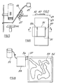
- Figures 1 to 4 illustrate a microscope viewing arrangement adapted for exhibition use comprising a console 11 enclosing a microscope arrangement 12 and affording a viewing position 13.
- the arrangement comprises remote focussing means 14 operable from the viewing position 13 and a lamp arrangement 15 adapted to illuminate a specimen position 16.
- the focussing means 14, the lamp arrangement 15 and the specimen position 16 are, in use, inaccessible from the viewing position.
- the arrangement also comprises information display means 17 adapted to display information relevant to a specimen mounted in the specimen position 16 and to be changed with such specimen.
- Specimen magazine means 18 are controlled from the viewing position 13 and comprise an indexable carousel arrangement 19 with clamps 21 for holding slides 22 in radially-extending fingers 23.
- the carousel arrangement has a slide setting position with a scale 24 by which a technician can accurately align a slide 22 in the carousel arrangement.
- Slides 22 for use in the arrangement have a strip of grip tape 25 for secure holding in the clamps 21.
- An indexing arrangement for the carousel 19 comprises a motor 26 rotating the carousel until a detent 27 engages an indexing notch 28 in the carousel.
- Indexing is controlled from a push button 29 in the console 11 which energises a solenoid 31 to retract the detent 27 and energises the motor 26 to rotate the carousel until the detent, with the solenoid 31 de-enegised once the motor 26 has started, drops back under a bias into the next notch 28, locating the carousel and de-enegising the motor 26.
- the detent arrangement could be replaced by an optical sensor and the motor 26 could be a stepper motor controlled by an integrated circuit arrangement under the control of a timing arrangement enabling the carousel to be indexed either automatically at set time intervals or manually by a console control which might override the automatic arrangement.
- the carousel 19 is mounted on a stage 32 which has movement in two orthogonal directions for moving the slide 22 relatively to the optical axis to view different areas thereof.
- the stage 32 movement is controlled from the viewing position 13 by a joystick arrangment 33 on the console 11 connected as by a pneumatic arrangement or electrically through stepping motors (not shown).
- a centering lamp (omitted for clarity′s sake) is mounted on the stage 32 to shine a spot of light, when switched on from the viewing position, at the centre of the slide. This enables the viewer rapidly to locate the centre of the slide in the viewed image for orientation purposes. The centering light is switched off once the centre has been found.
- the carousel 19 has a position transducer arrangement, illustrated diagrammatically at 34, which signals to an information display controller 35 to display information on the display 17 appropriate to whatever slide 22 is currently being viewed.
- the information display illustrated comprises panels 17a, 17b etc.... each of which has a transparency which is inserted by a technician setting up a particular display corresponding to the slide 22 for which such panel is selected. The controller then illuminates the appropriate panel 17a, 17b etc...
- a single panel could be used, with a set of transparencies arranged on a display carousel which is moved according to the movement of the slide carousel 19.
- Yet another arrangement would be to house a transparency mounted on the slide and to arrange that the transparency is projected on to the display 17 while the object on the slide 22 is being viewed.
- the information display could also be in the form of one or more video screens displaying alpha-numeric or graphics information from a computer memory, and such may be provided in different languages, selectable by a control on the console. Additionally or alternatively, high quality visual images could be displayed from video tape or even from a video disc arrangement which can be made interactive with the microscope arrangement.
- An editing facility can be provided to update information or change the display when the slides in the carousel are changed.
- the microscope is a projection microscope in which the slides 22 are viewed by transmitted light.
- the microscope lens 38 projects an image of the specimen already onto an inclined screen 39 at the viewing position 13, the image being trimmed to fit the rectangular screen 39 by a trapezoidal mask 41.
- Two lenses 38a, 38b are interchangeably mounted on the lens position, selectable from the console 11 for different magnification.
- Three or more such lenses could be provided, of course, selectable by a servo or stepping motor arrangement (not shown) or otherwise as convenient.
- a focussing arrangement is provided which includes a mechanical linkage 42 connected to a focussing control 43 in the console 11 for adjusting the position of the lenses 38a etc... along the optical path.
- An arrangement (not shown) can be provided for indicating at the viewing position, which magnification is in use - this can be generally similar to the arrangement which displays information in slide selection, but of course caters for much less information to be displayed.
- a zoom lens can of course be provided instead of (or even additionally to) fixed focus lenses. This can be selected in the same way as fixed focus lenses, if it is not the only lens provided, and its focal length and focussing can be controlled by stepper motors under microprocessor control. Pre-set focal length positions could be provided - a series of focal length buttons could be provided, depression of one of which would drive the zoom mechansim to the corresponding position.
- the lower (or lowest of three or more) magnification lens is selected automatically, or the zoom lens, if provided, is set to maximum focal length.
- filters e.g., polarising filters
- filters may be inserted selectively into the optical path on arrangements like this for lens changing.
- arrangements may be made for indicating at the viewing position which filter is in use.
- Arrangements may also be made for rotating polarising filters and indicating the angle of polarisation.
- Two polarising filters may be insertable in series, either side of the specimen position, to demonstrate the effect of crossed polarising filters, and to investigate substances which rotate the plane of polarisation.
- the viewer only has access to the front of the console 11, where the slide selection, magnification, focussing and positioning controls are situated. Access to the optics and the mechanical and electrical components can be had only from the back of console 11, which can be closed off from the front of the console, perhaps arranged in an adjacent room. It is clearly convenient if the technician can, while changing slides, also change the information to be displayed about them, from the rear of the console 11.
- a set of dual controls 10 is provided near the specimen position.
- Figure 3 illustrates a different arrangement adapted for viewing by reflected light, but also capable of viewing by transmitted light in which the viewing position 13 has a regular microscope eyepiece 44 and the carousel 19 is arranged beneath it.
- the carousel 19 is mounted on the moving stage 32 and is interconnected with the information display 17 to display information appropriate to the slide 22 positioned in the optical path.
- a projection arrangement could also, of course be accommodated with the projection arrangement being essentially upside down as compared to that desired with reference to Figures 1 and 2.
- a lamp arrangement 45 shines on to the slide 22 position in the optical path.
- a mirror 46 reflects light from the lamp arrangement 45 up through a slide 22 to be viewed by transmitted light.
- a number of microscope arrangements as illustrated in Figure 3 can be assembled in an ′island unit′ as shown in Figure 4. Again, access from the viewing position 13 is restricted to the slide selection, slide movement and focussing controls (only one magnification being permitted in this arrangement).
- Figure 9 illustrates a back projection arrangement in which the microscope projection unit 12, comprising lamp arrangement 15, carousel 19 and stage 32 as well as the lens arrangement 38, is mounted at the top of a low profile housing 91 and back projects an image on to a screen 92 via a mirror 93 located at the base of the housing 91.
- the screen 92 of course must be translucent to allow the back projected image to be viewed.
- FIG 10 shows how the housing illustrated in Figure 9 can be arranged in conjunction with other like housings in an exhibition or micrarium context.
- a row of housings 101 can be arranged to form alcoves 102 in which viewers may sit; two such rows are shown with an intervening passage 103 for service access.
- An "island" unit 104 is also illustrated. Service access for slide changing and maintenance is indicated by arrows, viewer positions by circles.
- Access to the mechanism for maintenance and slide and information-changing purposes is had either from a trap door arrangement or by moving out a ′wedge′ from the island unit comprising one of the microscope arrangements thereof.
- the crystal melting arrangements comprises a glass pipette 47 with a resistance wire 48 connected to a blower 49.
- the blower and current through the wire 48 are controlled by a console switch so that hot air can be blown on to the slide 22 to melt a crystal specimen therein, and, switched off, to cool the specimen to reform the crystals.
- Live specimens can be viewed using special slides 49 as shown in Figures 6 and 7 which house a low wall 51 of silicone rubber or like material which is permeable to air but not water.
- a microscope cover slip 52 forms a roof for the live specimen chamber and overhangs the edge of the slide 49 so that a droplet of water containing the live specimen can be introduced at the overhanging edge and then fill the chamber by capillary action. The open edge is then sealed off with a reversible angled metal strip 53.
- Figure 8 illustrates an ant's nest arrangement built on a base 54.
- a floor and ants′ ′runs′ 55 are fastened from a mixture of soil and resin glue, leading to a corner where is connected a tube 56 with a screw valve 57, the tube 56 being in turn connected to a feeding chamber 58 which can be supplied with syrup from a reservoir 59.
- Humidity is provided from a damp sponge beneath the nest base 54 and the nest is covered with a glass plate.
- the live specimen slides and the ants′ nest are, as before, contained within the region which is inaccessible to the viewer and which can only be accessed by the technician for maintenance or slide or specimen changing purposes. .
Landscapes
- Physics & Mathematics (AREA)
- Chemical & Material Sciences (AREA)
- Analytical Chemistry (AREA)
- General Physics & Mathematics (AREA)
- Optics & Photonics (AREA)
- Microscoopes, Condenser (AREA)
- Medicines Containing Antibodies Or Antigens For Use As Internal Diagnostic Agents (AREA)
- Investigating, Analyzing Materials By Fluorescence Or Luminescence (AREA)
- Analysing Materials By The Use Of Radiation (AREA)
Claims (18)
- Beobachtungsanordnung für ein Mikroskop, geeignet für die Verwendung in Ausstellungen mit einer Konsole (11), die eine Mikroskopanordnung (12), die in der Lage ist, ein Bild einer Probe an einer Beobachtungsposition (13) abzubilden, eine feingesteuerte Fokussiereinrichtung (14), die von der Beobachtungsposition (13) bedienbar ist, und eine Lampenanordnung (15) zur Beleuchtung einer in einer Probenmagazineinrichtung (18) in Position (16) gehaltenen Probe einschließt, wobei die Fokussiereinrichtung (14) die Lampenanordnung (15) und die Probenmagazineinrichtung (18) im Betrieb von der Beobachtungsposition (13) nicht zugänglich sind und mit einer Informations-Anzeigeeinrichtung (17), die zur Anzeige von Informationen geeignet ist, die die in der Probenmagazineinrichtung in Position (16) gehaltene Probe betreffen und mit einer solchen Probe zu ändern sind.
- Anordnung nach Anspruch 1, bei der die Probenmagazineinrichtung (18) von der Beobachtungsposition (13) gesteuert wird und dazu geeignet ist, eine Mehrzahl von Proben zu halten und sie individuell in die gehaltene Position (16) zu Positionieren.
- Anordnung nach Anspruch 2, bei der die Informations-Anzeigeeinrichtung (17) mit der Probenmagazineinrichtung (18) verbunden ist, wodurch die für jede individuelle Probe relevante Information anzeigbar ist, wenn sie in der gehaltenen Position (16) der Probenmagazineinrichtung (18) angeordnet ist.
- Anordnung nach einem der Ansprüche 1 bis 3, bei der die Konsole (11) eine Mehrzahl von Informationsfeldern (17a,17b...), von denen jedes geeignet ist, für eine Probe relevante Informationen zu enthalten, und eine Auswahlvorrichtung aufweist, die selektiv die Anzeigefelder beleuchtet.
- Anordnung nach Anspruch 4, die bei Verwendung mit der Probenmagazineinrichtung (18) geeignet ist, ein bestimmtes Informationsfeld beim Positionieren einer bestimmten Probe in die gehaltene Position (16) in der Probenmagazineinrichtung (18) zu beleuchten.
- Anordnung nach Anspruch 2, 3 oder 5, bei der die Probenmagazineinrichtung (18) eine einstellbare Karussellanordnung (19) und eine Indexvorrichtung (28) dafür umfaßt, die von der Konsole (11) bedienbar sind.
- Anordnung nach einem der Ansprüche 1 bis 6 mit einer Vergrößerungsänderungseinrichtung, durch die unterschiedliche Linsen (38a,38b) über eine Konsolensteuerung in den optischen Pfad positionierbar sind.
- Anordnung nach Anspruch 7 mit einer Linse, die von zwei geringere Vergrößerung oder von mehr als zwei Linsen die kleinste Vergrößerung der Vergrößerungsänderungseinrichtung vorgibt, die mit einer von der Konsole bedienbaren Probenwechselvorrichtung verbunden ist und die zur Auswahl der geringeren oder kleinsten Vergrößerungslinse bei Wechsel der Probe wirksam ist.
- Anordnung nach einem der Ansprüche 1 bis 8 mit einer transmittiertes Licht benutzenden Projektionsmikroskopanordnung (12), bei der die Lampenanordnung (15), die Mikroskopanordnung und die in Position gehaltene Probe in der Probenmagazineinrichtung (18) in einer zu der Konsole (11) erhöhten Stellung angeordnet sind, wobei das Mikroskop ein Bild der Probe nach unten auf den Beobachturgsschirm (92) projiziert.
- Anordnung nach einem der Ansprüche 1 bis 8 mit einer transmittiertes Licht benutzenden Projektionsmikroskopanordnung und einem Durchprojektionssystem, bei denen die Lampenanordnung, die Mikroskopanordnung und die in der Probenmagazineinrichtung (18) in Position (16) gehaltenen Probe hinter der Konsole (11) angeordnet sind, wobei das Mikroskop ein Bild der Probe nach oben über einen Spiegel (93) auf den Beobachtungsschirm (92) projiziert.
- Anordnung nach Anspruch 9 oder 10, bei der der Beobachtungsschirm auf einer Schräge angeordnet ist und eine Maske im optischen Pfad das Bild an den schrägen Beobachtungsschirm anpaßt.
- Anordnung nach einem der Ansprüche 1 bis 8 mit einer Mikroskopanordnung, deren Okular in der Konsole bei der Beobachtungsposition angeordnet ist.
- Anordnung nach Anspruch 11, bei der die Mikroskopanordnung als eine reflektiertes Licht benutzende Anordnung ausgebildet ist.
- Anordnung nach Anspruch 11 oder 12, bei der die Mikroskopanordnung als eine transmittiertes Licht benutzende Anordnung ausgebildet ist.
- Anordnung nach einem der Ansprüche 1 bis 13, die für die Beobachtung des Schmelzens und Bildung von Kristallen geeignet ist und eine von der Konsole bedienbare Warmluft-Düsenanordnung umfaßt, die warme Luft auf eine Kristallprobe in der gehaltenen Position der Probenmagazinanordnung richtet, um sie zu schmelzen.
- Anordnung nach einem der Ansprüche 1 bis 14 mit einer Kammer für lebende Proben, die einen Mikroskopobjektträger (49) mit einem Probenbereich, der von einer Wand (51) aus einem Sauerstoff durchlassenden, aber Wasser nicht durchlassenden Material umgeben ist und mit einem Deckstreifen (52) abgedeckt ist, umfaßt.
- Anordnung nach Anspruch 16, bei der die Wände nicht vollständig den Probenbereich umgeben und ein entfernbarer Verschluß vorgesehen ist.
- Anordnung nach einem der Ansprüche 1 bis 16 mit einer Kammer (58) für lebende Proben mit einer Nahrungs-, Wasser- und Luftversorgung für die Kammer.
Priority Applications (1)
| Application Number | Priority Date | Filing Date | Title |
|---|---|---|---|
| AT88308385T ATE87372T1 (de) | 1987-09-17 | 1988-09-12 | Beobachtungssystem fuer mikroskop. |
Applications Claiming Priority (2)
| Application Number | Priority Date | Filing Date | Title |
|---|---|---|---|
| GB8721878 | 1987-09-17 | ||
| GB878721878A GB8721878D0 (en) | 1987-09-17 | 1987-09-17 | Microscope viewing arrangements |
Publications (3)
| Publication Number | Publication Date |
|---|---|
| EP0308151A2 EP0308151A2 (de) | 1989-03-22 |
| EP0308151A3 EP0308151A3 (en) | 1989-11-08 |
| EP0308151B1 true EP0308151B1 (de) | 1993-03-24 |
Family
ID=10623935
Family Applications (1)
| Application Number | Title | Priority Date | Filing Date |
|---|---|---|---|
| EP88308385A Expired - Lifetime EP0308151B1 (de) | 1987-09-17 | 1988-09-12 | Beobachtungssystem für Mikroskop |
Country Status (9)
| Country | Link |
|---|---|
| US (1) | US5029996A (de) |
| EP (1) | EP0308151B1 (de) |
| JP (1) | JPH01157048A (de) |
| AT (1) | ATE87372T1 (de) |
| CA (1) | CA1313318C (de) |
| DE (1) | DE3879594T2 (de) |
| ES (1) | ES2040349T3 (de) |
| GB (2) | GB8721878D0 (de) |
| NZ (1) | NZ226241A (de) |
Families Citing this family (7)
| Publication number | Priority date | Publication date | Assignee | Title |
|---|---|---|---|---|
| DE4131360A1 (de) * | 1991-09-20 | 1993-03-25 | Jenoptik Jena Gmbh | Mikroskophandlingssystem |
| GB2273994A (en) * | 1992-12-18 | 1994-07-06 | Morphometrix Inc | Process microscopy system |
| US5768033A (en) * | 1996-06-14 | 1998-06-16 | Brock; Dennis | Microscope assembly comprising a supported and movable specimen wheel and fine adjustment means |
| AUPO084596A0 (en) * | 1996-07-04 | 1996-07-25 | University Of Technology, Sydney | Location and tracking system enhancements |
| KR20080033027A (ko) * | 2006-10-12 | 2008-04-16 | 최해용 | 교육용 실체 현미 영상 장치 |
| DE102008026978A1 (de) * | 2008-05-29 | 2009-12-03 | Carl Zeiss Ag | Fernrohr |
| GB2596597A (en) | 2020-07-03 | 2022-01-05 | Xrapid France Sas | Microscope apparatus |
Family Cites Families (20)
| Publication number | Priority date | Publication date | Assignee | Title |
|---|---|---|---|---|
| GB232793A (en) * | 1924-05-16 | 1925-04-30 | Vickers Ltd | Improvements in or relating to microscopes |
| GB788270A (en) * | 1955-01-26 | 1957-12-23 | Reichert Optische Werke Ag | Improvements in or relating to microscopes |
| FR1197111A (fr) * | 1956-01-15 | 1959-11-27 | Commissariat Energie Atomique | Installation et télécommande d'un microscope pour examen d'échantillons radioactifs |
| GB880708A (en) * | 1957-01-19 | 1961-10-25 | Reichert Optische Werke Ag | Apparatus for microscopic examination |
| FR1197952A (fr) * | 1958-01-18 | 1959-12-03 | Reichert Optische Werke Ag | Dispositif pour l'observation microscopique |
| US3319518A (en) * | 1965-02-17 | 1967-05-16 | Ncr Co | System for retrieving microimages formed on superpositioned microforms and the like |
| US3764215A (en) * | 1971-04-08 | 1973-10-09 | J Wallach | Apparatus and method for processing flexible medical slides |
| US3762798A (en) * | 1971-07-01 | 1973-10-02 | Hamilton Co | Microscope stage |
| GB1428732A (en) * | 1973-04-05 | 1976-03-17 | Nutritional Research Unit Ltd | Apparatus for displaying features having a predetermined parameter occurring within a particular field of an image |
| US4000417A (en) * | 1975-08-25 | 1976-12-28 | Honeywell Inc. | Scanning microscope system with automatic cell find and autofocus |
| DE2615841C3 (de) * | 1976-04-10 | 1978-10-19 | Fa. Carl Zeiss, 7920 Heidenheim | Verfahren zum automatischen Nachführen der Scharfeinstellung eines mit einer Fernsehkamera ausgerüsteten Mikroskops |
| JPS5714818A (en) * | 1980-06-30 | 1982-01-26 | Nippon Kogaku Kk <Nikon> | Reflection lighting type projector |
| US4405202A (en) * | 1981-03-30 | 1983-09-20 | Kimball Leonard L | Protective microscope container with remote control mechanism |
| US4453807A (en) * | 1981-06-17 | 1984-06-12 | Smithkline Beckman Corp | System for handling slides |
| JPS5971018A (ja) * | 1982-10-15 | 1984-04-21 | Ikegami Tsushinki Co Ltd | 自動顕微鏡装置 |
| NZ203838A (en) * | 1983-04-08 | 1988-02-12 | Donald Rivers Ensor | Inverted microscope |
| JPH0662305B2 (ja) * | 1983-12-29 | 1994-08-17 | オ−ストラリア国 | テクネチウム−99m−標識放射医薬の製造 |
| US4589741A (en) * | 1984-12-21 | 1986-05-20 | Clegg John E | Universal revolving microscope stage |
| JPS61270719A (ja) * | 1985-05-27 | 1986-12-01 | Mitsutoyo Mfg Corp | 顕微鏡 |
| JPS63152293A (ja) * | 1986-12-09 | 1988-06-24 | マイクロワ−ルド オブ インナ− スペ−ス リミテイド | 表示装置 |
-
1987
- 1987-09-17 GB GB878721878A patent/GB8721878D0/en active Pending
-
1988
- 1988-09-12 AT AT88308385T patent/ATE87372T1/de not_active IP Right Cessation
- 1988-09-12 ES ES198888308385T patent/ES2040349T3/es not_active Expired - Lifetime
- 1988-09-12 EP EP88308385A patent/EP0308151B1/de not_active Expired - Lifetime
- 1988-09-12 DE DE8888308385T patent/DE3879594T2/de not_active Expired - Fee Related
- 1988-09-12 GB GB8821376A patent/GB2210175B/en not_active Revoked
- 1988-09-16 US US07/245,270 patent/US5029996A/en not_active Expired - Fee Related
- 1988-09-16 CA CA000577656A patent/CA1313318C/en not_active Expired - Fee Related
- 1988-09-17 JP JP63231514A patent/JPH01157048A/ja active Pending
- 1988-09-19 NZ NZ226241A patent/NZ226241A/en unknown
Also Published As
| Publication number | Publication date |
|---|---|
| AU601623B2 (en) | 1990-09-13 |
| EP0308151A2 (de) | 1989-03-22 |
| GB2210175B (en) | 1991-10-09 |
| EP0308151A3 (en) | 1989-11-08 |
| CA1313318C (en) | 1993-02-02 |
| AU2223488A (en) | 1989-03-23 |
| ATE87372T1 (de) | 1993-04-15 |
| ES2040349T3 (es) | 1993-10-16 |
| DE3879594T2 (de) | 1993-09-09 |
| NZ226241A (en) | 1990-04-26 |
| DE3879594D1 (de) | 1993-04-29 |
| GB8821376D0 (en) | 1988-10-12 |
| GB8721878D0 (en) | 1987-10-21 |
| GB2210175A (en) | 1989-06-01 |
| JPH01157048A (ja) | 1989-06-20 |
| US5029996A (en) | 1991-07-09 |
Similar Documents
| Publication | Publication Date | Title |
|---|---|---|
| EP0121536B1 (de) | Filmvideowiedergabegerät | |
| US5090800A (en) | Projector having a liquid crystal display panel | |
| US6898004B2 (en) | Microscope system | |
| US4651200A (en) | Split-image, multi-power microscopic image display system and method | |
| US4769698A (en) | Interactive microscopic image display system and method | |
| US4673973A (en) | Split-image, multi-power microscopic image display system and method | |
| EP0308151B1 (de) | Beobachtungssystem für Mikroskop | |
| US4800404A (en) | Apparatus and method for testing visual sensitivity to glare | |
| US6804049B2 (en) | Microscope device and microscope system | |
| US7542202B2 (en) | Microscope and a controlling method thereof | |
| US4067648A (en) | Microfiche reader | |
| US3734593A (en) | Plural-microscope with light indicator | |
| JP2002516408A (ja) | 立体顕微鏡内ズームシステムの作動を直接的に制御するための装置 | |
| JPH07199077A (ja) | 顕微鏡システム | |
| US5024523A (en) | Map projection system | |
| US4526450A (en) | Eye fundus camera | |
| US3807846A (en) | Grid and co-ordinate location projection system | |
| US7116474B2 (en) | In vitro fertilization microscope | |
| GB2084754A (en) | Microscope | |
| USRE33883E (en) | Split-image multi-power microscopic image display system and method | |
| JP3246069B2 (ja) | 顕微鏡シミュレータ | |
| JPH02191909A (ja) | 機能設定装置を有する顕微鏡 | |
| GB2105859A (en) | Improvements in or relating to apparatus for viewing films | |
| JP2004003917A (ja) | 結晶観察方法及び装置 | |
| JPH0623823B2 (ja) | 地理情報の表示方法とその装置 |
Legal Events
| Date | Code | Title | Description |
|---|---|---|---|
| PUAI | Public reference made under article 153(3) epc to a published international application that has entered the european phase |
Free format text: ORIGINAL CODE: 0009012 |
|
| AK | Designated contracting states |
Kind code of ref document: A2 Designated state(s): AT BE CH DE ES FR GB GR IT LI LU NL SE |
|
| PUAL | Search report despatched |
Free format text: ORIGINAL CODE: 0009013 |
|
| AK | Designated contracting states |
Kind code of ref document: A3 Designated state(s): AT BE CH DE ES FR GB GR IT LI LU NL SE |
|
| 17P | Request for examination filed |
Effective date: 19891211 |
|
| 17Q | First examination report despatched |
Effective date: 19920116 |
|
| GRAA | (expected) grant |
Free format text: ORIGINAL CODE: 0009210 |
|
| AK | Designated contracting states |
Kind code of ref document: B1 Designated state(s): AT BE CH DE ES FR GB GR IT LI LU NL SE |
|
| PG25 | Lapsed in a contracting state [announced via postgrant information from national office to epo] |
Ref country code: GR Free format text: LAPSE BECAUSE OF FAILURE TO SUBMIT A TRANSLATION OF THE DESCRIPTION OR TO PAY THE FEE WITHIN THE PRESCRIBED TIME-LIMIT Effective date: 19930324 |
|
| REF | Corresponds to: |
Ref document number: 87372 Country of ref document: AT Date of ref document: 19930415 Kind code of ref document: T |
|
| REF | Corresponds to: |
Ref document number: 3879594 Country of ref document: DE Date of ref document: 19930429 |
|
| ITF | It: translation for a ep patent filed | ||
| ET | Fr: translation filed | ||
| REG | Reference to a national code |
Ref country code: ES Ref legal event code: FG2A Ref document number: 2040349 Country of ref document: ES Kind code of ref document: T3 |
|
| EPTA | Lu: last paid annual fee | ||
| PLBE | No opposition filed within time limit |
Free format text: ORIGINAL CODE: 0009261 |
|
| STAA | Information on the status of an ep patent application or granted ep patent |
Free format text: STATUS: NO OPPOSITION FILED WITHIN TIME LIMIT |
|
| 26N | No opposition filed | ||
| EAL | Se: european patent in force in sweden |
Ref document number: 88308385.9 |
|
| PGFP | Annual fee paid to national office [announced via postgrant information from national office to epo] |
Ref country code: FR Payment date: 19960808 Year of fee payment: 9 |
|
| PGFP | Annual fee paid to national office [announced via postgrant information from national office to epo] |
Ref country code: BE Payment date: 19960813 Year of fee payment: 9 |
|
| PGFP | Annual fee paid to national office [announced via postgrant information from national office to epo] |
Ref country code: SE Payment date: 19960814 Year of fee payment: 9 Ref country code: AT Payment date: 19960814 Year of fee payment: 9 |
|
| PGFP | Annual fee paid to national office [announced via postgrant information from national office to epo] |
Ref country code: DE Payment date: 19960826 Year of fee payment: 9 |
|
| PGFP | Annual fee paid to national office [announced via postgrant information from national office to epo] |
Ref country code: CH Payment date: 19960827 Year of fee payment: 9 |
|
| PGFP | Annual fee paid to national office [announced via postgrant information from national office to epo] |
Ref country code: NL Payment date: 19960830 Year of fee payment: 9 |
|
| PGFP | Annual fee paid to national office [announced via postgrant information from national office to epo] |
Ref country code: LU Payment date: 19960901 Year of fee payment: 9 |
|
| PGFP | Annual fee paid to national office [announced via postgrant information from national office to epo] |
Ref country code: ES Payment date: 19960912 Year of fee payment: 9 |
|
| PGFP | Annual fee paid to national office [announced via postgrant information from national office to epo] |
Ref country code: GB Payment date: 19970815 Year of fee payment: 10 |
|
| PG25 | Lapsed in a contracting state [announced via postgrant information from national office to epo] |
Ref country code: LU Free format text: LAPSE BECAUSE OF NON-PAYMENT OF DUE FEES Effective date: 19970912 Ref country code: AT Free format text: LAPSE BECAUSE OF NON-PAYMENT OF DUE FEES Effective date: 19970912 |
|
| PG25 | Lapsed in a contracting state [announced via postgrant information from national office to epo] |
Ref country code: SE Free format text: LAPSE BECAUSE OF NON-PAYMENT OF DUE FEES Effective date: 19970913 Ref country code: ES Free format text: LAPSE BECAUSE OF THE APPLICANT RENOUNCES Effective date: 19970913 |
|
| PG25 | Lapsed in a contracting state [announced via postgrant information from national office to epo] |
Ref country code: LI Free format text: LAPSE BECAUSE OF NON-PAYMENT OF DUE FEES Effective date: 19970930 Ref country code: FR Free format text: THE PATENT HAS BEEN ANNULLED BY A DECISION OF A NATIONAL AUTHORITY Effective date: 19970930 Ref country code: CH Free format text: LAPSE BECAUSE OF NON-PAYMENT OF DUE FEES Effective date: 19970930 Ref country code: BE Free format text: LAPSE BECAUSE OF NON-PAYMENT OF DUE FEES Effective date: 19970930 |
|
| BERE | Be: lapsed |
Owner name: BUXTON MICRARIUM LTD Effective date: 19970930 |
|
| PG25 | Lapsed in a contracting state [announced via postgrant information from national office to epo] |
Ref country code: NL Free format text: LAPSE BECAUSE OF NON-PAYMENT OF DUE FEES Effective date: 19980401 |
|
| REG | Reference to a national code |
Ref country code: CH Ref legal event code: PL |
|
| NLV4 | Nl: lapsed or anulled due to non-payment of the annual fee |
Effective date: 19980401 |
|
| PG25 | Lapsed in a contracting state [announced via postgrant information from national office to epo] |
Ref country code: DE Free format text: LAPSE BECAUSE OF NON-PAYMENT OF DUE FEES Effective date: 19980603 |
|
| EUG | Se: european patent has lapsed |
Ref document number: 88308385.9 |
|
| REG | Reference to a national code |
Ref country code: FR Ref legal event code: ST |
|
| PG25 | Lapsed in a contracting state [announced via postgrant information from national office to epo] |
Ref country code: GB Free format text: LAPSE BECAUSE OF NON-PAYMENT OF DUE FEES Effective date: 19980912 |
|
| GBPC | Gb: european patent ceased through non-payment of renewal fee |
Effective date: 19980912 |
|
| REG | Reference to a national code |
Ref country code: ES Ref legal event code: FD2A Effective date: 20001009 |
|
| PG25 | Lapsed in a contracting state [announced via postgrant information from national office to epo] |
Ref country code: IT Free format text: LAPSE BECAUSE OF NON-PAYMENT OF DUE FEES;WARNING: LAPSES OF ITALIAN PATENTS WITH EFFECTIVE DATE BEFORE 2007 MAY HAVE OCCURRED AT ANY TIME BEFORE 2007. THE CORRECT EFFECTIVE DATE MAY BE DIFFERENT FROM THE ONE RECORDED. Effective date: 20050912 |