EP0308256A2 - Achs- und Radeinheit - Google Patents
Achs- und Radeinheit Download PDFInfo
- Publication number
- EP0308256A2 EP0308256A2 EP88308613A EP88308613A EP0308256A2 EP 0308256 A2 EP0308256 A2 EP 0308256A2 EP 88308613 A EP88308613 A EP 88308613A EP 88308613 A EP88308613 A EP 88308613A EP 0308256 A2 EP0308256 A2 EP 0308256A2
- Authority
- EP
- European Patent Office
- Prior art keywords
- sealing
- lobes
- assembly
- rotatable
- hub member
- Prior art date
- Legal status (The legal status is an assumption and is not a legal conclusion. Google has not performed a legal analysis and makes no representation as to the accuracy of the status listed.)
- Granted
Links
- 238000007789 sealing Methods 0.000 claims abstract description 37
- 239000000428 dust Substances 0.000 description 2
- 230000000694 effects Effects 0.000 description 2
- 230000000712 assembly Effects 0.000 description 1
- 238000000429 assembly Methods 0.000 description 1
- 238000010276 construction Methods 0.000 description 1
- 239000013536 elastomeric material Substances 0.000 description 1
- 239000012530 fluid Substances 0.000 description 1
- 230000004048 modification Effects 0.000 description 1
- 238000012986 modification Methods 0.000 description 1
- 230000002028 premature Effects 0.000 description 1
- 238000011144 upstream manufacturing Methods 0.000 description 1
Images

Classifications
-
- F—MECHANICAL ENGINEERING; LIGHTING; HEATING; WEAPONS; BLASTING
- F16—ENGINEERING ELEMENTS AND UNITS; GENERAL MEASURES FOR PRODUCING AND MAINTAINING EFFECTIVE FUNCTIONING OF MACHINES OR INSTALLATIONS; THERMAL INSULATION IN GENERAL
- F16J—PISTONS; CYLINDERS; SEALINGS
- F16J15/00—Sealings
- F16J15/54—Other sealings for rotating shafts
-
- B—PERFORMING OPERATIONS; TRANSPORTING
- B60—VEHICLES IN GENERAL
- B60C—VEHICLE TYRES; TYRE INFLATION; TYRE CHANGING; CONNECTING VALVES TO INFLATABLE ELASTIC BODIES IN GENERAL; DEVICES OR ARRANGEMENTS RELATED TO TYRES
- B60C23/00—Devices for measuring, signalling, controlling, or distributing tyre pressure or temperature, specially adapted for mounting on vehicles; Arrangement of tyre inflating devices on vehicles, e.g. of pumps or of tanks; Tyre cooling arrangements
- B60C23/001—Devices for manually or automatically controlling or distributing tyre pressure whilst the vehicle is moving
- B60C23/003—Devices for manually or automatically controlling or distributing tyre pressure whilst the vehicle is moving comprising rotational joints between vehicle-mounted pressure sources and the tyres
- B60C23/00363—Details of sealings
-
- B—PERFORMING OPERATIONS; TRANSPORTING
- B60—VEHICLES IN GENERAL
- B60C—VEHICLE TYRES; TYRE INFLATION; TYRE CHANGING; CONNECTING VALVES TO INFLATABLE ELASTIC BODIES IN GENERAL; DEVICES OR ARRANGEMENTS RELATED TO TYRES
- B60C23/00—Devices for measuring, signalling, controlling, or distributing tyre pressure or temperature, specially adapted for mounting on vehicles; Arrangement of tyre inflating devices on vehicles, e.g. of pumps or of tanks; Tyre cooling arrangements
- B60C23/001—Devices for manually or automatically controlling or distributing tyre pressure whilst the vehicle is moving
- B60C23/003—Devices for manually or automatically controlling or distributing tyre pressure whilst the vehicle is moving comprising rotational joints between vehicle-mounted pressure sources and the tyres
- B60C23/00309—Devices for manually or automatically controlling or distributing tyre pressure whilst the vehicle is moving comprising rotational joints between vehicle-mounted pressure sources and the tyres characterised by the location of the components, e.g. valves, sealings, conduits or sensors
- B60C23/00318—Devices for manually or automatically controlling or distributing tyre pressure whilst the vehicle is moving comprising rotational joints between vehicle-mounted pressure sources and the tyres characterised by the location of the components, e.g. valves, sealings, conduits or sensors on the wheels or the hubs
-
- B—PERFORMING OPERATIONS; TRANSPORTING
- B60—VEHICLES IN GENERAL
- B60C—VEHICLE TYRES; TYRE INFLATION; TYRE CHANGING; CONNECTING VALVES TO INFLATABLE ELASTIC BODIES IN GENERAL; DEVICES OR ARRANGEMENTS RELATED TO TYRES
- B60C23/00—Devices for measuring, signalling, controlling, or distributing tyre pressure or temperature, specially adapted for mounting on vehicles; Arrangement of tyre inflating devices on vehicles, e.g. of pumps or of tanks; Tyre cooling arrangements
- B60C23/001—Devices for manually or automatically controlling or distributing tyre pressure whilst the vehicle is moving
- B60C23/003—Devices for manually or automatically controlling or distributing tyre pressure whilst the vehicle is moving comprising rotational joints between vehicle-mounted pressure sources and the tyres
- B60C23/00345—Details of the rotational joints
-
- Y—GENERAL TAGGING OF NEW TECHNOLOGICAL DEVELOPMENTS; GENERAL TAGGING OF CROSS-SECTIONAL TECHNOLOGIES SPANNING OVER SEVERAL SECTIONS OF THE IPC; TECHNICAL SUBJECTS COVERED BY FORMER USPC CROSS-REFERENCE ART COLLECTIONS [XRACs] AND DIGESTS
- Y10—TECHNICAL SUBJECTS COVERED BY FORMER USPC
- Y10T—TECHNICAL SUBJECTS COVERED BY FORMER US CLASSIFICATION
- Y10T137/00—Fluid handling
- Y10T137/8593—Systems
- Y10T137/86268—With running joint between movable parts of system
Definitions
- This invention relates to an axle and wheel assembly and, more particularly to an axle and wheel assembly for vehicles having an onboard tire inflation system having a rotary seal assembly for sealing passages between a rotatable and non-rotatable member of the axle and wheel assembly.
- U.S. Patents 3,705,614, 4,431,4043, 4,434,833 and 4,498,709 disclose axle and wheel assemblies having a rotary seal assembly including one or more annular rubber rings or the like which are in sealing engagement with a rotary member at all times, whether or not pressurized air is present. Thus, the lips are continuously in sealing engagement with the rotary members and subject to wear and possible premature failure.
- U.S. Patent 3,362,452 discloses a seal for an axle and wheel assembly which includes an annular seal assembly having resilient seal means extendible axially, when pressurized, into sealing engagement with a radial surface on the wheel hub.
- the seal assembly seals a chamber in the wheel hub which has an outlet to the tire.
- on board tire inflation system as used herein is intended to include systems mounted on vehicles which allow tire pressure of certain axle ends to be selectively varied by the operator from a point remote from the wheels, usually the cab, from an on board source of pressurized fluid, usually the vehicle air system and or stored compressed air.
- inboard is used to mean the direction axially toward the center of an axle assembly while the term “outboard” is used to mean the direction axially away from the center of an axle assembly.
- Fig. 1 of the drawing illustrates the invention in connection with a vehicle having a rear drive axle generally referred to by the numeral 10.
- the tubular axle housing 11 is suitably supported on the chassis of the vehicle and has an outboard spindle end 13 upon which tapered roller bearings 14 and 15 are received.
- a wheel hub 16 surrounds the spindle 13 and is rotatably supported on the bearings 14 and 15.
- An axle shaft 17 is rotatably received within the axle housing 11 and includes an outboard flange portion 18 which is fixed to the wheel hub 16 by means of bolts 19 for establishing a driving relationship between the axle shaft 17 and the hub 16.
- a tire and wheel assembly (not shown) is attached to a radially extending flange portion 20 of hub 16.
- the wheel hub 16 includes an annular axially extending portion 21 which extends inwardly from the inboard bearing 15.
- the portion 21 has an annular inner sealing surface 22 which is generally concentric with and of greater diameter than the seal assembly 23.
- An annular groove 24 is formed in the inner surface 21 and includes an outlet 25 to the passageway 26 extending axially through the hub 16 and terminates in an outlet 27 suitably connected by a conduit 28 which is in turn connected to the rim of the tire mounted on the wheel (not shown).
- a non-rotatable air inlet member 29 is mounted on the axle housing 11 adjacent the inboard bearing 15.
- the inboard end 30 of the member 29 is provided with an air inlet 31 communicating with a passageway 32 which terminates in an air outlet 33 in the form of an annular groove.
- the outlet 33 is formed in the radially outer inboard surface 34 of the member 29 and is located generally in radial alignment with the groove 24.
- the seal assembly 23 seals the inboard surface 34 of the member 29 and the inner surface 22 of the wheel hub 16 so that pressurized air may pass from the outlet 33 through the seal assembly to the outlet 25 through the passageway 26 and hence to the tire without loss of air.
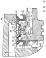
- the seal assembly 23, as shown in Fig. 2, includes a rigid annular rim member 35 having a flange 36 connected by suitable fasteners 37 to the inboard end 30 of the member 29.
- a pair of O rings 38 are provided, one on each side of the outlet 33 to seal the radially inner surface 39 of the rim member 35.
- a plurality of outlet holes 40 are formed in the member 35 in radial alignment with the outlet 33.
- a pair of annular rigid uprights 41 and 42 are welded or otherwise secured at 43 to the member 35, each of which has an axially extending hole 44 circumferentially aligned with the outlet holes 40.
- Each of the uprights 41 and 42 have a pair of annular flanges 45 which are pressed or clamped to the annular ends 46 of the inflatable sealing bladders 47 made of rubber-like or elastomeric material.
- the opposite ends 48 of the bladders 47 each have an L shaped annular rigid member 49 embedded thereon to provide rigidity to the ends 48 and thus seal the ends 48 to the rim member 35.
- Each of the bladders 47 is provided with a bulbous shaped lobe 50 at the radially outer circumference which, upon pressurization of the bladders, expand radially and form an air tight seal against the surfaces 22 of the hub adjacent both sides of the groove 24 and outlet 25.
- the lobes ride very lightly, if at all, against the surfaces 22 and do not form a seal.
- each of the bladders is provided with one or more dust tabs 51 which bear against the surfaces 22 adjacent the groove 24 to prevent dust and other debris from entering the space between the lobes 50 and from reaching the sealing surfaces 22.
- the radially outer surface 52 of the uprights 41 and 42 extends continuously and circumferentially.
- One or more holes 53 are formed in the radially outward surface 52.
- Check valves 54 are provided with a large head 55 which seals against the perphiphy of the holes 53 and a smaller head 56 is provided at the opposite end of the valve.
- a spring 57 is interposed between the head 56 and the undersurface of the valve seat so that the valve is normally in closed position and seals the holes 53.
- the seal assembly 23 is depressurized initially, as shown in Fig. 2, and the valves 54 are in their normally closed position.
- the lobes 50 bear against the surfaces 22 with very light if any pressure and not in sealing relationship with the surfaces 22.
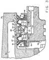
- pressurized air is admitted through the air inlet 31 from a compressed air source on the vehicle and passes through the outlet 40 and the holes 44 in the uprights to pressurize the bladders and particularly the lobes 50. Pressurization of the lobes continues until the pressure therein exceeds the force required to compress the spring 57, at which time the check valves 54 open and permits air to flow into the tire, as shown in Fig. 3.
- the valves 54 open the pressure in each of the lobes 50 is sufficient to effect an air tight seal against the surfaces 22.
- the air tight seal against the surfaces 22 is effective whether the wheel and the hub 16 is stationery or rotating relative to the non-rotatable member 29.
- a suitable check valve (not shown) is provided in the air circuit to the tire upstream from the passageway 26 to keep the tire pressurized at the increased pressure.
- the air inlet 31 is connected to exhaust or atmospheric pressure thereby depressurizing the seal assembly 23 and causing the valves 54 to close, at which time the lobes 50 return to the position shown in Fig. 2. It is thus seen that the seal assembly 23 effects a seal against the surfaces 22 only "on demand" or when air pressure is being injected into the tire.
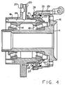
- Fig. 4 another modification of the invention is shown in which the seal assembly 23 is positioned radially outwardly of the wheel hub 16 which may be desireable in the front wheel steering axle of a vehicle having a central tire inflation system.
- the flange 36 of the rim member 35 is attached by bolts 37 to the inboard end of the non-rotatable air inlet member 29 which is provided with a radially flange 59 attached by bolts 60 to the flange 61 of the non-rotatable axle spindle or housing 11.
- the lobes 50 expand radially inwardly when pressurized, and seal against the sealing surfaces 22 formed on the radially outer surface of the wheel hub portion 21.
- the construction and operation of the embodiment of the invention shown in Fig. 4 is otherwise similar to that shown in Fig. 1, except that the lobes 50 are supported by non-rotatable member 29 and expand radially inwardly against the rotating sealing surfaces 22 of the wheel hub 16.
- sealing lobes 50 are expandable radially in either an outward direction as shown in Figs. 1, 2 and 3, or in a radially inward direction as shown in Fig. 4.
- the lobes 50 expand radially and seal against cylindrical sealing surfaces.
- the seal is formed only "on demand” or when it is necessary that a seal be made, namely, when air is to be injected into the tire.
Landscapes
- Engineering & Computer Science (AREA)
- Mechanical Engineering (AREA)
- General Engineering & Computer Science (AREA)
- Check Valves (AREA)
- Tires In General (AREA)
- Steering-Linkage Mechanisms And Four-Wheel Steering (AREA)
- Seal Device For Vehicle (AREA)
- Vehicle Body Suspensions (AREA)
Priority Applications (1)
| Application Number | Priority Date | Filing Date | Title |
|---|---|---|---|
| AT88308613T ATE70783T1 (de) | 1987-09-17 | 1988-09-16 | Achs- und radeinheit. |
Applications Claiming Priority (2)
| Application Number | Priority Date | Filing Date | Title |
|---|---|---|---|
| US07/098,343 US4804027A (en) | 1987-09-17 | 1987-09-17 | Axle and wheel assembly |
| US98343 | 1987-09-17 |
Publications (3)
| Publication Number | Publication Date |
|---|---|
| EP0308256A2 true EP0308256A2 (de) | 1989-03-22 |
| EP0308256A3 EP0308256A3 (en) | 1989-05-31 |
| EP0308256B1 EP0308256B1 (de) | 1991-12-27 |
Family
ID=22268866
Family Applications (1)
| Application Number | Title | Priority Date | Filing Date |
|---|---|---|---|
| EP88308613A Expired - Lifetime EP0308256B1 (de) | 1987-09-17 | 1988-09-16 | Achs- und Radeinheit |
Country Status (8)
| Country | Link |
|---|---|
| US (1) | US4804027A (de) |
| EP (1) | EP0308256B1 (de) |
| JP (1) | JPH01109103A (de) |
| KR (1) | KR910005637B1 (de) |
| AT (1) | ATE70783T1 (de) |
| CA (1) | CA1286579C (de) |
| DE (1) | DE3867191D1 (de) |
| ES (1) | ES2028293T3 (de) |
Cited By (5)
| Publication number | Priority date | Publication date | Assignee | Title |
|---|---|---|---|---|
| EP0410723A1 (de) * | 1989-07-28 | 1991-01-30 | Keeper Co. Ltd | Dichtvorrichtung für eine Reifendruckregelungsanlage |
| EP0480855A1 (de) * | 1990-10-12 | 1992-04-15 | Stéphane Fazekas | Übertragungseinrichtung für ein Fluid unter relativem Druck mit Hilfe einer Druckregeleinrichtung eines während der Fahrt aufblasbaren Reifens |
| EP1147925A3 (de) * | 2000-04-19 | 2003-06-18 | Carl Freudenberg KG | Dichtungsanordnung |
| EP2308698A3 (de) * | 2009-10-08 | 2011-09-14 | CLAAS Industrietechnik GmbH | Reifendruck-Regelanlage mit Drehdurchführung und Ventilbaugruppe |
| DE102018101411B4 (de) | 2018-01-23 | 2024-10-17 | Schaeffler Technologies AG & Co. KG | Dichtungsanordnung für eine Drehdurchführung eines Radlager eines Kraftfahrzeugs |
Families Citing this family (46)
| Publication number | Priority date | Publication date | Assignee | Title |
|---|---|---|---|---|
| US5080156A (en) * | 1990-02-12 | 1992-01-14 | Bartos Josef A | Vehicle wheel and axle assembly for controlling air pressure in tires with spaces between the bearing elements and the race members included in the air flow path |
| US5174839A (en) * | 1991-07-05 | 1992-12-29 | Eaton Corporation | Drive axle sleeve and seal assembly |
| US5180456A (en) * | 1991-11-15 | 1993-01-19 | Eaton Corporation | Adaptive inflation control for vehicle central tire inflation system |
| EP0588595A1 (de) * | 1992-09-15 | 1994-03-23 | Oshkosh Truck Corporation | Zentral-Reifendruckfülleinrichtung für originalen oder nachträglichen Einbau |
| US5429167A (en) * | 1993-08-13 | 1995-07-04 | Oshkosh Truck Corporation | Universal central tire inflation system for trailers |
| JPH0821540A (ja) * | 1994-07-04 | 1996-01-23 | Yazaki Corp | ロータリバルブ |
| US5516379A (en) | 1994-10-20 | 1996-05-14 | Eaton Corporation | CTI program pressure setting override |
| US5544688A (en) | 1994-12-23 | 1996-08-13 | Eaton Corporation | Two stage kneeling valve |
| FR2750082A1 (fr) * | 1996-06-25 | 1997-12-26 | Michelin & Cie | Ensemble moyeu et porte-moyeu pour vehicule equipe d'un systeme de gonflage centralise |
| AT2364U1 (de) | 1997-09-09 | 1998-09-25 | Steyr Daimler Puch Ag | Radträger für kraftfahrzeug mit reifenfüllanlage |
| DE19757000C1 (de) * | 1997-12-20 | 1999-08-05 | Zahnradfabrik Friedrichshafen | Luftdurchführung zur Reifendruckregelung |
| US6246317B1 (en) | 1998-02-27 | 2001-06-12 | William Pickornik | Target pressure learn strategy for vehicular tire pressure systems |
| US6145558A (en) * | 1998-12-10 | 2000-11-14 | Case Corporation | Seal arrangement for a central tire inflation system |
| US6325123B1 (en) * | 1999-12-23 | 2001-12-04 | Dana Corporation | Tire inflation system for a steering knuckle wheel end |
| US6402258B1 (en) | 2000-03-06 | 2002-06-11 | Augusto H. Martinez | Vehicle wheel attachment system |
| DE10044885B4 (de) * | 2000-09-12 | 2004-08-05 | Gkn Walterscheid Gmbh | Vorrichtung zum Befüllen oder Entlüften des Reifens eines Fahrzeuges, insbesondere eines Traktors |
| DE10208024B4 (de) | 2002-02-26 | 2005-06-02 | Gkn Walterscheid Gmbh | Drehdurchführung für eine Vorrichtung zum Füllen oder Entlüften eines Reifens eines Traktorrades |
| DE10302444B4 (de) * | 2003-01-21 | 2006-05-18 | Gkn Walterscheid Gmbh | Radlagerung für ein Fahrzeugrad |
| NL1024411C2 (nl) * | 2003-09-30 | 2005-03-31 | Skf Ab | Lagereenheid voor een voertuignaaf met concentrische naafsecties. |
| DE102006006143A1 (de) * | 2006-02-10 | 2007-08-23 | Schaeffler Kg | Dichtungsanordnung für eine Reifendruck-Reguliereinrichtung |
| DE602006005480D1 (de) * | 2006-07-11 | 2009-04-16 | Skf Ab | Lagervorrichtung für eine Radnabe um Druckluft an einen Fahrzeugreifen zu liefern |
| US7931061B2 (en) * | 2008-12-15 | 2011-04-26 | Arvinmeritor Technology, Llc | Tire inflation system with integrated wheel seal |
| JP5682867B2 (ja) * | 2009-09-29 | 2015-03-11 | Ntn株式会社 | 密封型転がり軸受 |
| GB201021931D0 (en) * | 2010-12-23 | 2011-02-02 | Agco Int Gmbh | Rotary seal arrangement |
| DE102011104760A1 (de) | 2011-06-18 | 2012-12-20 | Wabco Gmbh | Drucksteuereinrichtung für eine Reifenfüllanlage mit Drehdurchführung, Drehdurchführung, Reifenfüllanlage, Kraftfahrzeug mit Reifenfüllanlage und Reifendruckänderungsverfahren |
| US9126460B2 (en) | 2012-03-02 | 2015-09-08 | Dana Heavy Vehicle Systems Group, Llc | Tire inflation system having a sleeve shaped air passage |
| EP2834091B1 (de) | 2012-04-06 | 2019-08-28 | Dana Heavy Vehicle Systems Group, LLC | Reifenfüllanlage |
| US10059156B2 (en) | 2012-04-09 | 2018-08-28 | Dana Heavy Vehicle Systems Group, Llc | Hub assembly for a tire inflation system |
| EP2836376B1 (de) | 2012-04-09 | 2020-03-04 | Dana Heavy Vehicle Systems Group, LLC | Reifenfüllanlage |
| DK2888119T3 (da) * | 2012-08-20 | 2019-07-08 | Ice Adaptive Tires Llc | Dæksystem, som kan tilpasses is |
| DE102012217040A1 (de) * | 2012-09-21 | 2014-03-27 | Schaeffler Technologies Gmbh & Co. Kg | Luftführungsanordnung zur Reifendruck-Regulierung |
| AU2013336975B2 (en) * | 2012-10-26 | 2017-06-29 | Gv Engineering Gmbh | Vehicle axle assembly comprising integrated pressure medium line for filling tyres |
| DE102013105890A1 (de) * | 2013-06-07 | 2014-12-11 | Claas Selbstfahrende Erntemaschinen Gmbh | Drehdurchführung |
| GB201315426D0 (en) | 2013-08-29 | 2013-10-16 | Agco Int Gmbh | Tyre inflation control arrangement |
| US9162539B2 (en) | 2014-01-24 | 2015-10-20 | American Axle & Manufacturing, Inc. | Axle assembly having wheel hubs configured for use in vehicle with central tire inflation system |
| WO2015195998A1 (en) | 2014-06-20 | 2015-12-23 | Dana Heavy Vehicle Systems Group, Llc | Rotary joint assembly |
| US9511635B2 (en) * | 2014-07-10 | 2016-12-06 | Airgo Ip, Llc | Apparatus for delivering air through powered axle assemblies |
| DE112016004794T5 (de) | 2015-10-20 | 2018-07-19 | Dana Heavy Vehicle Systems Group, Llc | Radanschlussanordnung für ein reifendruckregelsystem und damit hergestelltes reifendruckregelsystem |
| EP3318427A1 (de) * | 2016-11-04 | 2018-05-09 | DANA ITALIA S.r.l. | Drehkupplungsanordnung für ein reifenfüllsystem |
| US11292300B2 (en) | 2017-01-17 | 2022-04-05 | Dana Automotive Systems Group, Llc | Ported wheel hub assembly and the tire inflation system made therewith |
| PL3401129T3 (pl) * | 2017-05-12 | 2019-12-31 | Reinhold Schulte | Urządzenie do zapewniania ciśnienia w oponach |
| US11077726B2 (en) * | 2017-06-30 | 2021-08-03 | Dana Automotive Systems Group, Llc | Front axle rotary joint assembly and the tire inflation system made therewith |
| IT201900018323A1 (it) * | 2019-10-09 | 2021-04-09 | Italian Tecnology 2018 S R L | Giunto rotante |
| WO2022130423A1 (en) | 2020-12-18 | 2022-06-23 | Italian Technology 2018 S.R.L. | Rotating joint |
| AU2023324834A1 (en) * | 2022-08-19 | 2025-02-27 | Consolidated Metco, Inc. | Wheel hub with passageway |
| CA3264089A1 (en) * | 2022-08-19 | 2024-02-22 | Consolidated Metco, Inc. | Tire inflation system |
Family Cites Families (8)
| Publication number | Priority date | Publication date | Assignee | Title |
|---|---|---|---|---|
| US3330563A (en) * | 1965-07-15 | 1967-07-11 | Dico Corp | Inflatable seal structure |
| US3362452A (en) * | 1966-07-27 | 1968-01-09 | Bendix Corp | Aircraft tire inflation-deflation system |
| SE397575B (sv) * | 1976-02-18 | 1977-11-07 | Stal Refrigeration Ab | Sett och anordning for att forhindra fastfrysning av ett anslutningsdon for ett kallt gasformigt medium |
| SE416190B (sv) * | 1979-03-12 | 1980-12-08 | Stal Refrigeration Ab | Anslutningsdon for att ansluta en oppning hos en flyttbar lastbehallare till en luftkonditioneringsanleggning |
| DE3266850D1 (en) * | 1981-09-25 | 1985-11-14 | Rieter Ag Maschf | Device for conveying a fluid under pressure to a shaft |
| US4434833A (en) * | 1982-04-21 | 1984-03-06 | Eaton Corporation | Axle wheel end assembly |
| US4730656A (en) * | 1985-07-08 | 1988-03-15 | Am General Corporation | Vehicle wheel end assembly |
| FR2604398B1 (fr) * | 1986-09-30 | 1989-03-03 | Peugeot | Circuit de passage d'air pour un dispositif de gonflage automatique d'une roue de vehicule |
-
1987
- 1987-09-17 US US07/098,343 patent/US4804027A/en not_active Expired - Fee Related
-
1988
- 1988-07-27 CA CA 573210 patent/CA1286579C/en not_active Expired - Lifetime
- 1988-08-29 KR KR1019880010984A patent/KR910005637B1/ko not_active Expired
- 1988-09-16 EP EP88308613A patent/EP0308256B1/de not_active Expired - Lifetime
- 1988-09-16 DE DE8888308613T patent/DE3867191D1/de not_active Expired - Lifetime
- 1988-09-16 ES ES88308613T patent/ES2028293T3/es not_active Expired - Lifetime
- 1988-09-16 AT AT88308613T patent/ATE70783T1/de not_active IP Right Cessation
- 1988-09-17 JP JP63233382A patent/JPH01109103A/ja active Pending
Cited By (7)
| Publication number | Priority date | Publication date | Assignee | Title |
|---|---|---|---|---|
| EP0410723A1 (de) * | 1989-07-28 | 1991-01-30 | Keeper Co. Ltd | Dichtvorrichtung für eine Reifendruckregelungsanlage |
| US5147494A (en) * | 1989-07-28 | 1992-09-15 | Keeper Co., Ltd. | Seal device for tire pressure-adjusting device |
| EP0480855A1 (de) * | 1990-10-12 | 1992-04-15 | Stéphane Fazekas | Übertragungseinrichtung für ein Fluid unter relativem Druck mit Hilfe einer Druckregeleinrichtung eines während der Fahrt aufblasbaren Reifens |
| FR2667826A1 (fr) * | 1990-10-12 | 1992-04-17 | Fazekas Stephane | Dispositif de transfert de fluide sous pression relative dans une installation de regulation de la pression de gonflage d'un pneumatique de vehicule roulant. |
| EP1147925A3 (de) * | 2000-04-19 | 2003-06-18 | Carl Freudenberg KG | Dichtungsanordnung |
| EP2308698A3 (de) * | 2009-10-08 | 2011-09-14 | CLAAS Industrietechnik GmbH | Reifendruck-Regelanlage mit Drehdurchführung und Ventilbaugruppe |
| DE102018101411B4 (de) | 2018-01-23 | 2024-10-17 | Schaeffler Technologies AG & Co. KG | Dichtungsanordnung für eine Drehdurchführung eines Radlager eines Kraftfahrzeugs |
Also Published As
| Publication number | Publication date |
|---|---|
| KR890005432A (ko) | 1989-05-15 |
| DE3867191D1 (de) | 1992-02-06 |
| EP0308256B1 (de) | 1991-12-27 |
| ATE70783T1 (de) | 1992-01-15 |
| KR910005637B1 (ko) | 1991-08-01 |
| JPH01109103A (ja) | 1989-04-26 |
| CA1286579C (en) | 1991-07-23 |
| ES2028293T3 (es) | 1992-07-01 |
| EP0308256A3 (en) | 1989-05-31 |
| US4804027A (en) | 1989-02-14 |
Similar Documents
| Publication | Publication Date | Title |
|---|---|---|
| US4804027A (en) | Axle and wheel assembly | |
| US5080156A (en) | Vehicle wheel and axle assembly for controlling air pressure in tires with spaces between the bearing elements and the race members included in the air flow path | |
| US4733707A (en) | Vehicle wheel end assembly | |
| US4685501A (en) | Remotely controlled inflation/deflation valve system for a vehicle tire | |
| US4582107A (en) | Vehicle tire inflation-deflation mechanism | |
| US5979526A (en) | Hub and hub-holder assembly for vehicles equipped with a central tire inflation system | |
| US4434833A (en) | Axle wheel end assembly | |
| US5398743A (en) | Tire inflating and deflating system | |
| US6363985B1 (en) | Rotary air coupling for tire inflation system | |
| US4922984A (en) | Inflation and deflation of a tire in rotation | |
| US4498515A (en) | Onboard tire inflation system | |
| US7117909B2 (en) | Expandable spindle plug assembly for use with automatic tire inflation systems | |
| JPH06507860A (ja) | 圧力調整システムを備えた車輪装着装置 | |
| US6182727B1 (en) | Rotary air coupling for tire inflation system | |
| US1800780A (en) | Means for inflating pneumatic tires | |
| CN103079843A (zh) | 胎压控制设备及其回转接头 | |
| US20100065177A1 (en) | Wheel axle and drive or universal shaft for vehicles with a central tyre pressure supply | |
| CA2332294A1 (en) | Rotary union for air inflation system | |
| JPH0377083B2 (de) | ||
| RU2761312C2 (ru) | Вращающееся соединение и система регулирования давления для шин | |
| US11292300B2 (en) | Ported wheel hub assembly and the tire inflation system made therewith | |
| CN116409095B (zh) | 具有主轴塞和套筒的车桥组件 | |
| US4917163A (en) | Rapid tire deflation system | |
| US20050236083A1 (en) | Vehicle wheel assembly with a hollow stud and internal passageways connected to a CTIS | |
| EP0362921B1 (de) | Ein an einen Wälzlager angeordneter Dichtungsring zur Verbindung von zwei Fluidbehältern mit unterschiedlichem Druck, wobei wenigstens einer bezüglich des anderen drehbar ist |
Legal Events
| Date | Code | Title | Description |
|---|---|---|---|
| PUAI | Public reference made under article 153(3) epc to a published international application that has entered the european phase |
Free format text: ORIGINAL CODE: 0009012 |
|
| AK | Designated contracting states |
Kind code of ref document: A2 Designated state(s): AT CH DE ES FR GB IT LI NL SE |
|
| PUAL | Search report despatched |
Free format text: ORIGINAL CODE: 0009013 |
|
| AK | Designated contracting states |
Kind code of ref document: A3 Designated state(s): AT CH DE ES FR GB IT LI NL SE |
|
| 17P | Request for examination filed |
Effective date: 19891123 |
|
| 17Q | First examination report despatched |
Effective date: 19900906 |
|
| GRAA | (expected) grant |
Free format text: ORIGINAL CODE: 0009210 |
|
| AK | Designated contracting states |
Kind code of ref document: B1 Designated state(s): AT CH DE ES FR GB IT LI NL SE |
|
| REF | Corresponds to: |
Ref document number: 70783 Country of ref document: AT Date of ref document: 19920115 Kind code of ref document: T |
|
| ITF | It: translation for a ep patent filed | ||
| REF | Corresponds to: |
Ref document number: 3867191 Country of ref document: DE Date of ref document: 19920206 |
|
| ET | Fr: translation filed | ||
| REG | Reference to a national code |
Ref country code: ES Ref legal event code: FG2A Ref document number: 2028293 Country of ref document: ES Kind code of ref document: T3 |
|
| PLBE | No opposition filed within time limit |
Free format text: ORIGINAL CODE: 0009261 |
|
| STAA | Information on the status of an ep patent application or granted ep patent |
Free format text: STATUS: NO OPPOSITION FILED WITHIN TIME LIMIT |
|
| 26N | No opposition filed | ||
| EAL | Se: european patent in force in sweden |
Ref document number: 88308613.4 |
|
| PGFP | Annual fee paid to national office [announced via postgrant information from national office to epo] |
Ref country code: NL Payment date: 19950707 Year of fee payment: 8 |
|
| PGFP | Annual fee paid to national office [announced via postgrant information from national office to epo] |
Ref country code: GB Payment date: 19950807 Year of fee payment: 8 |
|
| PGFP | Annual fee paid to national office [announced via postgrant information from national office to epo] |
Ref country code: SE Payment date: 19950816 Year of fee payment: 8 |
|
| PGFP | Annual fee paid to national office [announced via postgrant information from national office to epo] |
Ref country code: AT Payment date: 19950823 Year of fee payment: 8 |
|
| PGFP | Annual fee paid to national office [announced via postgrant information from national office to epo] |
Ref country code: FR Payment date: 19950908 Year of fee payment: 8 |
|
| PGFP | Annual fee paid to national office [announced via postgrant information from national office to epo] |
Ref country code: ES Payment date: 19950918 Year of fee payment: 8 |
|
| PGFP | Annual fee paid to national office [announced via postgrant information from national office to epo] |
Ref country code: DE Payment date: 19950928 Year of fee payment: 8 |
|
| PGFP | Annual fee paid to national office [announced via postgrant information from national office to epo] |
Ref country code: CH Payment date: 19951024 Year of fee payment: 8 |
|
| PG25 | Lapsed in a contracting state [announced via postgrant information from national office to epo] |
Ref country code: GB Effective date: 19960916 Ref country code: AT Effective date: 19960916 |
|
| PG25 | Lapsed in a contracting state [announced via postgrant information from national office to epo] |
Ref country code: SE Effective date: 19960917 Ref country code: ES Free format text: LAPSE BECAUSE OF THE APPLICANT RENOUNCES Effective date: 19960917 |
|
| PG25 | Lapsed in a contracting state [announced via postgrant information from national office to epo] |
Ref country code: LI Effective date: 19960930 Ref country code: FR Effective date: 19960930 Ref country code: CH Effective date: 19960930 |
|
| PG25 | Lapsed in a contracting state [announced via postgrant information from national office to epo] |
Ref country code: NL Effective date: 19970401 |
|
| GBPC | Gb: european patent ceased through non-payment of renewal fee |
Effective date: 19960916 |
|
| REG | Reference to a national code |
Ref country code: CH Ref legal event code: PL |
|
| NLV4 | Nl: lapsed or anulled due to non-payment of the annual fee |
Effective date: 19970401 |
|
| PG25 | Lapsed in a contracting state [announced via postgrant information from national office to epo] |
Ref country code: DE Effective date: 19970603 |
|
| EUG | Se: european patent has lapsed |
Ref document number: 88308613.4 |
|
| REG | Reference to a national code |
Ref country code: FR Ref legal event code: ST |
|
| REG | Reference to a national code |
Ref country code: FR Ref legal event code: ST |
|
| REG | Reference to a national code |
Ref country code: ES Ref legal event code: FD2A Effective date: 19991102 |
|
| PG25 | Lapsed in a contracting state [announced via postgrant information from national office to epo] |
Ref country code: IT Free format text: LAPSE BECAUSE OF NON-PAYMENT OF DUE FEES;WARNING: LAPSES OF ITALIAN PATENTS WITH EFFECTIVE DATE BEFORE 2007 MAY HAVE OCCURRED AT ANY TIME BEFORE 2007. THE CORRECT EFFECTIVE DATE MAY BE DIFFERENT FROM THE ONE RECORDED. Effective date: 20050916 |