EP0308529A1 - Echangeur de chaleur à faisceau tubulaire avec plaque de distribution - Google Patents
Echangeur de chaleur à faisceau tubulaire avec plaque de distribution Download PDFInfo
- Publication number
- EP0308529A1 EP0308529A1 EP87113947A EP87113947A EP0308529A1 EP 0308529 A1 EP0308529 A1 EP 0308529A1 EP 87113947 A EP87113947 A EP 87113947A EP 87113947 A EP87113947 A EP 87113947A EP 0308529 A1 EP0308529 A1 EP 0308529A1
- Authority
- EP
- European Patent Office
- Prior art keywords
- heat exchanger
- tube
- distributor plate
- fluid
- tubes
- Prior art date
- Legal status (The legal status is an assumption and is not a legal conclusion. Google has not performed a legal analysis and makes no representation as to the accuracy of the status listed.)
- Withdrawn
Links
- 238000009826 distribution Methods 0.000 title abstract description 11
- 239000002826 coolant Substances 0.000 claims abstract description 35
- 239000012530 fluid Substances 0.000 claims abstract description 29
- 238000007789 sealing Methods 0.000 claims abstract description 11
- 239000007788 liquid Substances 0.000 claims description 4
- 238000003466 welding Methods 0.000 claims description 4
- 238000006073 displacement reaction Methods 0.000 description 6
- 238000005520 cutting process Methods 0.000 description 3
- 238000004519 manufacturing process Methods 0.000 description 3
- 238000009827 uniform distribution Methods 0.000 description 3
- 238000010276 construction Methods 0.000 description 2
- 239000000110 cooling liquid Substances 0.000 description 2
- 230000002349 favourable effect Effects 0.000 description 2
- 239000002184 metal Substances 0.000 description 2
- 230000002093 peripheral effect Effects 0.000 description 2
- 241000973497 Siphonognathus argyrophanes Species 0.000 description 1
- 238000004026 adhesive bonding Methods 0.000 description 1
- 230000000694 effects Effects 0.000 description 1
- 239000000463 material Substances 0.000 description 1
- 238000003825 pressing Methods 0.000 description 1
Images

Classifications
-
- F—MECHANICAL ENGINEERING; LIGHTING; HEATING; WEAPONS; BLASTING
- F28—HEAT EXCHANGE IN GENERAL
- F28F—DETAILS OF HEAT-EXCHANGE AND HEAT-TRANSFER APPARATUS, OF GENERAL APPLICATION
- F28F9/00—Casings; Header boxes; Auxiliary supports for elements; Auxiliary members within casings
- F28F9/02—Header boxes; End plates
- F28F9/026—Header boxes; End plates with static flow control means, e.g. with means for uniformly distributing heat exchange media into conduits
- F28F9/0282—Header boxes; End plates with static flow control means, e.g. with means for uniformly distributing heat exchange media into conduits by varying the geometry of conduit ends, e.g. by using inserts or attachments for modifying the pattern of flow at the conduit inlet or outlet
-
- B—PERFORMING OPERATIONS; TRANSPORTING
- B01—PHYSICAL OR CHEMICAL PROCESSES OR APPARATUS IN GENERAL
- B01D—SEPARATION
- B01D53/00—Separation of gases or vapours; Recovering vapours of volatile solvents from gases; Chemical or biological purification of waste gases, e.g. engine exhaust gases, smoke, fumes, flue gases, aerosols
- B01D53/26—Drying gases or vapours
- B01D53/265—Drying gases or vapours by refrigeration (condensation)
Definitions
- the invention relates to a tube bundle heat exchanger, in particular for compressed air dryers or the like, consisting of a substantially cylindrical housing in which one (or more) tube bundle is arranged substantially vertically, and wherein the upper ends of the individual tube of the tube bundle from one to the outer walls of the individual Pipes tightly enclosing sealing device are held, between which sealing device and the upper housing end wall or housing end cover device (housing dome) is formed a supply chamber for coolant (essentially liquid heat exchange medium, fluid) common to all pipe ends.
- coolant essentially liquid heat exchange medium, fluid
- Such a tube bundle heat exchanger has already been described in DE 36 01 588 A1 by the applicant.
- execution Form in which the flow resistance of the individual tubes of the tube bundle is relatively high.
- Such an embodiment is, for example, one with a tube-in-tube arrangement in which the coolant (essentially liquid heat exchange medium, fluid) is forced through the space that results between two tubes inserted into one another.
- This type of construction has the advantage of lower heat transfer resistance between the coolant or fluid and the outer tube wall, since the distance between the outer tube wall and the most distant areas of the coolant or fluid within the outer tube depends on the distance of the outer surface of the inner tube Limited inner surface of the outer tube.
- venturi distributors which are funnel-shaped cast parts in which a central channel branches into a large number of individual channels, to which the individual tubes of the tube bundle are then connected Need to become.
- Venturi distributor arrangement is therefore mechanically very complex and expensive to manufacture.
- the tube bundle shown in the prior art can already be supplied more uniformly, that is, the distribution can be improved, because the smaller flow quantities per individual tube mean that the coolant has more time to reach the openings of all the tubes of a tube bundle, but this is necessary in some applications the distribution is still not optimal.
- the object of the invention is to distribute the coolant or fluid as uniformly as possible over the individual tubes of a tube bundle without great additional effort.
- the object is achieved in that in the supply chamber between a through the upper housing end wall or through the housing end cover feed pipe for the coolant or fluid and the sealing device or the upper ends of the individual tubes of the tube bundle to arrange a distributor plate, the openings or near its edge has incisions at the edge.
- a distributor plate Through this distributor plate, the coolant or fluid supplied from above is initially forced uniformly onto the edge regions of the cylindrical housing, from which it then pours onto the mouths below the individual tubes of the tube bundle.
- the simplest way to produce a distributor plate is to give it the peripheral shape of a polygon, in particular that of a hexagon, the distributor plate being able to be fastened to the wall of the cylindrical housing with the corners of this hexagon, for example by spot welding.
- the distribution effect can be further improved and refined if - with soldered (or otherwise pressure-tightly attached) pipes distributed over the entire surface, the pipe ends of which do not or only slightly protrude beyond the metal plate into the lumen of the supply chamber - these pipes with so-called displacement bodies be equipped, which increase the flow rate and thereby prevent that from pipes that are particularly conveniently located, other, less favorably located pipes, coolant or fluid is withdrawn, so that there is an uneven loading of the individual pipes.
- Flow vortices also arise through the distributor plate, provided the ratio of the distance between the metal plate (or mouths of the pipes) and the distributor plate and the inside diameter of the cylindrical housing is in a certain range, which ranges from 1: 3 to 1:10, but preferably between 1: 4 and 1: 6, while the ratio of the distance between the distributor plate and the pipe mouth of the inflow pipe for fluid to the inside diameter of the housing is between 1:10 and 1: 3, but preferably between 1: 6 and 1: 4.
- These spacing conditions result in flow conditions which additionally result in mixing and thus improved distribution of the fluid or coolant.
- the distributor plate instead of giving the distributor plate the shape of a polygon, for example a hexagon, it would also be possible to provide arcuate incisions at the edge, as a result of which the resulting lateral openings either become smaller (if the arc is directed outwards with respect to the straight hexagonal edge) or result in a larger opening, namely when the arcuate incision is directed inwards with respect to the straight edge.
- the distributor plate could also carry rectangular or acute-angled incisions at its edge, which are somewhat more difficult to manufacture, but allow an even more precise distribution in the circumferential direction.
- this distributor plate could also have openings near its edge, for example in particular circular openings.
- the distributor plate should be provided with openings which have a larger diameter near the edge than in the center, or near the center Edge have a smaller mutual distance than in the vicinity of the center (or in the vicinity of the inflow for the fluid, if this inflow should not be arranged in the center, but this will usually be the case, since this also makes distribution easier) .
- a further measure for better distribution would be the arrangement of displacement bodies already mentioned within the tubes, such displacement bodies being able to consist, for example, of tubes which are wide-pressed at one end, the wide-pressed end projecting into the space below the distributor plate.
- This protrusion causes a certain amount of swirling of the cooling liquid flowing past, so that this feature also contributes to a more uniform distribution.
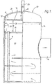
- a compressed air dryer 10 is shown in a partially sectioned side view, which has the features of the invention.
- the compressed air dryer comprises a cylindrical housing 12 with a plate-like holding device or tube plate 16 holding heat exchanger tubes 14.
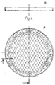
- the individual ends of the individual tubes 14 are pressure-tight with the outer surface in the tube plate, which is shown again in FIG. 4 from above and from the side used, for example soldered.
- the pressure plate 16 can carry a very large number of such tubes, in the embodiment shown in FIG. 4 there are, for example, 227 tubes, of which only those near the edge region are shown, while the tubes present in the remaining regions simply through the interface from two intersecting lines is indicated.
- the plate 16 divides the housing 12 of the compressed air heat exchanger 10 into a coolant supply space 18 and a compressed air space 20 and is held in a suitable manner, for example by means of a flanged edge 22 on the inner wall 24, which here can also form a shoulder 26 formed by enlarging the inner diameter, for example by gluing or welding.
- the coolant is supplied via a feed pipe 30 which is arranged in the dome 28 of the housing 10 and, as is usually the case here, is arranged in the center of the dome.
- the lower end of the compressed air dryer 10 can be seen in FIG.
- a plate-shaped holding device 116 sealingly enclosing the lower ends of the heat exchanger tubes 14 in a manner similar to the upper end and being fastened in an analogous manner to the inner surface of the cylindrical housing 12.
- the plate 116 also separates the compressed air space 20 from a coolant discharge space 118, from which the coolant can be drawn off via a discharge connection 32, in order to be fed back in a circuit on the feed pipe 30 after corresponding renewed removal of thermal energy.
- a sensor device can be used which measures the temperature or the pressure of the coolant collecting in the coolant discharge space 118, such a sensor being able to be inserted into the housing via an opening 34.
- Compressed air to be dried is introduced into the compressed air space 20 via the compressed air supply connection 36 and flows, meanderingly guided back and forth through mutually arranged deflection plates 38, in the counterflow direction to the coolant flow direction and is thereby passed through the surfaces of the heat exchanger tubes 14 through which coolant flows are cooled down to a temperature of close to 0 ° when they emerge from the compressed air discharge connector 40.
- Moisture contained in the compressed air condenses as a result of the lowering of the temperature and is deposited on the outer surfaces of the heat exchanger tubes 14 and on the deflection plates 38 and the inner walls of the housing 12 and runs down to the plate 116, where it is carried out via a pipe 42 by means of condensate drainage devices (not shown) can be deducted.
- a distributor plate 70 is used, which is arranged between the inlet tube 30 and the tube plate 16 and which has openings or such near its edge shown here, has notches 72 at the edge.
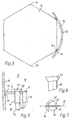
- These openings or incisions located near the edge or at the edge can be achieved in that the distributor plate as shown in FIG. 3 is given the peripheral shape of a polygon, here a hexagon, the distributor plate 70 then having its corners 74 on the wall of the cylindrical one Housing 12 can be fastened, for example by spot welding 76.
- This construction is particularly simple and inexpensive to manufacture because the base plate 70 can be produced by simply cutting it to size and the subsequent fastening in the housing can be accomplished, for example, by six spot welds.
- This type of distributor plate has proven particularly useful in the case of a tube plate with soldered tube ends distributed over the entire surface, as shown in FIG. 4, the tube ends not or only slightly according to FIG. 5 protrude beyond the tube plate into the volume of the feed chamber 18.
- the operation of the distributor plate 70 is particularly favorable if the ratio of the distance 78 (or, if the ends of the tubes 14 should protrude far into the feed chamber, the distance to the mouths of these tubes) and the distributor plate 70 and the inner diameter 80 of the cylindrical housing 12 between 1: 3 and 1:10. Ratios between 1: 4 and 1: 6 are particularly favorable. At the same time, the ratio of the distance 82 between the distributor plate 70 and the pipe mouth 84 of the fluid inflow 30 to the inside diameter 80 of the housing 12 should be between 1:10 and 1: 3, preferably between 1: 6 and 1: 4.
- the head 47 forms a kind of deflection wing and can thus control the flow of coolant near the surface of the tube plate 16: if the head or wing 47, as shown, has its wing longitudinal axis 51 radially inward, this will be done on the side fluid flowing inside opposes very little flow resistance. You twist against it displaced from this direction up to a maximum of 90 °, this results in a maximum flow resistance for the liquid flowing from the outside inwards. With the aid of the adjustment of these heads 47, the distribution can be fine-tuned under certain circumstances if this should be expedient.
- the displacement body 46 also serves to increase the flow resistance by restricting the inner lumen of the outer tube 44 of the heat exchanger tube 14 to a substantially uniformly extending annular space 48 and thereby concentrating the cooling liquid on the inner surface of the outer tube 44 and thereby improves the heat transfer resistance of the overall arrangement.
Landscapes
- Physics & Mathematics (AREA)
- Engineering & Computer Science (AREA)
- Thermal Sciences (AREA)
- Chemical & Material Sciences (AREA)
- Geometry (AREA)
- Mechanical Engineering (AREA)
- General Engineering & Computer Science (AREA)
- Analytical Chemistry (AREA)
- General Chemical & Material Sciences (AREA)
- Oil, Petroleum & Natural Gas (AREA)
- Chemical Kinetics & Catalysis (AREA)
- Heat-Exchange Devices With Radiators And Conduit Assemblies (AREA)
Priority Applications (1)
| Application Number | Priority Date | Filing Date | Title |
|---|---|---|---|
| EP87113947A EP0308529A1 (fr) | 1987-09-23 | 1987-09-23 | Echangeur de chaleur à faisceau tubulaire avec plaque de distribution |
Applications Claiming Priority (1)
| Application Number | Priority Date | Filing Date | Title |
|---|---|---|---|
| EP87113947A EP0308529A1 (fr) | 1987-09-23 | 1987-09-23 | Echangeur de chaleur à faisceau tubulaire avec plaque de distribution |
Publications (1)
| Publication Number | Publication Date |
|---|---|
| EP0308529A1 true EP0308529A1 (fr) | 1989-03-29 |
Family
ID=8197304
Family Applications (1)
| Application Number | Title | Priority Date | Filing Date |
|---|---|---|---|
| EP87113947A Withdrawn EP0308529A1 (fr) | 1987-09-23 | 1987-09-23 | Echangeur de chaleur à faisceau tubulaire avec plaque de distribution |
Country Status (1)
| Country | Link |
|---|---|
| EP (1) | EP0308529A1 (fr) |
Cited By (2)
| Publication number | Priority date | Publication date | Assignee | Title |
|---|---|---|---|---|
| EP1738661A1 (fr) * | 2005-06-29 | 2007-01-03 | deuka Deutsche Kraftfutterwerke GmbH & Co. | Procédé de fabrication de produits alimentaires intermédiaires et/ou de mélanges alimentaires pour animaux |
| CN119103917A (zh) * | 2024-11-07 | 2024-12-10 | 中国核动力研究设计院 | 一种基于ai的智能内插式换热器封头及运行状态监控方法 |
Citations (7)
| Publication number | Priority date | Publication date | Assignee | Title |
|---|---|---|---|---|
| US2178095A (en) * | 1938-01-07 | 1939-10-31 | H O Bowser Mfg Company | Means for equalizing the flow in heat exchange |
| US2915294A (en) * | 1958-03-19 | 1959-12-01 | Young Radiator Co | Heat exchanger and turbulator retainer therefor |
| GB908806A (en) * | 1959-08-20 | 1962-10-24 | Happel Gmbh | Improvements in or relating to surface condensers |
| US3630276A (en) * | 1970-02-10 | 1971-12-28 | Nasa | Shell-side liquid metal boiler |
| US3963466A (en) * | 1975-02-18 | 1976-06-15 | Hynes William M | Compressed gas drying apparatus |
| DE3136866A1 (de) * | 1981-09-17 | 1983-03-31 | Schwelmer Eisenwerk Müller & Co GmbH, 5830 Schwelm | "roehrenwaermetauscher mit stroemungsleiteinbauten" |
| DE3511037A1 (de) * | 1985-03-27 | 1986-10-09 | Voith Turbo Gmbh & Co Kg, 7180 Crailsheim | Waermetauscher |
-
1987
- 1987-09-23 EP EP87113947A patent/EP0308529A1/fr not_active Withdrawn
Patent Citations (7)
| Publication number | Priority date | Publication date | Assignee | Title |
|---|---|---|---|---|
| US2178095A (en) * | 1938-01-07 | 1939-10-31 | H O Bowser Mfg Company | Means for equalizing the flow in heat exchange |
| US2915294A (en) * | 1958-03-19 | 1959-12-01 | Young Radiator Co | Heat exchanger and turbulator retainer therefor |
| GB908806A (en) * | 1959-08-20 | 1962-10-24 | Happel Gmbh | Improvements in or relating to surface condensers |
| US3630276A (en) * | 1970-02-10 | 1971-12-28 | Nasa | Shell-side liquid metal boiler |
| US3963466A (en) * | 1975-02-18 | 1976-06-15 | Hynes William M | Compressed gas drying apparatus |
| DE3136866A1 (de) * | 1981-09-17 | 1983-03-31 | Schwelmer Eisenwerk Müller & Co GmbH, 5830 Schwelm | "roehrenwaermetauscher mit stroemungsleiteinbauten" |
| DE3511037A1 (de) * | 1985-03-27 | 1986-10-09 | Voith Turbo Gmbh & Co Kg, 7180 Crailsheim | Waermetauscher |
Cited By (2)
| Publication number | Priority date | Publication date | Assignee | Title |
|---|---|---|---|---|
| EP1738661A1 (fr) * | 2005-06-29 | 2007-01-03 | deuka Deutsche Kraftfutterwerke GmbH & Co. | Procédé de fabrication de produits alimentaires intermédiaires et/ou de mélanges alimentaires pour animaux |
| CN119103917A (zh) * | 2024-11-07 | 2024-12-10 | 中国核动力研究设计院 | 一种基于ai的智能内插式换热器封头及运行状态监控方法 |
Similar Documents
| Publication | Publication Date | Title |
|---|---|---|
| EP0828980B1 (fr) | Echangeur de chaleur | |
| DE69809652T2 (de) | Verteiler für Röhrenwärmetauscher einer Zweiphasenkältemittel-Kühlanlage | |
| DE60310876T2 (de) | Getauchter verdampfer mit integriertem wärmeaustauscher | |
| DE69529146T2 (de) | Destillationskolonne mit innerem wärmeaustausch | |
| DE3528426A1 (de) | Druckaufloeser - giessmassenerhitzer | |
| DE69500676T2 (de) | Wärmetauscher | |
| DE3440064C2 (fr) | ||
| DE1902200B1 (de) | Vorrichtung zum Mischen von Stoffen | |
| DE1986546U (de) | Waermetauscher. | |
| EP0308529A1 (fr) | Echangeur de chaleur à faisceau tubulaire avec plaque de distribution | |
| EP0386131B1 (fr) | Echangeur de chaleur a contre-courant | |
| EP0674148B1 (fr) | Radiateur pour chauffer | |
| EP0137119A2 (fr) | Générateur de vapeur | |
| DE10236665B4 (de) | Gas-Flüssigkeits-Wärmetauscher und damit ausgerüsteter Boiler | |
| DE69515443T2 (de) | Vorrichtung zur Zirkulation eines Fluids | |
| EP0387377A1 (fr) | Echangeur de chaleur à faisceau tubulaire | |
| DE1501369C3 (de) | Schachtförmiger Wärmetauscher | |
| EP0893667A2 (fr) | Echangeur de chaleur à plaques,sans caisson | |
| DE3036334C2 (de) | Wärmeübertrager | |
| EP1788339B1 (fr) | Echangeur de chaleur à plaques | |
| DE8903349U1 (de) | Rohrbündelwärmetauscher | |
| DE2047536C3 (de) | Einrichtung im Kochersystem eines mit inertem Gas arbeitenden Absorptionskälteapparats | |
| DE1501591C3 (de) | Kreuzstromwärmetauscher | |
| EP0133271B1 (fr) | Générateur pour une pompe à chaleur à sorption | |
| CH641893A5 (en) | Heat exchanger element, method for producing it, and a heat exchanger |
Legal Events
| Date | Code | Title | Description |
|---|---|---|---|
| PUAI | Public reference made under article 153(3) epc to a published international application that has entered the european phase |
Free format text: ORIGINAL CODE: 0009012 |
|
| AK | Designated contracting states |
Kind code of ref document: A1 Designated state(s): AT BE CH DE ES FR GB GR IT LI LU NL SE |
|
| STAA | Information on the status of an ep patent application or granted ep patent |
Free format text: STATUS: THE APPLICATION IS DEEMED TO BE WITHDRAWN |
|
| 18D | Application deemed to be withdrawn |
Effective date: 19890930 |
|
| RIN1 | Information on inventor provided before grant (corrected) |
Inventor name: BURK,JUERGEN |