EP0308840A2 - Eigensicheres Rückkopplungssystem mit Potentiometer - Google Patents
Eigensicheres Rückkopplungssystem mit Potentiometer Download PDFInfo
- Publication number
- EP0308840A2 EP0308840A2 EP88115292A EP88115292A EP0308840A2 EP 0308840 A2 EP0308840 A2 EP 0308840A2 EP 88115292 A EP88115292 A EP 88115292A EP 88115292 A EP88115292 A EP 88115292A EP 0308840 A2 EP0308840 A2 EP 0308840A2
- Authority
- EP
- European Patent Office
- Prior art keywords
- voltage
- wiper
- potentiometer
- motor
- microcomputer
- Prior art date
- Legal status (The legal status is an assumption and is not a legal conclusion. Google has not performed a legal analysis and makes no representation as to the accuracy of the status listed.)
- Withdrawn
Links
Images



Classifications
-
- F—MECHANICAL ENGINEERING; LIGHTING; HEATING; WEAPONS; BLASTING
- F23—COMBUSTION APPARATUS; COMBUSTION PROCESSES
- F23N—REGULATING OR CONTROLLING COMBUSTION
- F23N3/00—Regulating air supply or draught
-
- G—PHYSICS
- G05—CONTROLLING; REGULATING
- G05B—CONTROL OR REGULATING SYSTEMS IN GENERAL; FUNCTIONAL ELEMENTS OF SUCH SYSTEMS; MONITORING OR TESTING ARRANGEMENTS FOR SUCH SYSTEMS OR ELEMENTS
- G05B19/00—Program-control systems
- G05B19/02—Program-control systems electric
- G05B19/18—Numerical control [NC], i.e. automatically operating machines, in particular machine tools, e.g. in a manufacturing environment, so as to execute positioning, movement or co-ordinated operations by means of program data in numerical form
- G05B19/406—Numerical control [NC], i.e. automatically operating machines, in particular machine tools, e.g. in a manufacturing environment, so as to execute positioning, movement or co-ordinated operations by means of program data in numerical form characterised by monitoring or safety
- G05B19/4062—Monitoring servoloop, e.g. overload of servomotor, loss of feedback or reference
-
- G—PHYSICS
- G05—CONTROLLING; REGULATING
- G05B—CONTROL OR REGULATING SYSTEMS IN GENERAL; FUNCTIONAL ELEMENTS OF SUCH SYSTEMS; MONITORING OR TESTING ARRANGEMENTS FOR SUCH SYSTEMS OR ELEMENTS
- G05B19/00—Program-control systems
- G05B19/02—Program-control systems electric
- G05B19/18—Numerical control [NC], i.e. automatically operating machines, in particular machine tools, e.g. in a manufacturing environment, so as to execute positioning, movement or co-ordinated operations by means of program data in numerical form
- G05B19/19—Numerical control [NC], i.e. automatically operating machines, in particular machine tools, e.g. in a manufacturing environment, so as to execute positioning, movement or co-ordinated operations by means of program data in numerical form characterised by positioning or contouring control systems, e.g. to control position from one programmed point to another or to control movement along a programmed continuous path
- G05B19/33—Numerical control [NC], i.e. automatically operating machines, in particular machine tools, e.g. in a manufacturing environment, so as to execute positioning, movement or co-ordinated operations by means of program data in numerical form characterised by positioning or contouring control systems, e.g. to control position from one programmed point to another or to control movement along a programmed continuous path using an analogue measuring device
- G05B19/35—Numerical control [NC], i.e. automatically operating machines, in particular machine tools, e.g. in a manufacturing environment, so as to execute positioning, movement or co-ordinated operations by means of program data in numerical form characterised by positioning or contouring control systems, e.g. to control position from one programmed point to another or to control movement along a programmed continuous path using an analogue measuring device for point-to-point control
- G05B19/351—Numerical control [NC], i.e. automatically operating machines, in particular machine tools, e.g. in a manufacturing environment, so as to execute positioning, movement or co-ordinated operations by means of program data in numerical form characterised by positioning or contouring control systems, e.g. to control position from one programmed point to another or to control movement along a programmed continuous path using an analogue measuring device for point-to-point control the positional error is used to control continuously the servomotor according to its magnitude
-
- G—PHYSICS
- G05—CONTROLLING; REGULATING
- G05B—CONTROL OR REGULATING SYSTEMS IN GENERAL; FUNCTIONAL ELEMENTS OF SUCH SYSTEMS; MONITORING OR TESTING ARRANGEMENTS FOR SUCH SYSTEMS OR ELEMENTS
- G05B2219/00—Program-control systems
- G05B2219/30—Nc systems
- G05B2219/34—Director, elements to supervisory
- G05B2219/34215—Microprocessor
-
- G—PHYSICS
- G05—CONTROLLING; REGULATING
- G05B—CONTROL OR REGULATING SYSTEMS IN GENERAL; FUNCTIONAL ELEMENTS OF SUCH SYSTEMS; MONITORING OR TESTING ARRANGEMENTS FOR SUCH SYSTEMS OR ELEMENTS
- G05B2219/00—Program-control systems
- G05B2219/30—Nc systems
- G05B2219/34—Director, elements to supervisory
- G05B2219/34491—Count certain number of faults before delivering alarm or stop
-
- G—PHYSICS
- G05—CONTROLLING; REGULATING
- G05B—CONTROL OR REGULATING SYSTEMS IN GENERAL; FUNCTIONAL ELEMENTS OF SUCH SYSTEMS; MONITORING OR TESTING ARRANGEMENTS FOR SUCH SYSTEMS OR ELEMENTS
- G05B2219/00—Program-control systems
- G05B2219/30—Nc systems
- G05B2219/37—Measurements
- G05B2219/37462—Resistor, potentiometers
-
- G—PHYSICS
- G05—CONTROLLING; REGULATING
- G05B—CONTROL OR REGULATING SYSTEMS IN GENERAL; FUNCTIONAL ELEMENTS OF SUCH SYSTEMS; MONITORING OR TESTING ARRANGEMENTS FOR SUCH SYSTEMS OR ELEMENTS
- G05B2219/00—Program-control systems
- G05B2219/30—Nc systems
- G05B2219/37—Measurements
- G05B2219/37536—Rate of change, derivative
-
- G—PHYSICS
- G05—CONTROLLING; REGULATING
- G05B—CONTROL OR REGULATING SYSTEMS IN GENERAL; FUNCTIONAL ELEMENTS OF SUCH SYSTEMS; MONITORING OR TESTING ARRANGEMENTS FOR SUCH SYSTEMS OR ELEMENTS
- G05B2219/00—Program-control systems
- G05B2219/30—Nc systems
- G05B2219/42—Servomotor, servo controller kind till VSS
- G05B2219/42306—Excess in error, compare reference with feedback
-
- G—PHYSICS
- G05—CONTROLLING; REGULATING
- G05B—CONTROL OR REGULATING SYSTEMS IN GENERAL; FUNCTIONAL ELEMENTS OF SUCH SYSTEMS; MONITORING OR TESTING ARRANGEMENTS FOR SUCH SYSTEMS OR ELEMENTS
- G05B2219/00—Program-control systems
- G05B2219/30—Nc systems
- G05B2219/42—Servomotor, servo controller kind till VSS
- G05B2219/42329—Defective measurement, sensor failure
Definitions
- the potentiometer driven by the motor or its load can provide an inaccurate signal under many different types of fault conditions.
- the potentiometer can become open circuited, its wiper can become disengaged from the potentiometer body by dirt or wear, or the potentiometer can become so worn as to provide an inaccurate feedback signal.
- the accuracy of the feedback signal is critical. In these types of situations other means in addition to a potentiometer feedback system are utilized.
- the present invention therefor is directed to a position monitoring system, that uses a potentiometer, fail-safe. This is achieved by the features as characterized in the independent claims.
- the shortcomings of a potentiometer-based position monitoring system are overcome in the present invention by monitoring a number of parameters from the potentiometer means.
- the movement of the wiper on the potentiometer may be a rotational movement or a longitudinal movement.
- the motor may be an electrical or any other motor, such as pneumatic, and the wiper may be linked to the motor or to a load driven by said motor.
- Control systems incorporating position feedback potentiometers are widely used in the field of process control, so that the practical application of the invention is by no means limited to a damper in a burner control system.
- a microcomputer-based system supplies a regulated voltage to a potentiometer and measures its wiper voltage and its applied voltage. The measured voltages are fed through an analog-to-digital converter into the microcomputer that controls the motor or actuator position.
- the microcomputer checks a number of parameters of the voltage to and from the potentiometer means, and thereby is able to determine whether the position signal being received by the microcomputer is reliable. By checking the veracity of the position signal with the microcomputer, it is possible to substitute a very simple potentiometer position feedback system for a system which typically would utilize multiple switches for monitoring whether an output load reaches its required positions. Further details are described in the dependent claims.
- the present invention is particularly adapted for monitoring the position of a load such as a combustion air damper in a fuel burner system.
- Fuel burner systems typically require that switches be mechanically operated by the combustion air damper to verify certain damper positions.
- switches be mechanically operated by the combustion air damper to verify certain damper positions.
- it is possible to use a damper position feedback potentiometer and eliminate the switches.
- the monitoring of voltage to and from the potentiometer means checks many of its functions and determines whether a voltage is within expected limits, and whether a voltage is changing in an expected manner.
- the direction and rate of potentiometer wiper voltage change is compared with values either stored in microcomputer memory or determined by the position control program stored in computer memory.
- the microcomputer system includes a clock or timer function, the time required for a given load position change can be used as a further safety-related parameter.
- a flame safeguard sequencer for the control of a fuel burner upon the operation of controller means with said fuel burner having damper means, ignition means, fuel supply means, and flame sensor means, including: a flame safeguard sequencer connected to said damper means, said ignition means, said fuel supply means, and said flame sensor means to sequentially operate said means to properly purge, ignite and operate said fuel burner in a predetermined timed sequence upon operation of said controller means; said flame sensor means energized by said sequencer to monitor said burner for the presence or absence of flame upon said controller means operating to initiate the operation of said fuel burner; a fail-safe position monitoring system for said damper means with said damper means having motor means and motor position feedback potentiometer means; said flame safeguard sequencer further having voltage output means; said voltage output means providing an energizing voltage to said potentiometer means; said motor means including said feedback potentiometer means with said motor means constructed and arranged to operate a wiper of said feedback potentiometer means to provide a feedback voltage to said flame safeguard sequence
- a fail-safe electronic position monitoring system for motor means having motor position feedback potentiometer means including: control system means having input means and output means with said input means responsive to a control input command, and having output signal means connected to control said motor means; said output means further providing an energizing voltage to said potentiometer means; said motor means having an output member adapted to operate a load; said motor means including said feedback potentiometer means with said motor means constructed and arranged to operate a wiper of said feedback potentiometer means to provide a feedback voltage to said control system as an indication of a position of said output member; said control system input means receiving said feedback voltage; said control system including microcomputer means having memory means, and said microcomputer means with said memory means comparing said feedback voltage and said energinzing voltage levels stored in said memory means for proper operation of said sequencer; and safety system means including said microcomputer means for comparison of said voltages to an established voltage level profile stored in said memory means to check the veracity of the position monitoring system.
- FIG 1 there is schematically disclosed a fuel burner 10 which is operated under the control of a flame safeguard sequencer 11.
- the flame sequencer 11 typically would operate the fuel burner 10 in any conventional sequence.
- the fuel burner is disclosed as having an air inlet 13 with air flow schematically indicated at 14.
- the air flow 13 is regulated by a damper 15 that is driven by a damper drive motor 16.
- the damper 15 is shown in a semiclosed position which will be referred to as a low fire position.
- a second position disclosed at 17, with the damper open, will be referred to as a high fire position.
- the damper drive motor 16 is connected by conductors 25 to the flame safeguard sequencer 11 so that the motor 16 can be operated to drive the damper 15.
- a fail-safe potentiometer 18 is disclosed as having a wiper 19 with the wiper mechanically coupled at 21 to the motor 16. As the motor 16 operates, the wiper 19 co-operates with the potentiometer 18. A voltage is supplied by conductors 22 and 23 to the potentiometer 18 from the flame safeguard sequencer 11. The manner in which the voltage is supplied will be shown in more detail in connection with Figure 2.
- the wiper 19 provides a feedback voltage by a conductor 24 to a microcomputer control system 55 that functions within the flame safeguard sequencer 11.
- the fuel burner 10 further has a fan or air source 26 driven by a conventional motor 27 that is connected by conductors 28 to the sequencer 11.
- An air flow or sail switch 29 is proved to sense the actual flow of air and is connected by conductors 37 to the sequencer 11.
- the fan 26 provides the burner 10 with an air flow 14 from the inlet 13 to the stack 12 to provide combustion air and to provide a prepurge and postpurge operation of the burner, when required, and is proven by switch 29.
- a burner is schematically disclosed at 30 mounted to the bottom 31 of the burner chamber 10 is supplied with fuel by a pipe 32 from a valve 33 connected to a fuel line 34.
- the valve 33 is connected by electric conductors 35 to the sequencer 11, and also can be connected by a linkage 36 to the damper 15. This is done in order to adjust the flow of fuel through the valve 33 with the position of the damper 15, in addition to controlling the fuel flow through the valve 33 in an off-on manner by control signals via conductors 35.
- a pilot burner 40 is mounted at the main fuel burner 30 and is connected by a pipe 41 to a pilot fuel valve 42 that has electrical connection means or conductors 43 connected to the sequencer 11.
- the pilot fuel valve 42 is connected by a pipe 44 to the main fuel pipe 34, as would be used in a gas only installation.
- the particular type of fuel for the main burner 30 and the pilot burner 40 is not material to the present invention, and the presently disclosed arrangement is purely schematic in nature in order to provide an explanation of an operation of the present invention.
- the burner system 10 is completed by the provision of an ignition source 45 disclosed as a pair of spark electrodes that are connected to a spark generating means 46 that is connected by conductors 47 to the sequencer 11 to receive power and control. Also provided is a flame sensor 50 that is connected by conductors 51 to a flame sensor amplifier 52. The amplifier 52 can be designed to plug into the flame safeguard sequencer 11. The sequencer 11 is energized from a conventional line source at 53. The burner system 10 is activated upon the operation of a controller 59, e. g. a thermostat.
- a controller 59 e. g. a thermostat.
- a fail-safe electronic position monitoring system is shown in a more general form for control of motor means 16.
- the motor means 16 typically would have a motor and gear train 16′ to drive an output means coupled at 21′ to the load 15 and at 21 to drive the position feedback potentiometer wiper 19.
- the motor and gear train 16′ are energized over conductors 25 from the control system 55 in a conventional manner and the details of the energizing potential have not been shown.
- the control system 55 could be operating an electro-pneumatic type of motor 16 to drive a load 15.
- the present invention is not limited specifically to an electrical motor, but is directed generally to any type of motor means having an output 21′ adapted to drive a load 15.
- the only portion of the motor means 16 that is essentially electrical or electronic is the potentiometer means 18 and the wiper 19.
- a regulated voltage supply 60 is provided within the control system 55 along with a multi-input analog-to-digital converter shown at 61.
- the voltage regulator supplies a regulated potential at terminals 62 and 63 to in turn provide a regulated voltage on the conductors 22 and 23 to bias the potentiometer means 18. Under these circumstances, a voltage will be fed back on conductor 24 from the wiper 19, and that voltage has a direct relationship to the position of the wiper 19 with respect to the potentiometer means 18.
- the feedback voltage from the wiper 19 is provided by the conductor 24 to a terminal 64 which in turn is connected to the analog-to-digital converter 61.
- the analog-to-digital converter also monitors the regulated voltage at terminal 62.
- the analog-to-digital converter 61 provides a digital output at data bus 65 that is connected to a microcomputer 66.
- the microcomputer 66 contains a memory 67, and further would have a safety system 70, and a counter and timer means 71.
- the overall control system 55 receives a control input command 72 that could be a command such as that generated at the flame safeguard sequencer 11 of Figure 1.
- the load 15 would include the damper of the flame safeguard system shown in Figure 1.
- Figure 2 can be readily applied to the flame safeguard sequencer of Figure 1, or could stand by itself as a fail-safe electronic follow-up system for any type of motor means having a motor position follow-up potentiometer means 18.
- the control input command 72 instructs the microcomputer 66 of the need to change a position of the load 15.
- the microcomputer 66 provides an output on conductors 25 to the motor and gear train 16′ of the motor means 16.
- the motor means 16 operates through the means 21 and gear train 21′ to drive the load 15.
- the load 15 again would be a damper in the burner system 10 of Figure 1.
- the wiper 19 moves with respect to the potentiometer means 18 and an analog output voltage is fed back via line 24 through terminal 64 to the analog-to-digital converter 61 which converts it to digital form and sends it to the microcomputer 66 via data bus 65.
- the microcomputer 66 compares the feedback voltage against the value that should be attained for the commanded motor position. While the motor is in motion, the microcomputer 66 evaluates the rate of wiper voltage change and its direction. This insures that the wiper 19 is moving at a preordained rate and a preordained direction (monotonocity test).
- the fail-safe electronic position monitoring system disclosed monitors a number of other potential faults. These will be brought out in detail in chart form in Figure 3. Very briefly, however, in the event that the supply line 22 opens, the wiper line 24 opens, or the common line 23 opens, the voltage fed back to the microcomputer 66 changes radically and can be immediately compared with the computed voltage requirement to substantially instantaneously detect a fault and cause an appropriate response. Many other functions are also monitored such as short circuits between the various conductors, a cracked or defective potentiometer means 18, a faulty analog-to-digital converter 61, a noisy joint in the system, and the quality or state of wear of the potentiometer by use of the monotonocity test along with the wiper position rate of change test. As previously indicated, these features are defined in the form of a chart in Figure 3, and by way of a flow chart of Figure 4 (A, B and C) which clearly defines the present invention.
- FIG 3 a chart of five tests are compared with 13 different types of faults. It is believed that the chart is substantially self-explanatory, but in order to provide guidance the first fault will be specifically reviewed. If line 22 open circuits, the fault is primarily detected by a low wiper voltage being detected. This is indicated by the letter P. Two secondary tests may also be failed; the monotonocity test would be failed if the direction of voltage change is improper for the commanded direction of motor position change. The response time monitoring test would be failed because the rate of wiper voltage change would not be within acceptable limits. In the case of the burner control system disclosed in Figure 1, the output of the flame safeguard sequencer 11 could respond to shut down the fuel burner 10 in a safe manner.
- Each of the faults in Figure 3 is defined as having a primary or secondary test, and each is believed self-evident by comparing the fault and the indicated test.
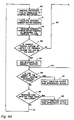
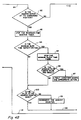
- FIG 4 (A, B and C) a flow chart defining the present invention in detail is provided.
- the flow chart deals with the concept disclosed in Figure 1 where a fuel burner 10 is operated in conjunction with the damper 15, and the damper 15 is monitored by potentiometer means 18.
- the microcomputer control system 55 is presented as specifically including a demerit counter and timer as indicated at 71 in the concept of Figure 2.
- the system is defined at 80 as performing processing that is unrelated to the damper monitoring.
- the system progresses to 81 where a calculation of the required damper motor position is made.
- a measurement is taken of the current damper motor position by measuring the feedback voltage from the potentiometer means 18.
- the system then progresses to a decision block 83 where a determination is made as to whether the feedback voltage is outside of acceptable limits. This test detects catastrophic failures such as opens or shorts. This is accomplished by the feedback voltage being measured as above or below fixed limits. If the decision at block 83 indicates that the feedback voltage is outside of its limits, the system at 85 adds 30 counts to a demerit counter 71 of Figure 2. A large demerit count rate reduces fault reaction time. The system then progresses to the decision block 86 to determine if the count in the demerit counter is too large. If it is too large, a fault condition is determined to exist and appropriate action is then taken at block 87 (such as a system shutdown and alarm).
- the decision making process then progresses to 88 where the response time monitor timer is tested to determine if the time it takes the motor to reach its desired position is too long; this detects an inoperative motor or position feedback system. If the response time monitor's value is too large, a fault condition is indicated at 90 and appropriate action is again taken. If the response time monitor's value is within acceptable limits, exit is made via path 91 and the sequence is repeated. When the test of block 83 is encountered, and if the feedback voltage is within limits, exit is via line 84 to block 92.
- Some burner control systems utilize the time that it takes the damper to open and close as a purge period. If the position feedback system is faulty, the purge period would be shortened. For cases like this, the sequencer sets a flag that is tested at block 94. The slew timer's value is compared against a minimum value at block 96. The appropriate action could be to hold the flame safeguard sequencer (11, Figure 1) until the minimum slew time is enforced, or to shut the system down and alarm).
- the output of the decision block 94 then flows to decision block 100 to determine whether the demerit counter is at zero. If it is not, the counter is decremented at 101. Thus, the demerit counter gradually returns to zero (but is prevented from becoming negative by decision block 100) during successive passes through these logic blocks, whenever normal operation is prevalent.
- the change in damper position per unit time is tested at 104 to determine whether the movement was larger or smaller than normal. If it was abnormal, the demerit counter has counts added at 105. (This monotonocity or slew rate test detects abnormal rates of change in damper feedback voltage). If it was not, the process continues to a decision block 106 to determine whether the demerit counter is at zero. If it is not, the counter is decremented at 107. The system next moves on to 108 where the information is saved for use in the next time through the loop.
- the system then proceeds to 110 where an inquiry is made as to whether or not a new damper motor position command is needed. If it is, the system proceeds to 111, the damper motor is caused to move by issuing a new command and the response-time timer means is activated. The minimum slew time flag is tested at 112. If it is set, the slew timer is reset and the timer is restarted. If at 112 the slew-time flag was not set, the system proceeds through another loop via 114.
Landscapes
- Engineering & Computer Science (AREA)
- Human Computer Interaction (AREA)
- Manufacturing & Machinery (AREA)
- Physics & Mathematics (AREA)
- General Physics & Mathematics (AREA)
- Automation & Control Theory (AREA)
- Chemical & Material Sciences (AREA)
- Combustion & Propulsion (AREA)
- Mechanical Engineering (AREA)
- General Engineering & Computer Science (AREA)
- Regulation And Control Of Combustion (AREA)
- Safety Devices In Control Systems (AREA)
Applications Claiming Priority (2)
| Application Number | Priority Date | Filing Date | Title |
|---|---|---|---|
| US99369 | 1987-09-21 | ||
| US07/099,369 US4866363A (en) | 1987-09-21 | 1987-09-21 | Fail-safe potentiometer feedback system |
Publications (2)
| Publication Number | Publication Date |
|---|---|
| EP0308840A2 true EP0308840A2 (de) | 1989-03-29 |
| EP0308840A3 EP0308840A3 (de) | 1990-01-10 |
Family
ID=22274670
Family Applications (1)
| Application Number | Title | Priority Date | Filing Date |
|---|---|---|---|
| EP88115292A Withdrawn EP0308840A3 (de) | 1987-09-21 | 1988-09-17 | Eigensicheres Rückkopplungssystem mit Potentiometer |
Country Status (6)
| Country | Link |
|---|---|
| US (1) | US4866363A (de) |
| EP (1) | EP0308840A3 (de) |
| JP (1) | JPH0198822A (de) |
| KR (1) | KR890005461A (de) |
| AU (1) | AU597559B2 (de) |
| CA (1) | CA1329645C (de) |
Cited By (5)
| Publication number | Priority date | Publication date | Assignee | Title |
|---|---|---|---|---|
| WO1991000957A1 (de) * | 1989-07-07 | 1991-01-24 | Robert Bosch Gmbh | System zur steuerung einer brennkraftmaschine |
| EP0433083A1 (de) * | 1989-12-14 | 1991-06-19 | Zymark Corporation | Vorrichtung zur Bestimmung der Winkelposition |
| WO1995008141A1 (de) * | 1993-09-13 | 1995-03-23 | Grundig Ag | Verfahren zur abstechkontrolle bei stangendrehautomaten |
| EP1022570A3 (de) * | 1999-01-22 | 2003-01-29 | Honeywell Inc. | Ausfallsicheres Überwachungssystem für ein Potentiometer |
| EP2015153A1 (de) * | 2007-07-11 | 2009-01-14 | Electrolux Home Products Corporation N.V. | System und Verfahren zur Verarbeitung eines Signals eines elektrischen Gerätes |
Families Citing this family (8)
| Publication number | Priority date | Publication date | Assignee | Title |
|---|---|---|---|---|
| US6647346B1 (en) | 2000-10-06 | 2003-11-11 | Emerson Electric Co. | Compressor control system and method therefor |
| US7252502B2 (en) * | 2004-01-27 | 2007-08-07 | Honeywell International Inc. | Method and system for combined standing pilot safety and temperature setting |
| TW200636192A (en) * | 2005-03-22 | 2006-10-16 | Miura Kogyo Kk | Damper position adjusting device and combustion apparatus having such damper adjusting device |
| US20070075824A1 (en) * | 2005-10-03 | 2007-04-05 | Honeywell International Inc. | Advanced thick film potentiometers |
| US7550981B2 (en) * | 2006-08-10 | 2009-06-23 | Honeywell International Inc. | Circuit and method for determining potentiometer wiper resistance |
| JP6879849B2 (ja) * | 2017-07-14 | 2021-06-02 | アズビル株式会社 | 燃焼システムおよび不調判定装置 |
| JP6850232B2 (ja) * | 2017-09-27 | 2021-03-31 | アズビル株式会社 | 燃焼システム |
| CN109167298B (zh) * | 2018-10-16 | 2020-09-29 | 国电南瑞科技股份有限公司 | 一种用于跨越架空地线耐张塔悬挂式过桥系统 |
Family Cites Families (11)
| Publication number | Priority date | Publication date | Assignee | Title |
|---|---|---|---|---|
| US4031442A (en) * | 1973-12-11 | 1977-06-21 | Kubik Hydradrives, Inc. | Electronic position and velocity control system |
| JPS5627132B2 (de) * | 1974-11-27 | 1981-06-23 | ||
| DE2837842A1 (de) * | 1978-08-30 | 1980-03-13 | Anschuetz & Co Gmbh | Anordnung zum ueberwachen einer rudersteueranlage |
| US4476415A (en) * | 1982-08-20 | 1984-10-09 | Johnson Service Company | Feedback transducer |
| US4481451A (en) * | 1982-08-20 | 1984-11-06 | Johnson Service Company | Electronically controlled positioner for pneumatic actuators |
| JPS5960068A (ja) * | 1982-09-30 | 1984-04-05 | Fuji Heavy Ind Ltd | 内燃機関の電子制御装置 |
| US4518345A (en) * | 1983-02-28 | 1985-05-21 | Emerson Electric Co. | Direct ignition gas burner control system |
| NO168215C (no) * | 1983-04-12 | 1992-01-22 | Niigata Engineering Co Ltd | System for styring av en dreiende mekanisme i en z-type fremdriftsanordning |
| US4484122A (en) * | 1983-05-16 | 1984-11-20 | James L. Day Co., Inc. | Variable potentiometer motor controller |
| JPS6082936U (ja) * | 1983-11-08 | 1985-06-08 | アルプス電気株式会社 | モータのロック防止をするモータ停止位置制御装置 |
| US4716519A (en) * | 1986-01-22 | 1987-12-29 | Nordson Corporation | Method of checking channel connections and detecting heater circuit and temperature sensor malfunctions in multi-channel closed loop hot melt heating systems |
-
1987
- 1987-09-21 US US07/099,369 patent/US4866363A/en not_active Expired - Fee Related
-
1988
- 1988-07-28 AU AU20171/88A patent/AU597559B2/en not_active Ceased
- 1988-08-10 CA CA000574277A patent/CA1329645C/en not_active Expired - Fee Related
- 1988-08-22 KR KR1019880010645A patent/KR890005461A/ko not_active Withdrawn
- 1988-09-16 JP JP63232108A patent/JPH0198822A/ja active Pending
- 1988-09-17 EP EP88115292A patent/EP0308840A3/de not_active Withdrawn
Cited By (10)
| Publication number | Priority date | Publication date | Assignee | Title |
|---|---|---|---|---|
| WO1991000957A1 (de) * | 1989-07-07 | 1991-01-24 | Robert Bosch Gmbh | System zur steuerung einer brennkraftmaschine |
| EP0433083A1 (de) * | 1989-12-14 | 1991-06-19 | Zymark Corporation | Vorrichtung zur Bestimmung der Winkelposition |
| WO1995008141A1 (de) * | 1993-09-13 | 1995-03-23 | Grundig Ag | Verfahren zur abstechkontrolle bei stangendrehautomaten |
| US5975746A (en) * | 1993-09-13 | 1999-11-02 | Dr. Johannes Heidenhain Gmbh | Process for monitoring bar cutoff on automatic bar lathes |
| EP1022570A3 (de) * | 1999-01-22 | 2003-01-29 | Honeywell Inc. | Ausfallsicheres Überwachungssystem für ein Potentiometer |
| EP2015153A1 (de) * | 2007-07-11 | 2009-01-14 | Electrolux Home Products Corporation N.V. | System und Verfahren zur Verarbeitung eines Signals eines elektrischen Gerätes |
| WO2009007041A1 (en) * | 2007-07-11 | 2009-01-15 | Electrolux Home Products Corporation N. V. | A system and a method for processing a signal from an electric device |
| AU2008274592B2 (en) * | 2007-07-11 | 2011-04-21 | Electrolux Home Products Corporation N. V. | A system and a method for processing a signal from an electric device |
| US8243037B2 (en) | 2007-07-11 | 2012-08-14 | Electrolux Home Products Corporation, N.V. | System and a method for processing a signal from an electric device |
| CN101681156B (zh) * | 2007-07-11 | 2012-09-19 | 伊莱克斯家用产品股份有限公司 | 处理电气装置的信号的系统和方法 |
Also Published As
| Publication number | Publication date |
|---|---|
| JPH0198822A (ja) | 1989-04-17 |
| AU597559B2 (en) | 1990-05-31 |
| KR890005461A (ko) | 1989-05-15 |
| US4866363A (en) | 1989-09-12 |
| AU2017188A (en) | 1989-03-23 |
| CA1329645C (en) | 1994-05-17 |
| EP0308840A3 (de) | 1990-01-10 |
Similar Documents
| Publication | Publication Date | Title |
|---|---|---|
| US4866363A (en) | Fail-safe potentiometer feedback system | |
| CA1139870A (en) | Dynamically checked safety laod switching circuit | |
| EP0308831B1 (de) | Flammendetektorsignal-Verarbeitungssystem | |
| CA1150796A (en) | Condition control system with safety feedback means | |
| US5513062A (en) | Power supply for a redundant computer system in a control system | |
| EP3059855B1 (de) | Elektrische steuereinrichtung | |
| US5446451A (en) | On board hot bearing detector system with fault detection | |
| US8485137B2 (en) | Combustion control device | |
| JPH0713482B2 (ja) | 燃料制御装置 | |
| JP6862920B2 (ja) | 給湯システム | |
| US4817045A (en) | Monitored control arrangement | |
| US5538416A (en) | Gas burner controller with main valve delay after pilot flame lightoff | |
| US4510549A (en) | Power supply voltage monitor and control system | |
| US4644238A (en) | Airflow control apparatus | |
| EP0861459B1 (de) | Überprüfung eines digitalen kontrollsystems | |
| US6507468B1 (en) | Controller for heat engineering installations | |
| US4992040A (en) | Airflow switch checking circuit | |
| JP2647567B2 (ja) | 調節弁の制御機構 | |
| EP2182604A1 (de) | Vorrichtung zur Überwachung der elektrischen Stromversorgung | |
| US4963088A (en) | Safety-related parameter inputs for microprocessor ignition controller | |
| EP0636954A1 (de) | Elektronisches Steuerpult für Boiler | |
| KR940005120B1 (ko) | 연소제어장치 | |
| EP0347179A2 (de) | Antiprell-Logik für kritische Lasten | |
| JP3120009B2 (ja) | 燃焼制御装置 | |
| JPH07230319A (ja) | サーボコントローラ系における配線異状の検出方法 |
Legal Events
| Date | Code | Title | Description |
|---|---|---|---|
| PUAI | Public reference made under article 153(3) epc to a published international application that has entered the european phase |
Free format text: ORIGINAL CODE: 0009012 |
|
| AK | Designated contracting states |
Kind code of ref document: A2 Designated state(s): AT BE CH DE ES FR GB GR IT LI LU NL SE |
|
| PUAL | Search report despatched |
Free format text: ORIGINAL CODE: 0009013 |
|
| AK | Designated contracting states |
Kind code of ref document: A3 Designated state(s): AT BE CH DE ES FR GB GR IT LI LU NL SE |
|
| STAA | Information on the status of an ep patent application or granted ep patent |
Free format text: STATUS: THE APPLICATION IS DEEMED TO BE WITHDRAWN |
|
| 18D | Application deemed to be withdrawn |
Effective date: 19900711 |