EP0308881A2 - Montre commandée par radio - Google Patents
Montre commandée par radio Download PDFInfo
- Publication number
- EP0308881A2 EP0308881A2 EP88115451A EP88115451A EP0308881A2 EP 0308881 A2 EP0308881 A2 EP 0308881A2 EP 88115451 A EP88115451 A EP 88115451A EP 88115451 A EP88115451 A EP 88115451A EP 0308881 A2 EP0308881 A2 EP 0308881A2
- Authority
- EP
- European Patent Office
- Prior art keywords
- display
- radio
- time
- alarm
- information
- Prior art date
- Legal status (The legal status is an assumption and is not a legal conclusion. Google has not performed a legal analysis and makes no representation as to the accuracy of the status listed.)
- Granted
Links
- 230000011664 signaling Effects 0.000 claims description 6
- 230000000737 periodic effect Effects 0.000 claims description 3
- 230000001960 triggered effect Effects 0.000 claims description 3
- 230000004913 activation Effects 0.000 claims 1
- 230000005540 biological transmission Effects 0.000 abstract 1
- 238000011084 recovery Methods 0.000 abstract 1
- 238000010586 diagram Methods 0.000 description 2
- 230000033764 rhythmic process Effects 0.000 description 2
- 238000012790 confirmation Methods 0.000 description 1
- 238000011161 development Methods 0.000 description 1
- 230000018109 developmental process Effects 0.000 description 1
- 230000000694 effects Effects 0.000 description 1
- 238000011156 evaluation Methods 0.000 description 1
- 238000009434 installation Methods 0.000 description 1
Images
Classifications
-
- G—PHYSICS
- G04—HOROLOGY
- G04G—ELECTRONIC TIME-PIECES
- G04G9/00—Visual time or date indication means
- G04G9/0005—Transmission of control signals
- G04G9/0011—Transmission of control signals using coded signals
-
- G—PHYSICS
- G04—HOROLOGY
- G04R—RADIO-CONTROLLED TIME-PIECES
- G04R20/00—Setting the time according to the time information carried or implied by the radio signal
-
- G—PHYSICS
- G04—HOROLOGY
- G04R—RADIO-CONTROLLED TIME-PIECES
- G04R20/00—Setting the time according to the time information carried or implied by the radio signal
- G04R20/08—Setting the time according to the time information carried or implied by the radio signal the radio signal being broadcast from a long-wave call sign, e.g. DCF77, JJY40, JJY60, MSF60 or WWVB
Definitions
- the invention relates to a radio clock according to the preamble of claim 1.
- Such a clock is from DE-PS 34 39 638 with presentation of the reception conditions by the drive rhythm of a pointer or from DE-OS 30 15 312 with presentation of the reception conditions as a digital quality figure with regard to the conformity of the pulses received by radio with a standard -Impulse shape known.
- the object of the invention is to provide an autonomous radio-controlled clock of the generic type with an even greater acceptance on the market by equipping it with corresponding additional benefits.
- This object is essentially achieved in that the generic radio clock is equipped according to the characterizing part of claim 1.
- This solution satisfies a subliminal but at least existing consumer wish to receive a confirmation of the accuracy of the time display of his autonomous radio clock: With the increase in the information displayed about the reception conditions, the most recent point in time of a check of the clock time display based on the legal, via radio widespread time increasingly further back; and it would be expedient to change the spatial orientation or the location of the radio clock in order to achieve better radio reception conditions.
- the fact of a current radio reception (evaluation of the time information received via radio) can be additionally displayed in a manner known per se, in particular in the cycle of the coding of the radio time information.
- the display about the reception conditions always maintains an optimal value, the consumer has the certainty that the periodic check of the time display of his watch could be carried out correctly on the basis of the legal time transmitted by radio, so that the time display is most likely correct. If, for example, at the preprogrammed point in time of a display check, the display of the reception conditions is incremented by one unit, and a reset to the start count state upon receipt of all evaluable time information occurs, the lowest value is continuously displayed and from this the information that for each intended The time of the check has actually been checked (and, if necessary, corrected) of the time display.
- the clock is equipped as an appointment clock (alarm clock), as is known as such from DE-OS 35 10 636.
- the display of the reception conditions is then expediently included in the display of the current time and the predetermined wake-up time, this display being able to be implemented as a pointer display, but preferably as a digital display.
- the additional display between the alarm time and the date (in any case, the day and the month).
- the manual display change is associated with one switching of the hour display and one switching of the minute display Key switch useful;
- these pushbuttons only serve to change the displayed alarm time, that is to say they have no influence on the displayed current time or on the displayed current date (because these displays are now checked and, if necessary, corrected by means of the time information received via radio).
- it also makes sense - as far as independent protection is concerned - to use these two switches assigned to manual display correction, depending on the position of an operating mode switch, for interrupting or ending an alarm signal or for switching the additional display (alarm time - date ).
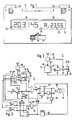
- the autonomous radio clock 11 consists of a radio receiver 12 and a control circuit 13 for checking and, if necessary, correcting the current time display in accordance with the current time information 10 transmitted periodically by a time normal transmitter and for subsequent subsequent internal operation until the next time information is received, as described in more detail in DE-PS 34 39 638.
- no analog pointer display is provided for the presentation of the time information, but a digital display with a display 14 made of grouped digits 15. At least one display element 16, in the example shown consisting of two digits 15 in addition to the other digital display on the display 14, is used to present information about current reception conditions.
- a counter 17 is acted upon by counting pulses from a clock generator 18 (which can be the time-keeping circuit for autonomous clock operation designed in connection with the control circuit 13) and information proportional to the counting result is presented via the display element 16.
- a clock generator 18 which can be the time-keeping circuit for autonomous clock operation designed in connection with the control circuit 13
- information proportional to the counting result is presented via the display element 16.
- the reset input R of the counter 17 is driven from the control circuit 13 to reset to the counting start state.
- the display element 16 presenting the reception conditions shows the higher the information value, the longer the last check of the time display 19 was made, the more uncertain the match between the current time display and the actual, current time has become.
- the counting start position of the counter 17 is at the value ZERO, an hourly counting pulse is output to the counter 17 and an hourly check of the current time display 19 with the time information 10 received by radio takes place, then the two-digit digital display element 16 always becomes kept at "00".
- this display increases every hour, then this means that the reception conditions at the installation site of the radio clock 11 are so bad that it was no longer possible to receive decodable, valid time information 10 over the number of hours displayed, and therefore the current time display 19 accordingly uncertain (since it has not been confirmed for a long time); which is why the radio clock 11 is moved as far as possible to another spatial position or environment in which the built-in antenna 20 again enables undisturbed radio reception as time information 10 that can be evaluated.
- This is done, for example, by means of a modulator circuit 21, which is controlled from the receiver 12 every second of the time information coding and thereby causes at least one of the digits 15 of the display element 16 to flash for a second.
- the display 14 also has an additional display 22 in addition to the time display 19, the display element 16 assigned to the radio reception conditions is expediently subordinate in size and other conspicuity in the middle between the two displays 19-22 and thus in the middle of the display 14. arranged as considered in Fig. 1.
- the additional display 22 can represent date information, as is also transmitted by radio and can be derived from the passage of time in the case of autonomous clock operation, shown, for example, via two pairs of digit-digits 15, each with a point 23 behind it.
- the additional display 22 can also be an alarm time display, consisting of the two digit-pair digits 15 with only one decimal point 23 arranged in between and preceding letter digits 15 "AL" (see FIG. 1). If the radio clock 11 is thus equipped as an appointment or alarm clock, the AL display 22 thus indicates the manually specified point in time at which an alarm signal 24 will be triggered.
- an operating mode switch S3 is set to the SET position, whereupon the button pair S1 or S2 gradually changes the digit or pair indicating the hours or the minutes, for example, in the rhythm of the manual switch actuation.
- any of the pushbuttons S1 and S2 causes the additional display 22 to switch between the alarm time specification (FIG. 1) and the date; wherein the display 22 just given can remain until the next key switch actuation, or, in terms of circuitry, a tilting back into a preferred display 22 can be provided.
- a coincidence stage 25 is activated which, if the predetermined alarm time matches the time actually reached, uses a coincidence signal 26 to provide a bistable stage 27 for controlling an alarm transmitter 28 (for example a piezoelectric converter) for emitting the Alarm signals 24 sets.
- an alarm transmitter 28 for example a piezoelectric converter
- the flip-flop 27 is reset via an exclusive-OR gate 29 and on the other hand a monostable flip-flop 30 is started in order to switch the bistable level 27 after a certain (circuit-specific) pause time to set the alarm again (SNOOZE wake-up function). If, on the other hand, both pushbuttons S1 and S2 are actuated simultaneously (overlapping in time), the exclusive OR gate 29 does not respond, but an AND gate 31 connected downstream of the switches S1, S2, via which the signaling stage 27 is reset.
- a flip-flop 32 triggers at least one signal that is very short in time (possibly peculiar in frequency or modulation), which serves as an acoustic acknowledgment for the overlapping actuation of the two pushbuttons S1-S2.
- This "AL STOP" actuation also means that an alarm signal 24 is only emitted again when (after 24 hours) a time coincidence between the current default display 22 and the current time display 19 is reached again.
- a time circuit 33 started in the set position of the alarm signaling stage 27 is used for the automatic termination of the delivery of the alarm signal 24 after a certain period of time, if there was no manual interruption or termination via the pushbuttons S1, S2; in order to avoid an ongoing disturbance of rest or an unnecessary load on the energy source (for example a battery) for the operation of the radio clock 11.
- the energy source for example a battery
- the bistable alarm stage 27 is expediently fixed in the reset position, so that an alarm cannot be triggered via the coincidence stage 25 for this reason alone.
- the gate circuit shown in FIG. 3 also ensures that only one (and currently only one) of the pushbuttons S1, S2 for modifying the alarm time specification to the coincidence stage 25 is actuated only in the SET position of the operating mode switch S3 leads; while in the other two positions (ON or OFF) a signal 34 is generated which enables the information to be switched over to the additional display 22 (date - alarm time) when any of the pushbuttons S1, S2 is actuated; However, in the interest of clarity in FIG. 3, this is not implemented in terms of circuitry.
- the gate circuit shown and the effects of the monostable and bistable flip-flops are advantageously not realized by a discrete circuit structure, but are perceived by additional functions of a central processor, which is in any case in the control circuit 13 for the periodic switching on of the receiver 12, for the decoding of the absolute time information 10 received by radio and, if necessary, for the correction of the time and date displays 19, 22.
Landscapes
- Physics & Mathematics (AREA)
- General Physics & Mathematics (AREA)
- Electric Clocks (AREA)
- Electromechanical Clocks (AREA)
Applications Claiming Priority (2)
| Application Number | Priority Date | Filing Date | Title |
|---|---|---|---|
| DE19873731956 DE3731956A1 (de) | 1987-09-23 | 1987-09-23 | Autonome funkuhr |
| DE3731956 | 1987-09-23 |
Publications (3)
| Publication Number | Publication Date |
|---|---|
| EP0308881A2 true EP0308881A2 (fr) | 1989-03-29 |
| EP0308881A3 EP0308881A3 (fr) | 1991-03-13 |
| EP0308881B1 EP0308881B1 (fr) | 1993-12-01 |
Family
ID=6336636
Family Applications (1)
| Application Number | Title | Priority Date | Filing Date |
|---|---|---|---|
| EP88115451A Expired - Lifetime EP0308881B1 (fr) | 1987-09-23 | 1988-09-21 | Montre commandée par radio |
Country Status (3)
| Country | Link |
|---|---|
| US (1) | US5083123A (fr) |
| EP (1) | EP0308881B1 (fr) |
| DE (3) | DE3731956A1 (fr) |
Cited By (6)
| Publication number | Priority date | Publication date | Assignee | Title |
|---|---|---|---|---|
| EP0455183A3 (en) * | 1990-05-04 | 1992-01-15 | Junghans Uhren Gmbh | Autonomous radio clock |
| EP0439725A3 (en) * | 1990-01-31 | 1992-01-15 | Junghans Uhren Gmbh | Autonomous radio clock |
| EP0504690A1 (fr) * | 1991-03-16 | 1992-09-23 | DIEHL GMBH & CO. | Simulateur d'effet d'arme assisté par laser |
| US5408445A (en) * | 1991-08-23 | 1995-04-18 | Junghans Uhren Gmbh | Radio timepiece |
| EP0656572A1 (fr) * | 1993-12-01 | 1995-06-07 | Seiko Instruments Inc. | Montre électronique corrigée par radio |
| EP0657794A3 (fr) * | 1993-12-07 | 1995-12-13 | Casio Computer Co Ltd | Dispositif de réception de données de temps. |
Families Citing this family (13)
| Publication number | Priority date | Publication date | Assignee | Title |
|---|---|---|---|---|
| DE9010813U1 (de) * | 1990-07-20 | 1991-11-14 | Junghans Uhren GmbH, 7230 Schramberg | Autonome Funkuhr |
| DE4230531C1 (de) * | 1992-09-12 | 1993-11-18 | Braun Ag | Funkuhr |
| DE4233126A1 (de) * | 1992-10-02 | 1994-04-07 | Telefunken Microelectron | Verfahren für den Betrieb einer Funkuhr und Funkuhr für den Einsatz in einem störfeldbehafteten Umfeld |
| DE4416869A1 (de) * | 1994-05-13 | 1995-11-16 | Opel Adam Ag | Steuereinrichtung für eine durch Funksignale zu synchronisierende Uhr |
| JPH10341466A (ja) * | 1997-06-10 | 1998-12-22 | Nec Shizuoka Ltd | 無線選択呼出受信機 |
| US7230884B2 (en) * | 2003-01-03 | 2007-06-12 | The Sapling Company, Inc. | Clock diagnostics |
| US6958953B2 (en) * | 2003-05-13 | 2005-10-25 | International Business Machines Corporation | Real time clock circuit having an internal clock generator |
| US7068569B2 (en) * | 2003-08-08 | 2006-06-27 | John Dutkiewicz | Apparatus and method for displaying time and randomly-selected text information |
| JP3876887B2 (ja) * | 2004-02-04 | 2007-02-07 | カシオ計算機株式会社 | 電波受信装置、電波受信回路、電波時計及び中継器 |
| US20050250551A1 (en) * | 2004-05-10 | 2005-11-10 | Nokia Corporation | Notification about an event |
| US20050259722A1 (en) * | 2004-05-21 | 2005-11-24 | Reginald Vanlonden | Wireless clock system |
| KR100782513B1 (ko) * | 2006-03-14 | 2007-12-05 | 삼성전자주식회사 | 디지털 방송 데이터의 수신이 가능한 이동통신 단말기 및그의 알람 수행 방법 |
| JP2008170230A (ja) * | 2007-01-10 | 2008-07-24 | Seiko Epson Corp | 時刻修正装置、時刻修正装置付き計時装置及び時刻修正方法 |
Family Cites Families (12)
| Publication number | Priority date | Publication date | Assignee | Title |
|---|---|---|---|---|
| US3795099A (en) * | 1971-02-18 | 1974-03-05 | Y Tsuruishi | Electronic timepiece having a chronograph mechanism |
| DE2425254C3 (de) * | 1973-05-28 | 1980-11-20 | Citizen Watch Co., Ltd., Tokio | Tragbare elektronische Uhr |
| JPS5357876A (en) * | 1976-11-05 | 1978-05-25 | Citizen Watch Co Ltd | Watch with battery life warning display |
| US4255803A (en) * | 1977-07-06 | 1981-03-10 | Citizen Watch Company Limited | Electronic timepiece equipped with alarm function |
| US4301524A (en) * | 1978-01-04 | 1981-11-17 | Fairchild Camera And Instrument Corp. | Programmable alarm clock |
| GB1596628A (en) * | 1978-01-23 | 1981-08-26 | Plessey Co Ltd Heriter F A | Indicating devices |
| JPS5590883A (en) * | 1978-12-29 | 1980-07-09 | Osawa Shokai:Kk | Clock |
| JPS5950950B2 (ja) * | 1979-04-13 | 1984-12-11 | セイコーインスツルメンツ株式会社 | ラジオ付電子時計 |
| JPS5679281A (en) * | 1979-12-03 | 1981-06-29 | Norio Iwasaki | Time-correcting apparatus of timepiece by time signal tone |
| DE3015312A1 (de) * | 1980-04-21 | 1981-10-22 | Wolfgang Dr.-Ing. 6101 Groß-Bieberau Hilberg | Qualitaetsindikator fuer den empfang bei funkuhren |
| DE3439638C1 (de) * | 1984-10-30 | 1986-05-15 | Gebrüder Junghans GmbH, 7230 Schramberg | Autonome Funkuhr |
| DE3510636C3 (de) * | 1985-03-23 | 1997-06-05 | Junghans Gmbh Geb | Autonome Funkuhr mit Zeitpunkt-Signalgeber |
-
1987
- 1987-09-23 DE DE19873731956 patent/DE3731956A1/de not_active Withdrawn
- 1987-09-23 DE DE8717549U patent/DE8717549U1/de not_active Expired
-
1988
- 1988-09-21 DE DE88115451T patent/DE3885990D1/de not_active Expired - Fee Related
- 1988-09-21 EP EP88115451A patent/EP0308881B1/fr not_active Expired - Lifetime
-
1990
- 1990-10-18 US US07/598,830 patent/US5083123A/en not_active Expired - Fee Related
Cited By (9)
| Publication number | Priority date | Publication date | Assignee | Title |
|---|---|---|---|---|
| EP0439725A3 (en) * | 1990-01-31 | 1992-01-15 | Junghans Uhren Gmbh | Autonomous radio clock |
| EP0455183A3 (en) * | 1990-05-04 | 1992-01-15 | Junghans Uhren Gmbh | Autonomous radio clock |
| EP0504690A1 (fr) * | 1991-03-16 | 1992-09-23 | DIEHL GMBH & CO. | Simulateur d'effet d'arme assisté par laser |
| US5408445A (en) * | 1991-08-23 | 1995-04-18 | Junghans Uhren Gmbh | Radio timepiece |
| DE4219257C2 (de) * | 1991-08-23 | 2003-07-10 | Junghans Uhren Gmbh | Autonome Funkuhr mit Zeitzonen-Umschaltung |
| EP0656572A1 (fr) * | 1993-12-01 | 1995-06-07 | Seiko Instruments Inc. | Montre électronique corrigée par radio |
| US5621703A (en) * | 1993-12-01 | 1997-04-15 | Seiko Instruments Inc. | Radio wave-corrected timepiece |
| EP0657794A3 (fr) * | 1993-12-07 | 1995-12-13 | Casio Computer Co Ltd | Dispositif de réception de données de temps. |
| US5537101A (en) * | 1993-12-07 | 1996-07-16 | Casio Computer Co., Ltd. | Time data receiving apparatus |
Also Published As
| Publication number | Publication date |
|---|---|
| US5083123A (en) | 1992-01-21 |
| EP0308881B1 (fr) | 1993-12-01 |
| EP0308881A3 (fr) | 1991-03-13 |
| DE3885990D1 (de) | 1994-01-13 |
| DE8717549U1 (de) | 1989-02-02 |
| DE3731956A1 (de) | 1989-04-06 |
Similar Documents
| Publication | Publication Date | Title |
|---|---|---|
| EP0308881B1 (fr) | Montre commandée par radio | |
| EP0180155B1 (fr) | Montre commandée par radio | |
| DE2840258C3 (de) | Elektronisches Zeitmeßgerät | |
| EP0042913B1 (fr) | Procédé pour la remise à l'heure d'une horloge commandée par radio à l'aide de signaux horaires | |
| EP0455183B1 (fr) | Horloge radio-commandée autonome | |
| EP0374745B1 (fr) | Montre radioréceptrice autonome | |
| EP0372432B1 (fr) | Montre réceptrice autonome | |
| DE2643250A1 (de) | Zentralgesteuerte uhr | |
| EP0439725B1 (fr) | Horloge radio-pilotée autonome | |
| DE2715096C2 (de) | Anordnung zur Gewinnung und Anzeige einer Zeitinformation, bestehend aus einer Funkuhr und einer mit dieser räumlich zusammengefaßten Quarzuhr | |
| DE3510636C3 (de) | Autonome Funkuhr mit Zeitpunkt-Signalgeber | |
| DE10006660B4 (de) | Zeitinformationswiederholeinrichtung und Zeitinformationssteuerungssystem | |
| EP0185160A2 (fr) | Montre commandée par radio | |
| DE9110462U1 (de) | Autonome Funkuhr mit Zeitzonen-Umschaltung | |
| DE2539224B2 (de) | Verfahren zur automatischen Korrektur der Zeitanzeige einer Uhr und Uhr zur Durchführung dieses Verfahrens | |
| EP0204851A2 (fr) | Montre électrique | |
| EP0553722A2 (fr) | Petite montre-radio autonome à affichage autonome, en particulier montre radio bracelet | |
| EP0423576B1 (fr) | Montre agenda électromécanique | |
| EP0664496B1 (fr) | Montre à affichage de temps commutable, en particulier réveil commandé par radio à affichage digital de temps d'alarme | |
| DE19543586A1 (de) | Funkwecker mit analoger Zeitanzeige | |
| DE8508755U1 (de) | Funkuhr | |
| WO2008074502A1 (fr) | Procédé d'augmentation d'une vitesse de programmation pour récepteur de signal horaire, récepteur de signal horaire programmable, et appareil e programmation destiné à programmer un récepteur de signal horaire | |
| DE102006060924B3 (de) | Verfahren zum drahtlosen Programmieren eines Zeitzeichenempfängers, drahtlos programmierbarer Zeitzeichenempfänger sowie Programmiergerät für eine drahtlose Programmierung eines Zeitzeichenempfängers | |
| EP0464760B1 (fr) | Montre calendrier mise à l'heure par radio | |
| DE3004607A1 (de) | Verfahren und schaltungsanordnung zum stellen von elektronischen digitaluhren |
Legal Events
| Date | Code | Title | Description |
|---|---|---|---|
| PUAI | Public reference made under article 153(3) epc to a published international application that has entered the european phase |
Free format text: ORIGINAL CODE: 0009012 |
|
| AK | Designated contracting states |
Kind code of ref document: A2 Designated state(s): CH DE FR GB IT LI |
|
| PUAL | Search report despatched |
Free format text: ORIGINAL CODE: 0009013 |
|
| AK | Designated contracting states |
Kind code of ref document: A3 Designated state(s): CH DE FR GB IT LI |
|
| 17P | Request for examination filed |
Effective date: 19910207 |
|
| 17Q | First examination report despatched |
Effective date: 19911212 |
|
| GRAA | (expected) grant |
Free format text: ORIGINAL CODE: 0009210 |
|
| AK | Designated contracting states |
Kind code of ref document: B1 Designated state(s): CH DE FR GB IT LI |
|
| REF | Corresponds to: |
Ref document number: 3885990 Country of ref document: DE Date of ref document: 19940113 |
|
| GBT | Gb: translation of ep patent filed (gb section 77(6)(a)/1977) |
Effective date: 19940111 |
|
| ITF | It: translation for a ep patent filed | ||
| ET | Fr: translation filed | ||
| PGFP | Annual fee paid to national office [announced via postgrant information from national office to epo] |
Ref country code: CH Payment date: 19940812 Year of fee payment: 7 |
|
| PGFP | Annual fee paid to national office [announced via postgrant information from national office to epo] |
Ref country code: FR Payment date: 19940829 Year of fee payment: 7 |
|
| PGFP | Annual fee paid to national office [announced via postgrant information from national office to epo] |
Ref country code: GB Payment date: 19940915 Year of fee payment: 7 |
|
| PLBE | No opposition filed within time limit |
Free format text: ORIGINAL CODE: 0009261 |
|
| STAA | Information on the status of an ep patent application or granted ep patent |
Free format text: STATUS: NO OPPOSITION FILED WITHIN TIME LIMIT |
|
| 26N | No opposition filed | ||
| PG25 | Lapsed in a contracting state [announced via postgrant information from national office to epo] |
Ref country code: GB Effective date: 19950921 |
|
| PG25 | Lapsed in a contracting state [announced via postgrant information from national office to epo] |
Ref country code: LI Effective date: 19950930 Ref country code: CH Effective date: 19950930 |
|
| GBPC | Gb: european patent ceased through non-payment of renewal fee |
Effective date: 19950921 |
|
| REG | Reference to a national code |
Ref country code: CH Ref legal event code: PL |
|
| PG25 | Lapsed in a contracting state [announced via postgrant information from national office to epo] |
Ref country code: FR Effective date: 19960531 |
|
| REG | Reference to a national code |
Ref country code: FR Ref legal event code: ST |
|
| PGFP | Annual fee paid to national office [announced via postgrant information from national office to epo] |
Ref country code: DE Payment date: 20041122 Year of fee payment: 17 |
|
| PG25 | Lapsed in a contracting state [announced via postgrant information from national office to epo] |
Ref country code: IT Free format text: LAPSE BECAUSE OF NON-PAYMENT OF DUE FEES;WARNING: LAPSES OF ITALIAN PATENTS WITH EFFECTIVE DATE BEFORE 2007 MAY HAVE OCCURRED AT ANY TIME BEFORE 2007. THE CORRECT EFFECTIVE DATE MAY BE DIFFERENT FROM THE ONE RECORDED. Effective date: 20050921 |
|
| PG25 | Lapsed in a contracting state [announced via postgrant information from national office to epo] |
Ref country code: DE Free format text: LAPSE BECAUSE OF NON-PAYMENT OF DUE FEES Effective date: 20060401 |