EP0308920B1 - Amplificateur hydraulique de force de freinage - Google Patents
Amplificateur hydraulique de force de freinage Download PDFInfo
- Publication number
- EP0308920B1 EP0308920B1 EP88115547A EP88115547A EP0308920B1 EP 0308920 B1 EP0308920 B1 EP 0308920B1 EP 88115547 A EP88115547 A EP 88115547A EP 88115547 A EP88115547 A EP 88115547A EP 0308920 B1 EP0308920 B1 EP 0308920B1
- Authority
- EP
- European Patent Office
- Prior art keywords
- boost
- piston
- input
- pressure
- directional control
- Prior art date
- Legal status (The legal status is an assumption and is not a legal conclusion. Google has not performed a legal analysis and makes no representation as to the accuracy of the status listed.)
- Expired - Lifetime
Links
- 230000001105 regulatory effect Effects 0.000 claims description 14
- 238000006243 chemical reaction Methods 0.000 claims description 10
- 239000012530 fluid Substances 0.000 description 16
- 230000002093 peripheral effect Effects 0.000 description 10
- 238000007789 sealing Methods 0.000 description 5
- 239000002699 waste material Substances 0.000 description 5
- 230000007246 mechanism Effects 0.000 description 4
- 230000008878 coupling Effects 0.000 description 2
- 238000010168 coupling process Methods 0.000 description 2
- 238000005859 coupling reaction Methods 0.000 description 2
- 230000009467 reduction Effects 0.000 description 2
- 230000004044 response Effects 0.000 description 2
- 230000007704 transition Effects 0.000 description 2
- 230000009471 action Effects 0.000 description 1
- 108010036050 human cationic antimicrobial protein 57 Proteins 0.000 description 1
- 230000000717 retained effect Effects 0.000 description 1
Images


Classifications
-
- B—PERFORMING OPERATIONS; TRANSPORTING
- B60—VEHICLES IN GENERAL
- B60T—VEHICLE BRAKE CONTROL SYSTEMS OR PARTS THEREOF; BRAKE CONTROL SYSTEMS OR PARTS THEREOF, IN GENERAL; ARRANGEMENT OF BRAKING ELEMENTS ON VEHICLES IN GENERAL; PORTABLE DEVICES FOR PREVENTING UNWANTED MOVEMENT OF VEHICLES; VEHICLE MODIFICATIONS TO FACILITATE COOLING OF BRAKES
- B60T13/00—Transmitting braking action from initiating means to ultimate brake actuator with power assistance or drive; Brake systems incorporating such transmitting means, e.g. air-pressure brake systems
- B60T13/10—Transmitting braking action from initiating means to ultimate brake actuator with power assistance or drive; Brake systems incorporating such transmitting means, e.g. air-pressure brake systems with fluid assistance, drive, or release
- B60T13/12—Transmitting braking action from initiating means to ultimate brake actuator with power assistance or drive; Brake systems incorporating such transmitting means, e.g. air-pressure brake systems with fluid assistance, drive, or release the fluid being liquid
-
- B—PERFORMING OPERATIONS; TRANSPORTING
- B60—VEHICLES IN GENERAL
- B60T—VEHICLE BRAKE CONTROL SYSTEMS OR PARTS THEREOF; BRAKE CONTROL SYSTEMS OR PARTS THEREOF, IN GENERAL; ARRANGEMENT OF BRAKING ELEMENTS ON VEHICLES IN GENERAL; PORTABLE DEVICES FOR PREVENTING UNWANTED MOVEMENT OF VEHICLES; VEHICLE MODIFICATIONS TO FACILITATE COOLING OF BRAKES
- B60T13/00—Transmitting braking action from initiating means to ultimate brake actuator with power assistance or drive; Brake systems incorporating such transmitting means, e.g. air-pressure brake systems
- B60T13/10—Transmitting braking action from initiating means to ultimate brake actuator with power assistance or drive; Brake systems incorporating such transmitting means, e.g. air-pressure brake systems with fluid assistance, drive, or release
- B60T13/12—Transmitting braking action from initiating means to ultimate brake actuator with power assistance or drive; Brake systems incorporating such transmitting means, e.g. air-pressure brake systems with fluid assistance, drive, or release the fluid being liquid
- B60T13/14—Transmitting braking action from initiating means to ultimate brake actuator with power assistance or drive; Brake systems incorporating such transmitting means, e.g. air-pressure brake systems with fluid assistance, drive, or release the fluid being liquid using accumulators or reservoirs fed by pumps
- B60T13/142—Systems with master cylinder
- B60T13/145—Master cylinder integrated or hydraulically coupled with booster
-
- B—PERFORMING OPERATIONS; TRANSPORTING
- B60—VEHICLES IN GENERAL
- B60T—VEHICLE BRAKE CONTROL SYSTEMS OR PARTS THEREOF; BRAKE CONTROL SYSTEMS OR PARTS THEREOF, IN GENERAL; ARRANGEMENT OF BRAKING ELEMENTS ON VEHICLES IN GENERAL; PORTABLE DEVICES FOR PREVENTING UNWANTED MOVEMENT OF VEHICLES; VEHICLE MODIFICATIONS TO FACILITATE COOLING OF BRAKES
- B60T13/00—Transmitting braking action from initiating means to ultimate brake actuator with power assistance or drive; Brake systems incorporating such transmitting means, e.g. air-pressure brake systems
- B60T13/10—Transmitting braking action from initiating means to ultimate brake actuator with power assistance or drive; Brake systems incorporating such transmitting means, e.g. air-pressure brake systems with fluid assistance, drive, or release
- B60T13/12—Transmitting braking action from initiating means to ultimate brake actuator with power assistance or drive; Brake systems incorporating such transmitting means, e.g. air-pressure brake systems with fluid assistance, drive, or release the fluid being liquid
- B60T13/14—Transmitting braking action from initiating means to ultimate brake actuator with power assistance or drive; Brake systems incorporating such transmitting means, e.g. air-pressure brake systems with fluid assistance, drive, or release the fluid being liquid using accumulators or reservoirs fed by pumps
-
- B—PERFORMING OPERATIONS; TRANSPORTING
- B60—VEHICLES IN GENERAL
- B60T—VEHICLE BRAKE CONTROL SYSTEMS OR PARTS THEREOF; BRAKE CONTROL SYSTEMS OR PARTS THEREOF, IN GENERAL; ARRANGEMENT OF BRAKING ELEMENTS ON VEHICLES IN GENERAL; PORTABLE DEVICES FOR PREVENTING UNWANTED MOVEMENT OF VEHICLES; VEHICLE MODIFICATIONS TO FACILITATE COOLING OF BRAKES
- B60T13/00—Transmitting braking action from initiating means to ultimate brake actuator with power assistance or drive; Brake systems incorporating such transmitting means, e.g. air-pressure brake systems
- B60T13/10—Transmitting braking action from initiating means to ultimate brake actuator with power assistance or drive; Brake systems incorporating such transmitting means, e.g. air-pressure brake systems with fluid assistance, drive, or release
- B60T13/12—Transmitting braking action from initiating means to ultimate brake actuator with power assistance or drive; Brake systems incorporating such transmitting means, e.g. air-pressure brake systems with fluid assistance, drive, or release the fluid being liquid
- B60T13/14—Transmitting braking action from initiating means to ultimate brake actuator with power assistance or drive; Brake systems incorporating such transmitting means, e.g. air-pressure brake systems with fluid assistance, drive, or release the fluid being liquid using accumulators or reservoirs fed by pumps
- B60T13/142—Systems with master cylinder
- B60T13/143—Master cylinder mechanically coupled with booster
Definitions
- the present invention relates to a hydraulic booster which is applied to a pressure source for pressurizing a brake for a vehicle, and more particularly, it relates to a hydraulic booster which is adapted to reduce travel loss in an initial stage of braking.
- a vacuum booster utilizing vacuum pressure generated in an intake manifold of an engine.
- a system of performing antilocking control of a wheel brake for a vehicle through use of an auxiliary power source regularly storing high auxiliary dynamic pressure has come into wide use in recent years.
- a hydraulic booster is employed to utilize hydraulic pressure from the auxiliary power source in this case.
- Such a hydraulic booster can be easily reduced in size and increased in magnification as compared with the vacuum booster.
- the hydraulic booster can be integrated with a master cylinder and an antilocking control apparatus, to be easily mounted on a vehicle.
- Japanese Patent Laying-Open Gazette No. 104449/1982 discloses a hydraulic booster which is integrated with an antilocking apparatus.
- Fig. 9 is a sectional view showing a typical example of a hydraulic booster, which is integrated with a master cylinder.
- a master cylinder 7 and a hydraulic booster 8 are integrated into a housing 1, which is provided with ports 2, 3, 4, 5 and 6.
- the port 2 is adapted to introduce fluid from a reserve tank 9 into a pressure chamber 10 of the master cylinder 7, and the port 3 is adapted to discharge the fluid from the pressure chamber 10 toward a front wheel brake 11.
- the port 4 is adapted to discharge fluid exhausted from the hydraulic booster 8 to the reserve tank 9 through a chamber 13 which is provided on an outer peripheral portion of a master piston 12 of the master cylinder 7.
- the port 5 is adapted to guide auxiliary dynamic pressure from an auxiliary power source 14 to the booster 8, while the port 6 is adapted to guide boost pressure formed in a boost chamber 15 of the booster 8 to a rear wheel brake 16.
- the booster 8 comprises an input member 17, a spool 18 and a boost piston 19.
- the input member 17 is coupled to an input rod 20 which is driven by a brake pedal, and the spool 18 is coupled to the input member 17.
- the input member 17 and the spool 18 are relatively movable with respect to the boost piston 19.
- the boost piston 19 is provided with a communication hole 21 which extends from its outer peripheral portion to a central opening, an input hole 22, a communication hole 23 and an output hole 24.
- the spool 18 is provided with a central communication hole 25 which is formed in its central portion and communication holes 26 and 27 connecting its outer peripheral portion with the central communication hole 25. Further, a small groove 28 is defined on the outer peripheral portion of the spool 18.
- Two seals 29 and 30 are provided to hold the communication hole 23 and the output hole 24 of the boost piston 19 between the same.
- the boost chamber 15 is formed in a stepped portion of the boost piston 19, which is sealed by the two seals 29 and 30.
- a plunger 32 having a communication hole 31 in its interior is contained in the central opening of the boost piston 19.
- the input hole 22 of the boost piston 19 is closed by the outer peripheral surface of the spool 18, whereby the auxiliary dynamic pressure transmitted from the auxiliary power source 14 through the port 5, the outer peripheral portion of the boost piston 19 and the input hole 22 is interrupted by the spool 18.
- the boost chamber 15, which is connected with the rear wheel brake 16 through the port 6, communicates with the reserve tank 9 through the communication hole 26 and the central communication hole 25 of the spool 18, the communication hole 31 of the plunger 32, the communication hole 21 of the boost piston 19 and the chamber 13 provided on the outer peripheral portion of the master piston 12.
- the master piston 12 is coupled to the boost piston 19, with a reaction disc 33 being interposed between the same.
- a holddown member 34 is fixed to a position opposite to the master piston 12 through the pressure chamber 10.
- the holddown member 34 contains in its central opening a filter 35 which faces the port 2 communicating with the reserve tank 9 and a valve seat 36.
- a rod 38 having a ball valve 37 for closing the valve seat 36 is movably contained in the pressure chamber 10.
- the rod 38 is urged by a spring 39 toward the valve seat 36.
- the rod 38 is engaged with a cap 40 which is mounted on an end portion of the master piston 12, to be inhibited from leftward movement in the figure.
- the ball valve 37 is separated from the valve seat 36.
- the pressure chamber 10 of the master cylinder 7 communicates with the reserve tank 9 in the state shown in Fig. 9.
- a master spring 41 is provided between the holddown member 34 and the master piston 12, to separate the master piston 12 from the holddown member 34.
- a C-shaped snap ring 44 is fixedly mounted on a rear end portion of the boost piston 19. The rear end portion of the input member 17 comes into contact with the C-shaped snap ring 44, thereby to define the terminating end of its rearward movement.
- the spool 18 When braking operation is started and the input rod 20 coupled to the brake pedal moves to a pressurizing side, the spool 18 is brought into contact with the plunger 32, to compress and deform the reaction disc 33, which is made of rubber. At this time, communication between the output hole 24 of the boost piston 19 and the communication hole 26 of the spool 18 is cut off.
- the input hole 22 of the boost piston 19 communicates with the small groove 28 of the spool 18, whereby the auxiliary dynamic pressure from the auxiliary power source 14 is introduced into the boost chamber 15 through the port 5, the input hole 22, the small groove 28 and the communication hole 23. Then the boost piston 19 is frontwardly driven by boost pressure acting on area difference between sealing portions of the seals 29 and 30, to compress the reaction disc 33.
- the reaction disc 33 thus compressed is increased in reaction force by the mechanism of a reaction disc which is well known in relation to a vacuum booster, and such increased reaction force is transmitted to the spool 18 through the plunger 32. Consequently, the spool 18 returns to its original position, whereby the communication between the input hole 22 of the boost piston 19 and the small groove 28 of the spool 18 is again cut off. At this time, the communication hole 26 of the spool 18 has no communication with the output hole 24 of the boost piston 19. Consequently, boost pressure which is responsive to the thrust of the input rod 20 is generated in the boost chamber 15, to push the master piston 12.
- the boost pressure When no pedal force is applied to the input rod 20 in the apparatus shown in Fig. 9, the boost pressure must be zeroized to bring the boost piston 19 into contact with the seal holder 42 by closing an input directional control valve for allowing/cutting off communication between the auxiliary power source 14 and the boost chamber 15 while opening an output directional control valve for allowing/cutting off communication between the boost chamber 15 and the reserve tank 9.
- spool type input and output directional control valves are defined by the input hole 22 provided in the boost piston 19, the introduction hole 23 to the boost chamber 15, the output hole 24 from the boost chamber 15 and the spool 18.
- an input edge 45 of the spool 18 is lapped over the input hole 22 by l1, thereby to cut off communication through the input hole 22, the small groove 28, the introduction hole 23 and the boost chamber 15.
- an output edge 46 of the spool 18 and the output hole 24 are opened by l2, to allow communication through the boost chamber 15, the output hole 24, the communication hole 26, the central communication hole 25, the communication hole 31, the chamber 13 and the reserve tank 9.
- the boost pressure in the boost chamber 15 is zero in this case.
- the length l1 of the lap portion between the input edges 45 and the input hole 22 must be larger than the length l2 of the lap portion between the output hole 24 and the output edge 46 in the first place. If the length l1 is reduced while maintaining such relation, leakage of auxiliary hydraulic pressure is increased in a non-braking state. Thus, frequency in operation of an auxiliary hydraulic pressure generator is increased to waste energy. If the length l2 is reduced, further, a delay is caused in pressure reduction following area reduction of fluid passages. In the apparatus shown in Fig. 9, therefore, travel loss in an initial stage of braking of the hydraulic booster cannot be reduced.
- the aforementioned problem is not specific to the hydraulic booster shown in Fig. 9.
- a similar problem is caused in a hydraulic booster which performs rearward positioning of the input member 17 by the boost piston 19 while rearwardly positioning the boost piston 19 by the housing 1, since it is necessary to reliably close the input directional control valve while opening the output directional control valve in an inactive state with no application of pedal force.
- the aforementioned problem is caused in an apparatus having pressure regulating means separated from the body of a boost piston by a lever, which is disclosed in Japanese Patent Laying-Open Gazette No. 145655/1984.
- an object of the present invention is to provide a hydraulic booster which can solve the aforementioned problem of the prior art.
- the present invention is directed to a hydraulic booster which can reduce travel loss in an initial stage of braking.
- a hydraulic booster according to the present invention has a boost chamber and receives auxiliary dynamic pressure from an auxiliary power source in operation of a brake pedal to generate boost pressure which is proportional to pedal force in the boost chamber, thereby to assist the thrust of a master cylinder by the boost pressure.
- the inventive hydraulic booster comprises a boost piston, an input member, pressure regulating means, a housing, input member positioning means and boost piston positioning means.
- the boost piston has a portion directed to its rear end facing the boost chamber and receives the thrust of the boost pressure to move toward its front end side, thereby to frontwardly urge a master piston of the master cylinder.
- the input member is provided to be relatively movable with respect to the boost piston, and frontwardly receives input which is proportional to the pedal force while rearwardly receiving reaction force which is proportional to the boost pressure.
- the pressure regulating means has an input directional control valve for allowing/cutting off communication between the boost chamber and the auxiliary power source and an output directional control valve for allowing/cutting off communication between the boost chamber and a reserve tank which is open to the atmosphere.
- the boost pressure is increased by opening the input directional control valve and closing the output directional control valve.
- the boost pressure is reduced by closing the input directional control valve and opening the output directional control valve.
- the housing contains the boost piston, the input member and the pressure regulating means in its interior.
- the input member positioning means brings the rear end of the input member into contact with the housing or a stop member anchored to the housing when no pedal force is applied, thereby to stop rearward movement of the input member.
- the boost piston positioning means balances urging force for rearwardly pushing the boost piston with that for frontwardly pushing the boost piston by the boost pressure when no pedal force is applied, thereby to stop rearward movement of the boost piston.
- the input member is rearwardly positioned not by the boost piston but by the housing, while the boost piston is rearwardly positioned not by the housing but by balancing with the boost pressure.
- the boost pressure is not completely zeroized by closing of the input directional control valve and opening of the output directional control valve, dissimilarly to the conventional case.
- the input directional control valve is in a critical position for transition from an open state to a closed state, whereby the boost pressure is balanced with the force for rearwardly urging the boost piston.
- the output directional control valve is closed and the input directional control valve is opened. Consequently, the boost pressure is increased and the boost piston again frontwardly moves with respect to the input member, whereby the input directional control valve enters a closed state from the open state.
- the boost pressure is balanced with the force for rearwardly urging the boost piston, thereby to position the boost piston. In this state, therefore, the output directional control valve is completely closed and the input directional control valve is in the critical position for transition from the open state to the closed state. If the input member slightly frontwardly moves in starting of braking operation, the input directional control valve is opened to start boosting action. Thus, the travel loss can be reduced to the minimum.
- travel loss can be reduced in an initial stage of braking, while preventing waste of auxiliary dynamic pressure.
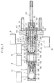
- Fig. 1 is a sectional view showing a first embodiment of the present invention. Referring to Fig. 1, elements identical or corresponding to those shown in Fig. 9 are indicated by the same reference numerals, thereby to omit redundant description.
- An input member 17 which is coupled with an input rod 20 is provided with a communication hole 47 extending through its central portion and an elongated hole 50 diametrically passing through the same.
- a pin 49 is fixedly mounted on a rear end portion of a boost piston 19. This pin 49 passes through the elongated hole 50 of the input member 17.
- a holder 51 is fixedly mounted on a rear end portion of a housing 1, to receive the input member 17 in the same.
- the input member 17 is in contact with a bottom wall portion 52 of the holder 51, to stop its rearward movement, as shown in Fig. 1.
- Difference from the prior art of Fig. 9 resides in this point.
- a clearance is axially defined between a shoulder portion 43 of the boost piston 19 and a seal cap 57 which is fixed to the housing 1.
- urging force for rearwardly pushing the boost piston 19 is so balanced with that for frontwardly pushing the boost piston 19 by boost pressure in a boost chamber 15 as to stop rearward movement of the boost piston 19.
- the boost piston 19 is rearwardly pushed by resultant force of urging force applied by a master spring 41 and that caused by auxiliary dynamic pressure acting on difference between sealing effective diameters of seals 29 and 30 (29 > 30) of the boost piston 19.
- an input hole 22 of the boost piston 19 axially coincides in position with an input edge 45 of a spool 18, whereby an input directional control valve defined by these elements is in a boundary position between open and closed states.
- the boost piston 19 slightly rearwardly moves from this state, the input directional control valve is opened so that the boost pressure in the boost chamber 15 is increased, whereby the input directional control valve immediately returns to the boundary portion.
- an output directional control valve which is defined by an output hole 24 of the boost piston 19 communicating with the boost chamber 15 and an output edge 46 of the spool 18 is closed.
- a plunger 32 of the first embodiment shown in Fig. 1 has no communication hole.
- the boost chamber 15 communicates with a reserve tank 9 through the output hole 24 of the boost piston 19, a communication hole 26 and a central communication hole 25 of the spool 18, a communication hole 47 of the input member 17, the outer peripheral portion of the boost piston 19 and a port 48 of the housing 1.
- the master piston 12 has an elongated hole 54 which diametrically passes through the same.
- a pin 53 is fixedly mounted on the housing 1, to pass through the elongated hole 54.
- the master piston 12 is further provided with a movable poppet valve disc 56 which can close a fluid passage 55 and a spring 58 urging the poppet valve disc 56 toward an opening direction.
- the rear end portion of the poppet valve disc 56 is in contact with a pin 53 which is fixed to the housing 1, thereby to open the passage 55.
- the poppet valve disc 56 is pushed by the spring 58, to close the passage 55.
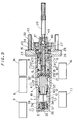
- Fig. 2 is a sectional view showing a second embodiment of the present invention, which is adapted to prevent such leakage of the working fluid.
- an output directional control valve includes a differential pressure regulating valve, which suppresses input pressure by the level of boost pressure applied during positioning of a boost piston 19 by boost piston positioning means and outputting the same.
- Other structure of this embodiment is identical to that of the first embodiment.
- an output directional control valve which is defined by a boost chamber 15, an output hole 24 of a boost piston 19 and an output edge 46 of a spool 18 includes a differential pressure regulating valve 59.
- Fig. 3 shows the differential pressure regulating valve 59 in an enlarged manner.
- This differential pressure regulating valve 59 comprises a valve seat 60 which is press-fitted in and fixed to the boost piston 19, a globe valve disc 61 which can be in contact with the valve seat 60 and a spring 62 for urging the globe valve disc 61 toward a closing direction.
- These elements are so selected that force applied by boost pressure to a sealing effective area between the valve seat 60 and the globe valve disc 61 is equalized to urging force of the spring 62.
- the differential pressure regulating valve 59 retains the boost pressure in the inactive state between the boost chamber 15 and the directional control valve defined by the output hole 24 and the output edge 46 of the spool 18. Thus, no auxiliary dynamic pressure is wasted by leakage of working fluid, dissimilarly to the first embodiment.
- Fig. 4 is a sectional view showing a third embodiment of the present invention.
- the third embodiment is also adapted to solve the problem of waste of auxiliary dynamic pressure by preventing leakage of working fluid.
- the differential pressure regulating valve 59 is added to the directional control valve defined by the output hole 24 of the boost piston 19 and the output edge 46 of the spool 18.
- these two valves are combined into a single valve.
- Other points of the third embodiment are substantially identical to those of the second embodiment.
- a holder 51 receiving an input member 17 and a rear end portion of a boost piston 19 is fixed to a housing 1 through a nut 71.
- the rear end portion of the input member 17 is in contact with the nut 71, thereby to stop rearward movement of the input member 17.
- Auxiliary dynamic pressure from an auxiliary power source 14 is introduced into a boost chamber 15 through a port 5 of the housing 1, the outer peripheral portion of the boost piston 19, an input hole 22, a small groove 28 of a spool 18 and a communication hole 23 of the boost piston 19.
- the third embodiment is similar to the first and second embodiments in this point. Difference from the first and second embodiments resides in that the auxiliary dynamic pressure from the auxiliary power source 14 is also introduced into an output directional control valve 64 which is defined within the spool 18 and the input member 17 through a communication hole 63.
- Fig. 5 is a plan view showing the structure of a part relating to the output directional control valve 64 shown in Fig. 4.
- Fig. 6 illustrates the output directional control valve 64 in an enlarged manner. The output directional control 64 is opened in the state shown in Figs. 4 and 5, while being closed in the state shown in Fig. 6.
- the spool 18 is provided in its rear end portion with a chamber 65 and a valve seat 66 which is fixed to the same.
- the chamber 65 contains a movable valve disc 67 which can be in contact with the valve seat 66 and a spring 68 for urging the movable valve disc 67 toward a closing direction.
- the input member 17 is provided in its forward end portion with a groove 69 diametrically passing through the same.
- a positioning pin 70 which passes through the groove 69, is fixedly mounted on the boost piston 19.
- the boost chamber 15 communicates with the reserve tank 9 through the communication hole 23, the small groove 28, the communication hole 63, the chamber 65, a communication hole 47, the outer peripheral portion of the boost piston 19 and a port 48 of the housing 1.
- Fig. 7 is a sectional view showing a fourth embodiment of the present invention.
- the input and output directional control valves are contained in the boost piston 19.
- a spool valve serving as an input/output directional control valve is parallelly provided in the exterior of a boost piston 104 and coupled with the same by a level mechanism, similarly to the apparatus disclosed in Japanese Patent Laying-Open Gazette No. 145655/1984.
- a housing 101 contains an input member 103 which is engaged with an input rod 102 and a boost piston 104.
- the input member 103 is relatively movably contained in the boost piston 104 in coaxial relation.
- An O-ring 107 is provided on the outer surface of the input member 103, in order to maintain fluid tightness between the input member 103 and the boost piston 104.
- Boost pressure generated in a boost chamber 108 acts on a seal portion of the O-ring 107.
- the input member 103 is rearwardly urged by the boost pressure acting on the sealing effective diameter of the O-ring 107.
- a stopper 106 is fixedly mounted on a housing 101, while a spring bearing 109 is fixedly mounted on the input rod 102.
- a return spring 105 is provided between the stopper 106 and the spring bearing 109.
- the input member 103 In an inactive state shown in Fig. 7 with no application of pedal force, the input member 103 is rearwardly urged by boost pressure which is required for positioning the boost piston 104, while being subjected to rearward urging force by the return spring 105.
- the input member 103 is in contact with the stopper 106 which is fixed to the housing 101, to stop rearward movement thereof.
- the housing 101 further contains a master piston 110 and a master spring 111 which is provided in a pressure chamber 115. Urging force of the master spring 111 is transmitted to the boost piston 104 through the master piston 110 and a rod 112. Seals 113 and 114 are provided in contact portions between the outer surface part of the boost piston 104 and the housing 101.
- the force of the master spring 111 for rearwardly urging the boost piston 104 is balanced with boost pressure acting on an area obtained by adding an effective area of the O-ring 107 to difference between sealing effective areas of the seals 113 and 114, thereby to rearwardly position the boost piston 104.
- the master piston 110 is provided therein with a fixed valve seat 116 and a valve disc 117 which can be in contact with the valve seat 116.
- the housing 101 further contains a sleeve 118, a spool 119 and a spool input member 120 in positions parallelly separated from the boost piston 104.
- the sleeve 118 is fixed to the housing 101.
- the spool 119 is coupled to the spool input member 120 to be relatively movable within the sleeve 118.
- a plug 121 is fixedly mounted on the housing 101.
- a first lever 122 and a second lever 124 are provided in order to connect the mechanism relating to the boost piston 104 and the input member 103 with the mechanism relating to the spool 119.
- the first lever 122 has an end supported by the plug 121 which is fixed to the housing 101 and another end supported by the input member 103.
- the first lever 122 is rotatable about a support point 123. Thus, when the input member 103 frontwardly moves from the state shown in the figure, the first lever 122 clockwisely rotates about the support point 123.
- the second lever 124 has an end supported by the spool input member 120 and another end supported by the boost piston 104.
- the second lever 124 is also rotatable about the support point 123. If the input member 103 relatively frontwardly moves with respect to the boost piston 104, the first lever 122 clockwisely rotates about the support point 123, as hereinabove described. A coupling point between the first lever 122 and the plug 121 remains immobile at this time, whereby the support point 123 frontwardly moves following the clockwise rotation of the first lever 122. Further, a coupling point between the second lever 124 and the boost piston 104 remains stopped, whereby the second lever 124 anticlockwisely rotates about the support point 123 following the frontward movement of the support point 123. In response to the anticlockwise rotation of the second lever 124, the spool input member 120 frontwardly moves and the spool 119 also relatively frontwardly moves within the sleeve 118.
- Fig. 8 shows a part relating to the spool 119 in an enlarged manner.
- the sleeve 118 is provided with an introduction hole 126 for introducing auxiliary dynamic pressure from an auxiliary power source 125 into the spool 119 and a communication hole 127 for connecting the spool 119 with a reserve tank 137.
- a passage 130 is provided in the internal surface of the sleeve 118, which is in contact with the outer surface of the spool 119.
- the spool 119 is provided with passages 129, 131 and 132. Further, a positioning member 133 is press-fitted in and fixed to the forward end of the spool 119. In addition, a movable valve disc 135 and a spring 134 are contained in the forward end portion of the spool 119. The spring 134 urges the movable valve disc 135 toward the positioning member 133. In correspondence to the movable valve disc 135, the sleeve 118 is provided with a valve seat 136.
- an input directional control valve which is defined by the introduction hole 126 of the sleeve 118 and an input edge 128 of the spool 119, is opened. Consequently, auxiliary dynamic pressure from the auxiliary power source 125 is introduced into the boost chamber 108 through the passages 129, 130, 131 and 132, whereby the boost pressure is increased.
- the movable valve disc 135 contained in the spool 119 and the valve seat 136 fixed to the sleeve 118 define an output directional control valve.
- This output directional control valve is closed in the inactive state shown in Fig. 7 and in such a state that the spool 119 relatively frontwardly moves with respect to the sleeve 118.
- the movable valve disc 135 is urged by the boost pressure to be in contact with the valve seat 136, thereby to prevent leakage of working fluid to the reserve tank 137.
- the master piston 110 When the boost pressure is increased and the boost piston 104 frontwardly moves following frontward movement of the input member 103, the master piston 110 also frontwardly moves through the rod 112.
- the valves seat 116 which is fixed to the master piston 110, is brought into contact with the valve disc 117, to close a fluid passage.
- communication between the pressure chamber 115 and the reserve tank 137 is cut off, whereby hydraulic pressure in the pressure chamber 115 is increased to be outputted through a port 138.
- Fig. 8 shows such a state that the spool 119 relatively rearwardly moves with respect to the sleeve 118.
- the input directional control valve defined by the introduction hole 126 and the input edge 128 is closed and the output directional valve defined by the movable valve disc 135 and the valve seat 136 is opened.
- the boost pressure is reduced at desire.
- the input directional control valve is in a critical position between open/closed states in the inactive state with no application of pedal force, thereby to prevent travel loss in an initial stage of braking operation. Further, no waste of auxiliary dynamic pressure is caused by leakage of the working fluid from the output directional control valve, similarly to the second and third embodiments.
Landscapes
- Engineering & Computer Science (AREA)
- Transportation (AREA)
- Mechanical Engineering (AREA)
- Braking Systems And Boosters (AREA)
- Regulating Braking Force (AREA)
Claims (3)
- Amplificateur hydraulique comportant une chambre d'amplification (15) et recevant une pression dynamique auxiliaire à partir d'une source de puissance auxiliaire (14) dans le fonctionnement d'une pédale de frein pour produire une pression d'amplification proportionnelle à la force de la pédale dans la chambre d'amplification, permettant ainsi d'assister la poussée d'un maître-cylindre (7) par la pression d'amplification, l'amplificateur hydraulique comprenant :
un piston d'amplification (19) ayant une portion dirigée sur son extrémité arrière en regard de la chambre d'amplification (15) et recevant la poussée de la pression d'amplification pour déplacer son côté d'extrémité avant permettant de solliciter sur l'avant un maître-piston (12) du maître-cylindre ;
un élément d'entrée (17) monté de façon relativement mobile par rapport au piston d'amplification pour la réception sur l'avant de l'entrée proportionnelle à la force de la pédale et la force de réaction de réception vers l'arrière étant proportionnelle à la pression d'amplification ;
des moyens de régulation de pression ayant une vanne de commande directionnelle d'entrée (22, 45) destinée à autoriser/couper la communication entre la chambre d'amplification (15) et la source de puissance auxiliaire (14) et une vanne de commande directionnelle de sortie (24, 26) destinée à autoriser/couper la communication entre la chambre d'amplification et un réservoir auxiliaire (9) étant ouvert à l'atmosphère pour augmenter la pression d'amplification en ouvrant la vanne de commande directionnelle d'entrée et en fermant la vanne de commande directionnelle de sortie et en ouvrant la vanne de commande directionnelle de sortie lorsque l'élément d'entrée est positionné relativement à l'avant d'une position prescrite par rapport au piston d'amplification tout en réduisant la pression d'amplification en fermant la vanne de commande directionnelle d'entrée lorsque l'élément d'entrée est positionné relativement à l'arrière d'une position prescrite par rapport au piston d'amplification ;
un logement (1) contenant le piston d'amplification (19), l'élément d'entrée (17) et le moyen de régulation de pression dans son intérieur ;
des moyens de positionnement d'élément d'entrée destinés à amener un côté d'extrémité arrière de l'élément d'entrée (17) en contact avec le logement ou un élément de butée (51) ancré sur le logement lorsque la force de la pédale est égale à zéro permettant de stopper le mouvement vers l'arrière de l'élément d'entrée, caractérisé par
des moyens de positionnement de piston d'amplification pour équilibrer la force de sollicitation de la pression d'amplification sur le piston d'amplification (19) avec la force de sollicitation destinée à pousser le piston d'amplification dans une direction arrière lorsque la force de la pédale est égale à zéro permettant ainsi de stopper le mouvement vers l'arrière du piston d'amplification. - Amplificateur hydraulique selon la revendication 1, dans lequel la vanne de commande directionnelle de sortie comprend une vanne de régulation de pression différentielle (59) destinée à supprimer la pression d'entrée par le niveau de la pression d'amplification appliquée lorsque le piston d'amplification est positionné par les moyens de positionnement du piston d'amplification et l'émission de celle-ci.
- Amplificateur hydraulique selon la revendication 1, dans lequel la vanne de commande directionnelle de sortie comprend :
un siège de vanne fixe (66),
un disque de vanne mobile (67) pouvant être fermé en étant en contact avec le siège de vanne fixe et recevant la pression d'amplification dans une direction de fermeture lorsqu'il est fermé, et
des moyens d'actionnement du disque de vanne mobile (68, 69, 70) destinés à amener le disque de vanne mobile dans une position fermée lorsque l'élément d'entrée est positionné relativement à l'avant d'une position prescrite par rapport au piston d'amplification et à amener le disque de vanne mobile dans une position ouverte lorsque l'élément d'entrée est positionné relativement à l'arrière d'une position prescrite par rapport au piston d'amplification tout en amenant le disque de vanne mobile dans une position fermée lorsque le piston d'amplification est positionné par les moyens de positionnement du piston d'amplification.
Applications Claiming Priority (2)
| Application Number | Priority Date | Filing Date | Title |
|---|---|---|---|
| JP62241793A JP2501601B2 (ja) | 1987-09-25 | 1987-09-25 | 液圧ブ―スタ |
| JP241793/87 | 1987-09-25 |
Publications (3)
| Publication Number | Publication Date |
|---|---|
| EP0308920A2 EP0308920A2 (fr) | 1989-03-29 |
| EP0308920A3 EP0308920A3 (en) | 1990-08-08 |
| EP0308920B1 true EP0308920B1 (fr) | 1993-06-30 |
Family
ID=17079598
Family Applications (1)
| Application Number | Title | Priority Date | Filing Date |
|---|---|---|---|
| EP88115547A Expired - Lifetime EP0308920B1 (fr) | 1987-09-25 | 1988-09-22 | Amplificateur hydraulique de force de freinage |
Country Status (5)
| Country | Link |
|---|---|
| US (1) | US4899640A (fr) |
| EP (1) | EP0308920B1 (fr) |
| JP (1) | JP2501601B2 (fr) |
| KR (1) | KR910001412B1 (fr) |
| DE (1) | DE3882107T2 (fr) |
Families Citing this family (6)
| Publication number | Priority date | Publication date | Assignee | Title |
|---|---|---|---|---|
| CN1147155C (zh) | 1998-12-14 | 2004-04-21 | 松下电器产业株式会社 | Dct运算装置 |
| JP2001260862A (ja) * | 2000-03-14 | 2001-09-26 | Aisin Seiki Co Ltd | 車両の液圧ブレーキ装置 |
| JP4702579B2 (ja) * | 2000-07-26 | 2011-06-15 | 株式会社アドヴィックス | 車両の液圧ブレーキ装置 |
| KR100721098B1 (ko) * | 2003-02-07 | 2007-05-22 | 주식회사 만도 | 차량용 브레이크 부스터 |
| US8522546B2 (en) * | 2008-06-26 | 2013-09-03 | The United States Of America, As Represented By The Administrator Of The U.S. Environmental Protection Agency | On-demand power brake system and method |
| US8763392B2 (en) | 2010-07-30 | 2014-07-01 | Robert Bosch Gmbh | Hydraulic booster vented input rod with poppet |
Family Cites Families (11)
| Publication number | Priority date | Publication date | Assignee | Title |
|---|---|---|---|---|
| GB545667A (en) * | 1940-12-16 | 1942-06-08 | Automotive Prod Co Ltd | Improvements in or relating to brakes for vehicles |
| DE2602050C3 (de) * | 1976-01-21 | 1983-11-03 | Volkswagenwerk Ag, 3180 Wolfsburg | Hydraulisches Verstärkerventil, insbesondere für eine hydraulische Bremsanlage eines Kraftfahrzeuges |
| US4179980A (en) * | 1976-04-03 | 1979-12-25 | Aisin Seiki Kabushiki Kaisha | Hydraulic brake booster |
| DE2837884C3 (de) * | 1977-09-01 | 1994-02-24 | Girling Ltd | Hydraulischer Kraftverstärker für eine Fahrzeug-Bremsanlage |
| GB2003564B (en) * | 1977-09-01 | 1982-02-17 | Girling Ltd | Hydraulic power boosters for vehicle braking systems |
| JPS56147159U (fr) * | 1980-04-08 | 1981-11-06 | ||
| DE3040561A1 (de) * | 1980-10-28 | 1982-05-27 | Alfred Teves Gmbh, 6000 Frankfurt | Fremdenergiegespeiste bremsschlupfregelanlage eines hydraulischen fahrzeugbremssystems |
| GB2102519B (en) * | 1981-07-04 | 1985-01-09 | Lucas Ind Plc | Combined hydraulic booster and master cylinder assemblies |
| DE3232051A1 (de) * | 1982-08-28 | 1984-03-01 | Alfred Teves Gmbh, 6000 Frankfurt | Verfahren zur ueberwachung und steuerung von fremdenergieversorgten hydraulischen bremsschlupfregelanlagen und vorrichtung zur druchfuehrung des verfahrens |
| SE455489B (sv) * | 1983-06-30 | 1988-07-18 | Teves Gmbh Alfred | Hydrauliskt bromssystem med en huvudcylinder och en hydraulisk bromskraftforsterkare forsedd med en pedalpaverkad dubbelsetesventil |
| US4642990A (en) * | 1984-03-13 | 1987-02-17 | Nissin Kogyo Kabushiki Kaisha | Master cylinder and oil-hydraulic booster assembly |
-
1987
- 1987-09-25 JP JP62241793A patent/JP2501601B2/ja not_active Expired - Lifetime
-
1988
- 1988-09-22 EP EP88115547A patent/EP0308920B1/fr not_active Expired - Lifetime
- 1988-09-22 DE DE88115547T patent/DE3882107T2/de not_active Expired - Fee Related
- 1988-09-23 KR KR1019880012292A patent/KR910001412B1/ko not_active Expired
- 1988-09-23 US US07/249,417 patent/US4899640A/en not_active Expired - Fee Related
Also Published As
| Publication number | Publication date |
|---|---|
| JP2501601B2 (ja) | 1996-05-29 |
| EP0308920A2 (fr) | 1989-03-29 |
| KR910001412B1 (ko) | 1991-03-05 |
| DE3882107T2 (de) | 1993-10-07 |
| EP0308920A3 (en) | 1990-08-08 |
| JPS6483448A (en) | 1989-03-29 |
| KR890004926A (ko) | 1989-05-10 |
| US4899640A (en) | 1990-02-13 |
| DE3882107D1 (de) | 1993-08-05 |
Similar Documents
| Publication | Publication Date | Title |
|---|---|---|
| US4274518A (en) | Brake force regulator for a motorcycle hydraulic brake system | |
| US4229050A (en) | Brake force regulator for a motorcycle hydraulic brake system | |
| JPS599973Y2 (ja) | ブレ−キブ−スタ付マスタシリンダ | |
| US3834277A (en) | Hydraulic servo unit for automotive braking system | |
| US4312182A (en) | Hydraulic control for automobile brakes | |
| EP0308920B1 (fr) | Amplificateur hydraulique de force de freinage | |
| US4110985A (en) | Dual power brake booster | |
| PL184053B1 (pl) | Urządzenie hamujące ze wspomaganiem, ze zmiennym stosunkiem wspomagania i ze zredukowaną histerezą | |
| US20020014379A1 (en) | Brake apparatus | |
| GB1502109A (en) | Power servomotor for a vehicle braking system | |
| US5038564A (en) | Pulsator-operated valving with reaction chamber accumulator for hydraulic booster system | |
| JPH0357760A (ja) | 液圧ブースタ装置 | |
| US4754604A (en) | Hydraulic brake booster with tubular conduit return spring | |
| US4255932A (en) | Tandem master cylinder | |
| US4265490A (en) | Pressure control valve for a vehicle hydraulic brake system | |
| US4474004A (en) | Power-operated boosters | |
| JP3521258B2 (ja) | 気圧式倍力装置 | |
| US4524584A (en) | Brake booster | |
| US6978710B2 (en) | Pneumatic booster | |
| GB2230576A (en) | Hydraulic braking system | |
| US6655513B2 (en) | Hydraulic brake device for a vehicle | |
| CA1319897C (fr) | Soupape de remplissage rapide incorporee au cylindre principal d'un systeme de freinage | |
| US6513883B2 (en) | Hydraulic brake for a vehicle | |
| GB2200419A (en) | Vehicle hydraulic systems | |
| US5878651A (en) | Tandem vacuum brake booster |
Legal Events
| Date | Code | Title | Description |
|---|---|---|---|
| PUAI | Public reference made under article 153(3) epc to a published international application that has entered the european phase |
Free format text: ORIGINAL CODE: 0009012 |
|
| AK | Designated contracting states |
Kind code of ref document: A2 Designated state(s): DE GB |
|
| RAP1 | Party data changed (applicant data changed or rights of an application transferred) |
Owner name: SUMITOMO ELECTRIC INDUSTRIES, LIMITED |
|
| PUAL | Search report despatched |
Free format text: ORIGINAL CODE: 0009013 |
|
| AK | Designated contracting states |
Kind code of ref document: A3 Designated state(s): DE GB |
|
| 17P | Request for examination filed |
Effective date: 19900910 |
|
| 17Q | First examination report despatched |
Effective date: 19920311 |
|
| GRAA | (expected) grant |
Free format text: ORIGINAL CODE: 0009210 |
|
| AK | Designated contracting states |
Kind code of ref document: B1 Designated state(s): DE GB |
|
| REF | Corresponds to: |
Ref document number: 3882107 Country of ref document: DE Date of ref document: 19930805 |
|
| PLBE | No opposition filed within time limit |
Free format text: ORIGINAL CODE: 0009261 |
|
| STAA | Information on the status of an ep patent application or granted ep patent |
Free format text: STATUS: NO OPPOSITION FILED WITHIN TIME LIMIT |
|
| 26N | No opposition filed | ||
| PGFP | Annual fee paid to national office [announced via postgrant information from national office to epo] |
Ref country code: GB Payment date: 19960913 Year of fee payment: 9 |
|
| PG25 | Lapsed in a contracting state [announced via postgrant information from national office to epo] |
Ref country code: GB Free format text: LAPSE BECAUSE OF NON-PAYMENT OF DUE FEES Effective date: 19970922 |
|
| GBPC | Gb: european patent ceased through non-payment of renewal fee |
Effective date: 19970922 |
|
| PGFP | Annual fee paid to national office [announced via postgrant information from national office to epo] |
Ref country code: DE Payment date: 19980925 Year of fee payment: 11 |
|
| PG25 | Lapsed in a contracting state [announced via postgrant information from national office to epo] |
Ref country code: DE Free format text: LAPSE BECAUSE OF NON-PAYMENT OF DUE FEES Effective date: 20000701 |