EP0308986B1 - Press à balles de fibres - Google Patents
Press à balles de fibres Download PDFInfo
- Publication number
- EP0308986B1 EP0308986B1 EP88115821A EP88115821A EP0308986B1 EP 0308986 B1 EP0308986 B1 EP 0308986B1 EP 88115821 A EP88115821 A EP 88115821A EP 88115821 A EP88115821 A EP 88115821A EP 0308986 B1 EP0308986 B1 EP 0308986B1
- Authority
- EP
- European Patent Office
- Prior art keywords
- film
- bale
- baling press
- base plate
- plate
- Prior art date
- Legal status (The legal status is an assumption and is not a legal conclusion. Google has not performed a legal analysis and makes no representation as to the accuracy of the status listed.)
- Expired - Lifetime
Links
Images
Classifications
-
- B—PERFORMING OPERATIONS; TRANSPORTING
- B65—CONVEYING; PACKING; STORING; HANDLING THIN OR FILAMENTARY MATERIAL
- B65B—MACHINES, APPARATUS OR DEVICES FOR, OR METHODS OF, PACKAGING ARTICLES OR MATERIALS; UNPACKING
- B65B27/00—Bundling particular articles presenting special problems using string, wire, or narrow tape or band; Baling fibrous material, e.g. peat, not otherwise provided for
- B65B27/12—Baling or bundling compressible fibrous material, e.g. peat
- B65B27/125—Baling or bundling compressible fibrous material, e.g. peat and wrapping or bagging
-
- B—PERFORMING OPERATIONS; TRANSPORTING
- B30—PRESSES
- B30B—PRESSES IN GENERAL
- B30B9/00—Presses specially adapted for particular purposes
- B30B9/30—Presses specially adapted for particular purposes for baling; Compression boxes therefor
- B30B9/3003—Details
Definitions
- the invention relates to a fiber baler with at least one press plate which can be covered with a piece of film-like packaging material and which is assigned to a press box casing which is preferably completely closed.
- a fiber baler of this type is known from DE-A-29 11 958. Since the steel strips or the like must not come into contact with the fibers to tie the bale, the bale must be covered with packaging material all around before the reinforcement. For this purpose, both the lower and the upper press ram are coated with a piece of packaging material before the pressing process, then the bale is pressed, then the press box jacket is removed upwards while maintaining the pressing pressure and finally wrapped horizontally with a wider packaging material piece all around to end the packaging process .
- a prerequisite for packaging to ensure satisfactory packaging is not only that the film covers the bale all around, but also that the film surrounds the bale without wrinkles, so that both the surfaces and the edges of the bale look neatly packaged.
- This ram design is very expensive to manufacture. However, it also requires a number of movements only for wrapping the bale all around with a film, which are quite time-consuming and ultimately prone to failure. In this respect, it is more advantageous if the bottom and the press ram are not divided, but consist of one piece.
- the lower ram i.e. the bottom plate of the press box, made of a flat plate, which is interspersed with lacing grooves for the reinforcement process.
- devices are arranged in the base plate which are intended to cause the edge portions of the film to bend upwards around the bale after the press box casing has been pulled off. These devices consist of fingers that are supposed to slide upwards around the film edge sections.
- the invention has for its object to develop a fiber baler, in which the film itself by the design of the press plate itself after removing the press box casing on the bale, whereby stretching, pivoting or upward moving fingers are substantially avoided .
- the press plate for aligning the film is trough-shaped with wall parts protruding all around from the floor.
- the edge sections of the film are oriented upwards when the press box is filled with the material to be pressed. A part of the edge sections of the film is thus already directed upwards when the press box casing is removed, so that the remaining edge sections of the film bent downward from the lower end face of the press box casing automatically point upwards after the press box casing has been removed.
- the film is automatically directed downwards.
- the pressing pressure that acts vertically downwards also creates a force in the direction of the press box walls. This pressure is released when the press casing is removed, whereupon the fiber material will expand one or two cm outwards, depending on the fiber properties. If the press box casing is now pulled off, the fiber material on the upper edge of the trough will bulge outwards beyond this edge, with the result that the film is pressed horizontally outwards from the tendency directed from the bottom upwards. It is a particular idea of the invention to avoid this horizontal outward bending of the film by making the base plate larger in its trough-shaped cross section than the cross sectional area of the press box casing.
- the fiber material will not only expand outwards in the area of the press box jacket previously arranged there, but also in the area of the trough-shaped opening of the base plate, in such a way that, after the stretching process, the bale receives exactly the shape that the tub already has in its construction. So that the film lies evenly upwards from the flat surface perpendicular to the bale and can now be easily covered by the film to be wrapped horizontally, without the need for additional directional fingers or the like.
- the edge sections of the film are not too long and too heavy. This applies in particular to the longer long sides of the bale, which are later held by the steel strips or the like.
- a longer section of film is necessary on the narrower end faces, which are generally not reinforced, in order to permanently cover the bale with the film.
- this longer section of film cannot be oriented upwards over its entire length due to the measure according to the invention.
- the invention provides that a foil sheet metal sheet is attached to the outside of the two narrow sides of the base plate, closely adjacent to the outer wall, so that it can be moved up and down. So there should be no fingers attached to the base plate, but only a pivotable foil sheet which can be moved through an inclined plane, for example when the pressed bale is moved into the reinforcement station.
- the lower press plate of a central press is also the bottom of a press box.
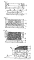
- a press box thus consists of the base plate 1 and the all-round closed press box jacket 2, which is detachably connected to the base plate 1.
- the bottom plate 1 has for pulling the packaging tapes or the like.
- Fig. 4 visible lacing grooves 3, which are open to the bale 9 so that the threaded tapes lie after lifting the pressure through these openings on the bale.
- the base plate 1 is trough-like in the area of the receptacle of the fiber material 7, and not only to give the bale 9 a round shape in the area of the longitudinal edges, but also around the piece of packaging material 4 for covering of the bale 9 is placed on its underside before merging with the press box casing 2 on the press plate 1 by means not shown here, to give a pre-orientation upwards in the direction of the bale 9.
- the inner edges of the tub 6 are expediently provided with an inner radius.
- the press ram not shown, can also be designed to be open in the manner of a trough.
- the press box casing 2 moves downward from above and is supported on the base plate 1 in order to be firmly connected to it by folding devices, not shown here.
- the inner surface of the tub 6 is larger than the cross section of the interior of the press box casing 2.
- the lower end 5 of the inner wall of the press box casing 2 dips into the tub 6 at a short distance from the tub 6, so that the piece of packaging material 4 is placed evenly on the bottom of the base plate 1 and is well fixed there even when the jug is filled with fiber material 7.
- the more stable outer wall 8 of the press box casing 2 is supported outside the tub 6 on the base plate 1, so that the weight of the perss box casing 2 is not supported on the narrower wall 6 'of the tub 6. For this reason, the press box jacket extends deeper outside of the tub 6, ie inside the tub 6, and is connected there with grippers to the base plate 1.
- the press box now migrates together with the press box jacket and press box bottom, that is to say the base plate, to the central press, where the final pressing process of the fiber material 7 to the bale 9 shown in FIG. 3 is carried out. So that the bale 9 can be packed all around with prepacking material, it is necessary to remove the press box casing 2 from the bale 9. This takes place in the fiber baler according to the invention in that the press box casing is pulled upwards in accordance with the arrows shown in FIG. Since the baling pressure acts unchanged by the baling punch, not shown, the fiber material of the bale 9 expands to the sides that are released are. These are the four side surfaces of the bale 9.
- the fiber material in the trough 6 can also expand on all four sides. This has the advantage that the fiber material of the bale 9 is not pressed over the upper edge of the tub 6 during expansion and the film 4 would otherwise press horizontally outwards there. Due to the construction of the base plate 1, the fiber material of the bale 9 can also expand outwards in the region of the tub 6 and then, after the stretching process, receives exactly the figuration that was previously determined by the tub 6. The bale 9 then extends vertically upward from the side walls of the tub 6, as a result of which the packaging material piece 4 is given an upward orientation. This is also shown in Figure 3.
- FIG. 4 shows one side of the bale 9 in the area of the front side of the bale 9. For such a long edge section 10 ′ of the packaging material piece 4, the pre-orientation of the film upwards due to the design of the tub 6 would not be sufficient to place the packaging material on the bale 9.
- a foil sheet metal sheet 11 is attached to the base plate 1 close to the outer wall and is displaceable up and down.
- the pivot point of the sheet metal sheet 11 is provided on the sliding carriage 12 on the joint 13.
- a spring 14 in this articulated arm 15 ensures that the foil sheet metal 11 is in constant contact with the bale 9.
- the articulated arm 15 automatically pivoted upwards when the bale is moved into the packaging station about the joint 13, as a result of which the foil sheet 11 places the edge section 10 'of the packaging material piece 4 upwards, namely against the end face of the bale 9.
- the foil sheet 11 can also rest against the bale 9 during the reinforcement process without interfering with this reinforcement process.
- the articulated arm 15 then moves slowly over the downward inclined plane 18 on the opposite side and is thereby pulled out of the space between the film section 10 and the film piece which has meanwhile been wrapped horizontally and re-welded.
Landscapes
- Engineering & Computer Science (AREA)
- Mechanical Engineering (AREA)
- Auxiliary Devices For And Details Of Packaging Control (AREA)
- Basic Packing Technique (AREA)
- Storage Of Harvested Produce (AREA)
Claims (7)
Applications Claiming Priority (2)
| Application Number | Priority Date | Filing Date | Title |
|---|---|---|---|
| DE3732390 | 1987-09-25 | ||
| DE19873732390 DE3732390A1 (de) | 1987-09-25 | 1987-09-25 | Faserballenpresse |
Publications (2)
| Publication Number | Publication Date |
|---|---|
| EP0308986A1 EP0308986A1 (fr) | 1989-03-29 |
| EP0308986B1 true EP0308986B1 (fr) | 1991-01-16 |
Family
ID=6336906
Family Applications (1)
| Application Number | Title | Priority Date | Filing Date |
|---|---|---|---|
| EP88115821A Expired - Lifetime EP0308986B1 (fr) | 1987-09-25 | 1988-09-26 | Press à balles de fibres |
Country Status (4)
| Country | Link |
|---|---|
| US (1) | US4959948A (fr) |
| EP (1) | EP0308986B1 (fr) |
| JP (1) | JPH01148496A (fr) |
| DE (2) | DE3732390A1 (fr) |
Families Citing this family (10)
| Publication number | Priority date | Publication date | Assignee | Title |
|---|---|---|---|---|
| US5252275A (en) * | 1991-03-07 | 1993-10-12 | Weyerhauser Company | Method of densifying crosslinked fibers |
| EP0420071B1 (fr) * | 1989-09-29 | 1994-06-08 | Mitsubishi Jukogyo Kabushiki Kaisha | Méthode d'emballage sous compression et appareil de liage d'objets à emballer |
| DE3939944C2 (de) * | 1989-12-02 | 1994-08-04 | Lindemann Maschfab Gmbh | Ballenpresse mit einem Schnürnuten aufweisenden Preßstempel |
| US5174198A (en) * | 1990-10-31 | 1992-12-29 | Weyerhaeuser Company | Method for packaging and shipping fiber materials |
| US5213030A (en) * | 1990-10-31 | 1993-05-25 | Weyerhaeuser Company | Method for packaging and shipping fiber materials |
| ITFI20010135A1 (it) * | 2001-07-13 | 2003-01-13 | Gualchierani Textile Automatio | Pressa per la formazione di balle di materiale tessile od altro,con dispositivo di rivestimento mediante un telo |
| US7306093B2 (en) * | 2003-02-14 | 2007-12-11 | Eastman Chemical Company | Packages, packaging systems, methods for packaging and apparatus for packaging |
| US20050284775A1 (en) * | 2003-02-14 | 2005-12-29 | Mclaughlin Michael R | Packages, packaging systems, methods for packaging, and apparatuses for packaging |
| JP5165012B2 (ja) | 2010-02-22 | 2013-03-21 | 三菱電機株式会社 | 樹脂封止形電子制御装置及びその製造方法 |
| WO2015058383A1 (fr) * | 2013-10-24 | 2015-04-30 | 陈子虎 | Appareil de pressage de pousses de bambou |
Family Cites Families (15)
| Publication number | Priority date | Publication date | Assignee | Title |
|---|---|---|---|---|
| US159378A (en) * | 1875-02-02 | Improvement in methods of fastening cotton-bales | ||
| US2731777A (en) * | 1956-01-24 | wollersheim | ||
| US1840053A (en) * | 1930-03-27 | 1932-01-05 | Prince Seymour | Method of packaging |
| US2621589A (en) * | 1942-05-20 | 1952-12-16 | Dubois Georges Albert | Outfit for the packing of dehydrated fruits and vegetables or other applications |
| US2790287A (en) * | 1951-06-19 | 1957-04-30 | Kraft Foods Co | Packaging machine |
| US3246443A (en) * | 1961-09-07 | 1966-04-19 | Gen Tire & Rubber Co | Foam cushion material packaging |
| US3407562A (en) * | 1965-05-11 | 1968-10-29 | Gen Electric | Capacitor assembly method |
| DE1586954C3 (de) * | 1967-04-08 | 1978-08-10 | Titan Verpackungssysteme Gmbh, 5830 Schwelm | Vorrichtung zum Umreifen von expansionsfähigen Gütern, wie Preßballen |
| US3972155A (en) * | 1969-09-24 | 1976-08-03 | Mahaffy & Harder Engineering Company | Packaging techniques for semi-rigid packages |
| AU495693B2 (en) * | 1975-07-24 | 1977-01-27 | Hardwicke-Etter Company | Automatic bale wrapping apparatus |
| DE2736316A1 (de) * | 1977-08-12 | 1979-02-22 | Hoechst Ag | Verfahren und vorrichtung zum pressen und verpacken von fadenkabeln |
| DE2911958C2 (de) * | 1979-03-27 | 1993-10-07 | Hoechst Ag | Verfahren zum Verpacken von faserigem Gut in Ballen sowie geeignete Preßanordnung dazu |
| US4688369A (en) * | 1980-05-23 | 1987-08-25 | Oscar Mayer Foods Corporation | Apparatus and method for pressure resizing of products |
| JPS6264705A (ja) * | 1985-09-10 | 1987-03-23 | 三菱重工業株式会社 | 高速箱詰装置の前後フラツプ折込装置 |
| US4685391A (en) * | 1986-01-16 | 1987-08-11 | The Scientific Ecology Group, Inc. | Remotely controlled multishaped container compacting press |
-
1987
- 1987-09-25 DE DE19873732390 patent/DE3732390A1/de not_active Withdrawn
-
1988
- 1988-09-26 JP JP63239097A patent/JPH01148496A/ja active Pending
- 1988-09-26 EP EP88115821A patent/EP0308986B1/fr not_active Expired - Lifetime
- 1988-09-26 US US07/249,296 patent/US4959948A/en not_active Expired - Fee Related
- 1988-09-26 DE DE8888115821T patent/DE3861577D1/de not_active Expired - Lifetime
Also Published As
| Publication number | Publication date |
|---|---|
| JPH01148496A (ja) | 1989-06-09 |
| DE3861577D1 (de) | 1991-02-21 |
| DE3732390A1 (de) | 1989-04-06 |
| US4959948A (en) | 1990-10-02 |
| EP0308986A1 (fr) | 1989-03-29 |
Similar Documents
| Publication | Publication Date | Title |
|---|---|---|
| DE3405182A1 (de) | Presse zum packen von zusammendrueckbarem material | |
| DE3323090A1 (de) | Eierschachtel | |
| EP0528893B1 (fr) | Procede et dispositif pour appliquer une feuille de recouvrement autour d'une balle compressee | |
| EP0308986A1 (fr) | Press à balles de fibres | |
| DE2558248B2 (de) | Filterpresse | |
| EP0308985B1 (fr) | Dispositif pour la mise en balle de matière fibreuse ainsi que presse pour la mise en balle de matière fibreuse | |
| DE2645540B2 (de) | Vorrichtung zum Errichten eines aus miteinander zu verbindenden Platten bestehenden zylindrischen Behälters | |
| DE2900134A1 (de) | Deckel mit selbsttaetig schliessender oeffnung zum befuellen von zur aufnahme von losem material bestimmten behaeltern | |
| DE2648748A1 (de) | Auslegeranordnung | |
| DE2657106C3 (de) | Durch teleskopartiges Auseinanderziehen von ineinandergeschachtelten Elementen gebildete Wand | |
| DE10303508B4 (de) | Separiereinrichtung einer Rollenbahn für Stückgüter | |
| DE2514515C3 (de) | Presse zum Biegen von Blechen | |
| DE3340205A1 (de) | Gabelscherengreifer | |
| DE2523043C2 (de) | Ballenpresse | |
| DE2528715C3 (de) | Vorgefertigtes Bauelement aus Stahlbeton zur Herstellung einer Winkelstützmauer od.dgl. | |
| DE4408845C2 (de) | Fertigungsanlage für Mauerelemente | |
| DE2638562A1 (de) | Vorrichtung zur herstellung von behaelterpacks, insbesondere von behaelterpacks fuer pastoese lebensmittel | |
| EP0334094A2 (fr) | Dispositif d'injection d'une partie en matière synthétique sur un tube en papier au moyen d'une pièce de support | |
| DE2348655A1 (de) | Formvorrichtung zum herstellen von grossvolumigen koerpern | |
| DE102017119092A1 (de) | Kasten-Ballenpresse mit Schiebetür sowie Verfahren zum Betreiben einer solchen Kastenpresse. | |
| DE10390331B4 (de) | Anordnung zum Umschnüren von Ballen in einer Ballenpresse | |
| DE2035053B2 (de) | Presse zur Herstellung von Formteilen | |
| DE2516418A1 (de) | Schalung fuer isolierfuge o.dgl. zwischenraum | |
| DE3917166C2 (fr) | ||
| DE2928111A1 (de) | Ballenpresse fuer textilfasern |
Legal Events
| Date | Code | Title | Description |
|---|---|---|---|
| PUAI | Public reference made under article 153(3) epc to a published international application that has entered the european phase |
Free format text: ORIGINAL CODE: 0009012 |
|
| 17P | Request for examination filed |
Effective date: 19890120 |
|
| AK | Designated contracting states |
Kind code of ref document: A1 Designated state(s): BE DE IT |
|
| 17Q | First examination report despatched |
Effective date: 19900611 |
|
| GRAA | (expected) grant |
Free format text: ORIGINAL CODE: 0009210 |
|
| AK | Designated contracting states |
Kind code of ref document: B1 Designated state(s): BE DE IT |
|
| ITF | It: translation for a ep patent filed | ||
| REF | Corresponds to: |
Ref document number: 3861577 Country of ref document: DE Date of ref document: 19910221 |
|
| PG25 | Lapsed in a contracting state [announced via postgrant information from national office to epo] |
Ref country code: BE Effective date: 19910930 |
|
| PLBE | No opposition filed within time limit |
Free format text: ORIGINAL CODE: 0009261 |
|
| STAA | Information on the status of an ep patent application or granted ep patent |
Free format text: STATUS: NO OPPOSITION FILED WITHIN TIME LIMIT |
|
| 26N | No opposition filed | ||
| BERE | Be: lapsed |
Owner name: FLEISSNER MASCHINENFABRIK A.G. Effective date: 19910930 |
|
| PGFP | Annual fee paid to national office [announced via postgrant information from national office to epo] |
Ref country code: DE Payment date: 19970903 Year of fee payment: 10 |
|
| PG25 | Lapsed in a contracting state [announced via postgrant information from national office to epo] |
Ref country code: DE Free format text: LAPSE BECAUSE OF NON-PAYMENT OF DUE FEES Effective date: 19990701 |
|
| PG25 | Lapsed in a contracting state [announced via postgrant information from national office to epo] |
Ref country code: IT Free format text: LAPSE BECAUSE OF NON-PAYMENT OF DUE FEES;WARNING: LAPSES OF ITALIAN PATENTS WITH EFFECTIVE DATE BEFORE 2007 MAY HAVE OCCURRED AT ANY TIME BEFORE 2007. THE CORRECT EFFECTIVE DATE MAY BE DIFFERENT FROM THE ONE RECORDED. Effective date: 20050926 |