EP0334094A2 - Dispositif d'injection d'une partie en matière synthétique sur un tube en papier au moyen d'une pièce de support - Google Patents
Dispositif d'injection d'une partie en matière synthétique sur un tube en papier au moyen d'une pièce de support Download PDFInfo
- Publication number
- EP0334094A2 EP0334094A2 EP19890103955 EP89103955A EP0334094A2 EP 0334094 A2 EP0334094 A2 EP 0334094A2 EP 19890103955 EP19890103955 EP 19890103955 EP 89103955 A EP89103955 A EP 89103955A EP 0334094 A2 EP0334094 A2 EP 0334094A2
- Authority
- EP
- European Patent Office
- Prior art keywords
- edge
- paper tube
- support part
- flat
- injection core
- Prior art date
- Legal status (The legal status is an assumption and is not a legal conclusion. Google has not performed a legal analysis and makes no representation as to the accuracy of the status listed.)
- Granted
Links
- 238000002347 injection Methods 0.000 title claims abstract description 46
- 239000007924 injection Substances 0.000 title claims abstract description 46
- 239000007788 liquid Substances 0.000 claims description 22
- 238000000465 moulding Methods 0.000 claims description 11
- 239000007921 spray Substances 0.000 claims description 10
- 239000011092 plastic-coated paper Substances 0.000 claims description 2
- 238000013461 design Methods 0.000 description 8
- 230000012447 hatching Effects 0.000 description 5
- 239000011324 bead Substances 0.000 description 4
- 238000005452 bending Methods 0.000 description 4
- 238000004519 manufacturing process Methods 0.000 description 4
- 238000003754 machining Methods 0.000 description 3
- 238000000034 method Methods 0.000 description 3
- 238000004806 packaging method and process Methods 0.000 description 3
- 238000007789 sealing Methods 0.000 description 3
- 238000005507 spraying Methods 0.000 description 3
- 238000011835 investigation Methods 0.000 description 2
- 238000012856 packing Methods 0.000 description 2
- 238000004873 anchoring Methods 0.000 description 1
- 230000015572 biosynthetic process Effects 0.000 description 1
- 239000012876 carrier material Substances 0.000 description 1
- 230000006735 deficit Effects 0.000 description 1
- 238000009795 derivation Methods 0.000 description 1
- 238000009826 distribution Methods 0.000 description 1
- 238000005516 engineering process Methods 0.000 description 1
- 239000000835 fiber Substances 0.000 description 1
- 238000001746 injection moulding Methods 0.000 description 1
- 239000000463 material Substances 0.000 description 1
- 238000010137 moulding (plastic) Methods 0.000 description 1
- 229920000642 polymer Polymers 0.000 description 1
- 238000012360 testing method Methods 0.000 description 1
- 230000003313 weakening effect Effects 0.000 description 1
Images


Classifications
-
- B—PERFORMING OPERATIONS; TRANSPORTING
- B29—WORKING OF PLASTICS; WORKING OF SUBSTANCES IN A PLASTIC STATE IN GENERAL
- B29C—SHAPING OR JOINING OF PLASTICS; SHAPING OF MATERIAL IN A PLASTIC STATE, NOT OTHERWISE PROVIDED FOR; AFTER-TREATMENT OF THE SHAPED PRODUCTS, e.g. REPAIRING
- B29C45/00—Injection moulding, i.e. forcing the required volume of moulding material through a nozzle into a closed mould; Apparatus therefor
- B29C45/14—Injection moulding, i.e. forcing the required volume of moulding material through a nozzle into a closed mould; Apparatus therefor incorporating preformed parts or layers, e.g. injection moulding around inserts or for coating articles
- B29C45/14336—Coating a portion of the article, e.g. the edge of the article
-
- B—PERFORMING OPERATIONS; TRANSPORTING
- B29—WORKING OF PLASTICS; WORKING OF SUBSTANCES IN A PLASTIC STATE IN GENERAL
- B29C—SHAPING OR JOINING OF PLASTICS; SHAPING OF MATERIAL IN A PLASTIC STATE, NOT OTHERWISE PROVIDED FOR; AFTER-TREATMENT OF THE SHAPED PRODUCTS, e.g. REPAIRING
- B29C45/00—Injection moulding, i.e. forcing the required volume of moulding material through a nozzle into a closed mould; Apparatus therefor
- B29C45/14—Injection moulding, i.e. forcing the required volume of moulding material through a nozzle into a closed mould; Apparatus therefor incorporating preformed parts or layers, e.g. injection moulding around inserts or for coating articles
- B29C45/14598—Coating tubular articles
Definitions
- the invention relates to a device for molding a plastic part onto a plastic-coated paper tube, in particular a lid onto the paper sleeve of a liquid pack, with a spray core and an outer shape that at least partially encompasses it.
- Such spraying devices are already known and are described below in connection with a packaging machine, in which paper coated with plastic on both sides in web form is pulled off a roll, separated and formed into a paper tube with a round cross section via a longitudinal sealing seam, which also has a cross section round mandrel is pushed on as a spray core and ends with its edge in the spray position in the mold space of the tool (spray core and outer mold) such that the heated, liquid plastic flows into the mold space and completely encompasses the round end edge of the paper tube.
- the paper sleeve in the known machine is closed on one side by the lid, because the lid is made of plastic without a carrier material and, for example, also has the pouring opening at the same time.
- the cover is anchored to the front edge of the paper tube, is supported on it and at the same time seals the open cut surface of this front edge. If you cut a paper web coated on both sides with plastic, then along the cut edge, which after the formation of the sleeve becomes the circular end edge, there is an unprotected edge coated without plastic, which must be protected against the ingress of liquid, because otherwise the liquid enters the paper fibers penetrates between the plastic layers and the packing is destroyed from this cut edge.
- the known injection molding machine therefore has such a molding space that the upper round end edge of the paper tube is not at the edge of the molding space but inside the same ends with the result that the plastic that later completely fills the molding space not only bears on the free end edge, which was the cut surface, but also on both sides next to it, thus sealing the upper edge of the paper tube in a liquid-tight manner.
- the packaging machine for producing liquid packs that are at least partially round in cross section worked satisfactorily in this way.
- the only difference to the round pack for the tool is that the mandrel also becomes quadrangular in cross-section by forming four outer planes, and the correspondingly designed paper sleeve is pushed onto this cuboid mandrel in a comparable position. For the rest, it was believed that there would be no changes in the spraying technique.
- the invention was therefore based on the object to improve the injection device of the type mentioned in such a way that the flat walls of the tube do not bend when the paper tube is square in cross section and the injection point is reliably set everywhere.
- the upper flat edge of the paper tube is one piece after being pushed onto the mandrel protrudes far beyond the upper outer edge of the mandrel, namely in order to protrude into the mold space, is supported from the outside by the wall of the outer mold and now also from the inside according to the invention by the supporting part.
- the support part has the shape of a plate which occupies part of the cross-sectional profile between the injection core and the outer shape, and if the outer end face of the support part is flat and lies parallel to the tube wall in such a way that it lies on the flat edge of the paper tube can be created.
- the end face and also the edge face of a mandrel or injection core is partially shaped by machining, so that straight edges and lines are preferred both in recesses and in elevations on such a workpiece.
- the design of the support part as a plate meets this requirement and therefore facilitates production.
- the support part protruding from the edge surface fills a fraction of the cross-sectional profile of this mold space; by no means the entire cross section of the molding space at the location of the support part. Namely, it must also be ensured in the area of the support part that the free end face of the paper tube, which has lost all edge protection due to the cut, is completely sealed and encapsulated with plastic when the cover is molded on.
- the support part can, however, occupy such a large part of the cross-sectional profile of the molding space that the tensile forces or holding forces between the upper edge of the paper tube and the cover are absent, since the support part is missing, while ensuring the tightness mentioned (edge protection) takes up only a fraction of the entire edge surface, so that the adjacent surfaces are sufficient to compensate for or take over the missing support forces only in the area of the support part.
- the upper edge of the paper tube can be placed directly on the support part and supported, as the name suggests.
- the outer flat end face of the support part opens into the outer plane of the injection-molded core, which is square in cross-section, and lies flush with it, and in the direction of the straight outer edge has a length of 1/90 to 1/20, preferably 1/70 to 1 / 40 the length of the outer edge. If the length of the outer edge is, for example, 70 mm, then a length of the flat end surface of the support part of 1 mm, as seen in the direction of the straight outer edge, is sufficient to ensure effective support of the flat edge of the paper tube.
- the paper tube Due to the flush arrangement of the outer flat end surface of the support part to the outer plane of the injection core and by the opening of the end surface in this outer plane, the paper tube can be pushed onto the injection core or pulled down from it without any impairment, as if no support parts were provided.
- the support is particularly useful if, according to the invention, the outer flat end surface of the support part is rectangular and has a height which is approximately equal to the distance between the straight outer edge of the injection core and the first shoulder of the outer shape.
- the first shoulder of the outer shape mentioned here limits the molding space which will later be filled with plastic to the outside and below the edge of the lid, for example when looking at the lid of the finished, closed liquid pack from above.
- the square end face is covered by the "radial" or “horizontal" outer flange of the lid, which for reasons of strength and tightness extends beyond the free end of the upper edge of the paper tube and is welded to the outside of the plastic layer of the paper tube.
- the invention is advantageously designed in such a way that the edge surface connecting each of the four outer planes of the injection core with its end face is formed from at least two sub-planes that intersect along a central edge, and that the support part has at least the lower sub-plane lying between the central edge and the upper outer edge is attached.
- the upper outer edge of the injection core is referred to here as the "upper" outer edge, because one of about vertically upstanding mandrel or spray core and therefore assumes the end face of the same as "arranged above”.
- the generally flat end face, which forms the inside of the packing lid, is thus connected to the outer plane via the said edge surface.
- the edge surface between the outer plane of the injection core and its end surface could also be formed by curved surfaces and the like, provided that only the molding space around the upper edge of the paper tube is designed in this way, that the above-mentioned features and requirements are met, that is to say the free cut edge, the upper end edge of the tube, is encapsulated in a liquid-tight manner (edge protection) and collar-like injection beads, preferably attached to the inside of the liquid pack, are welded to the edge of the paper tube, so that there is also a mechanical holder of the plastic part (lid of the pack) on the paper tube (the paper sleeve) is guaranteed.
- the edge surface consists of two sub-planes which run in a strip-like manner parallel to the upper outer edge, the lower sub-plane lying between the upper outer edge and a central edge and the upper strip-like sub-plane extending between the central edge and the end surface edge .
- Seen in the profile direction of the support part i.e. Seen in the direction of the upper outer edge, the central edge, the upper outer edge and also the end face edge, which are all three straight, represent points, the partial planes being represented by the connecting lines of these points.
- edge area is planes; if they are curved lines, they are the curved surfaces mentioned above. So planes are preferred, and here it is possible that both sub-planes again lie in one plane, which then form a flat edge surface; in a preferred embodiment, the central edge is somewhat outside, so that two sub-planes set at different angles to one another form the edge surface.
- the shape of the edge surface of the injection core can preferably have the shape of a house roof, the support part according to the invention being attached like a dormer window to at least one of the two part levels.
- the window area of the dormer then corresponds to the outer flat end surface of the support part, because this surface lies parallel and flush with the outer plane of the injection core.
- the rear surface which runs at an angle to this flat end face of the support part and corresponds to the roof area of the dormer, can extend to the end face edge, but can also end in the area of the upper part level or even at the middle edge. While the outer end surface of the support member should be flat to provide the appropriate support for the flat edge of the paper tube, the surface of the support member corresponding to the roof portion of the dormer need not be flat.
- the support part Except for the outer flat end surface of the support part, its design is otherwise uncritical, provided the support part does not take up too much volume in order not to weaken the mechanical tensile and compressive forces mentioned of the plastic which connects the lid to the paper tube of the later liquid pack.
- a useful design of the support parts is plate shape.
- a groove can be made in the edge surface of the injection core and / or beyond the edges thereof by a simple machining movement (planing machine) in such a way that a suitably shaped plate is inserted and welded tight.
- Another manufacturing method could be the support also form part or alternatively weld onto the edge surface without providing a groove in the injection core.
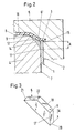
- the mandrel or injection core which is square in cross section, is designated by 4, the external shape by 5 and the support part by 6 net.
- the injection core 4 has four outer planes, of which only the front or right outer plane 7 is shown in FIGS. 1 and 2. On the end face or “above”, the injection core 4 is delimited by the end face 8, which at the end edge 9 merges into the edge face generally designated 10 and which has the straight, upper outer edge 11 in common with the outer plane 7. If the edge surface 10 consists of an upper (12) partial plane and a lower partial plane (13), then they intersect in the central edge 14.
- the support part 6 in the form of the plate is shown in perspective in FIG. 3 and shown in FIG. 1 installed.
- This part 6 mainly depends on the outer flat end surface 17, the surface of which is given by the length 1 (FIG. 1) and height h (FIG. 1).
- the area 17 'shown in Figure 3' is larger than the flat surface 17, because it is extended by the in the body of the injection core behind the outer plane 7 Sene part, so that the total height of the surface 17 'is denoted by H.
- H can be equal to h or greater than h, but certainly not less than h.
- the upper surface 18 of the support part 6, which corresponds to the roof surface of the dormer, is flat in this embodiment and opens at the top in the direction of the end surface 8 in the end edge 9.
- the cross-sectional profile of the support member 6 is created with a simple hatching and designated 6 ', the direction of this single hatching is at a different angle than the hatching of the edge 2 of the paper tube 1. From Figure 2 it can thus be seen that which part in the area of the support part 6 the dormer-like elevation under the plastic cover 16 occupies.
- the support part has a length 1 of 1 to 2 mm, for example 2 mm. Only in this area is the finished plastic lid 16 of the liquid pack lacking the volume 6 'which results from the hatched area 6' in FIG. 2 'multiplied by the length 1.
- the parts of the support part 6 shown in broken lines in FIG. 1 are variable.
- the lower front edge 20 of the support part 6 according to FIG. 3 can be somewhat higher while reducing the height H, and the rear lower edge 21 can also be closer to the rear upper edge 22, which lies in the front edge 9 as shown in FIG. 1 , have come closer.
- the area between the edges 21 and 22 could be completely omitted if, for example, the supporting part 6 is welded to it like a dormer window without being immersed in the edge area 10.
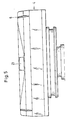
- FIG. 4 The top view of FIG. 4 on the injection core 4 shows the pouring opening 23 in the upper region and a supporting part 6 on the adjacent edge at the top, while three supporting parts 6 are provided along the two lower edges.
- the flow channels 24 for the liquid plastic during the injection process are also indicated in FIG. In the areas of the support part 6 there are small recesses in the plastic bead arranged on the inside of the finished package.
- FIG. 5 shows a side view of the head of the injection core when looking down from FIG. 4, which is why the pouring device 23 can be seen in the middle. At a distance to the right and left of this one can see two support parts 6, which appear in perspective in this representation.
- the head of a spray core 4 ' is shown for another embodiment, in which three recesses 25 are made in the shape of a groove at the top, where support parts are later inserted and fastened.
- the support part can also be integrally formed or welded on. It should be emphasized again that a real preferred alternative is the molding or finishing from a single piece.
- the edge surface 10 or the upper sub-plane 12 and the lower sub-plane 13 can then be machined out by machining so that the support part 6 remains.
- a support part 6 in the form of a plate is assumed, as shown in FIG. 3, which is why in FIG. 1 this plate-shaped support part 6 is drawn as more or less embedded in the injection core 4.
Landscapes
- Engineering & Computer Science (AREA)
- Manufacturing & Machinery (AREA)
- Mechanical Engineering (AREA)
- Injection Moulding Of Plastics Or The Like (AREA)
- Moulds For Moulding Plastics Or The Like (AREA)
- Details Or Accessories Of Spraying Plant Or Apparatus (AREA)
- Infusion, Injection, And Reservoir Apparatuses (AREA)
- Sampling And Sample Adjustment (AREA)
- Buffer Packaging (AREA)
- Catching Or Destruction (AREA)
- Closures For Containers (AREA)
Priority Applications (1)
| Application Number | Priority Date | Filing Date | Title |
|---|---|---|---|
| AT89103955T ATE95109T1 (de) | 1988-03-19 | 1989-03-07 | Vorrichtung zum anspritzen eines kunststoffteiles an einen papiertubus unter verwendung eines abstuetzteiles. |
Applications Claiming Priority (2)
| Application Number | Priority Date | Filing Date | Title |
|---|---|---|---|
| DE3809275A DE3809275A1 (de) | 1988-03-19 | 1988-03-19 | Vorrichtung zum anspritzen eines kunststoffteiles an einen papiertubus unter verwendung eines abstuetzteiles |
| DE3809275 | 1988-03-19 |
Publications (3)
| Publication Number | Publication Date |
|---|---|
| EP0334094A2 true EP0334094A2 (fr) | 1989-09-27 |
| EP0334094A3 EP0334094A3 (fr) | 1991-01-30 |
| EP0334094B1 EP0334094B1 (fr) | 1993-09-29 |
Family
ID=6350174
Family Applications (1)
| Application Number | Title | Priority Date | Filing Date |
|---|---|---|---|
| EP89103955A Expired - Lifetime EP0334094B1 (fr) | 1988-03-19 | 1989-03-07 | Dispositif d'injection d'une partie en matière synthétique sur un tube en papier au moyen d'une pièce de support |
Country Status (10)
| Country | Link |
|---|---|
| US (1) | US4952130A (fr) |
| EP (1) | EP0334094B1 (fr) |
| JP (1) | JPH01275112A (fr) |
| CN (1) | CN1018989B (fr) |
| AT (1) | ATE95109T1 (fr) |
| AU (1) | AU615993B2 (fr) |
| BR (1) | BR8901241A (fr) |
| CA (1) | CA1328967C (fr) |
| DE (2) | DE3809275A1 (fr) |
| ES (1) | ES2043916T3 (fr) |
Cited By (2)
| Publication number | Priority date | Publication date | Assignee | Title |
|---|---|---|---|---|
| EP0443369A3 (en) * | 1990-02-20 | 1992-12-16 | Tetra Alfa Holdings S.A. | Package for flowable products with reccesses for handling and process for its production |
| EP2234785A4 (fr) * | 2007-12-18 | 2015-04-15 | Tetra Laval Holdings & Finance | Appareil et procédé de moulage d'une pièce d'un récipient d'emballage |
Families Citing this family (5)
| Publication number | Priority date | Publication date | Assignee | Title |
|---|---|---|---|---|
| US5593631A (en) * | 1989-06-30 | 1997-01-14 | Sumitomo Chemical Company, Limited | Method for molding resin articles |
| SE501660C2 (sv) * | 1993-08-31 | 1995-04-10 | Tetra Laval Holdings & Finance | Anordning vid termoformning av hällpip |
| JP3706840B2 (ja) * | 2002-03-28 | 2005-10-19 | 森六株式会社 | シール付き外装部材の製造方法 |
| SE532765C2 (sv) * | 2008-06-19 | 2010-04-06 | Tetra Laval Holdings & Finance | Metod och anordning för formsprutning vid tillverkning av förpackningsbehållare |
| FR3000422B1 (fr) * | 2012-12-28 | 2015-07-03 | Plastic Omnium Cie | Plancher en matiere plastique pour vehicule automobile avec inserts metalliques de ferrage |
Family Cites Families (15)
| Publication number | Priority date | Publication date | Assignee | Title |
|---|---|---|---|---|
| US2100985A (en) * | 1935-10-19 | 1937-11-30 | Kenneth B Cope | Molding apparatus |
| US3330006A (en) * | 1963-10-30 | 1967-07-11 | American Can Co | Apparatus for molding of container headpiece and closure therefor |
| US3829055A (en) * | 1972-07-21 | 1974-08-13 | Gates Rubber Co | Mold for locating transverse reinforcements in endless track |
| US3991146A (en) * | 1974-04-01 | 1976-11-09 | Imperial Chemical Industries Limited | Method of encapsulating an insert in plastics material by injection molding |
| GB1504526A (en) * | 1974-05-28 | 1978-03-22 | Airfix Ind Ltd | Containers |
| DE2947621C2 (de) * | 1979-11-26 | 1984-07-26 | WOCO Franz-Josef Wolf & Co, 6483 Bad Soden-Salmünster | Formwerkzeug zum Umspritzen eines eingelegten Einlegeteiles, mit einem Kantendichtungsprofil |
| JPS6058822A (ja) * | 1983-09-12 | 1985-04-05 | Dainippon Printing Co Ltd | 複合容器成形方法 |
| JPS6058821A (ja) * | 1983-09-12 | 1985-04-05 | Dainippon Printing Co Ltd | 複合容器成形方法 |
| US4580962A (en) * | 1984-06-20 | 1986-04-08 | Chicago Rawhide Mfg. Co. | Seal mold and method |
| GB2171046A (en) * | 1985-02-14 | 1986-08-20 | Metal Box Plc | Containers |
| JPS62238717A (ja) * | 1986-04-09 | 1987-10-19 | Nissei Plastics Ind Co | チユ−ブ容器の成形方法 |
| IL82714A0 (en) * | 1986-08-13 | 1987-11-30 | Predrag Pesovic | Silent valve |
| US4803030A (en) * | 1986-12-09 | 1989-02-07 | Alps Electric Co., Ltd. | Method of molding case for push-button switch |
| JPH0658821A (ja) * | 1992-08-06 | 1994-03-04 | Nec Corp | 温度センサー |
| JPH0658822A (ja) * | 1992-08-07 | 1994-03-04 | Nippon Telegr & Teleph Corp <Ntt> | 温度センサ |
-
1988
- 1988-03-19 DE DE3809275A patent/DE3809275A1/de active Granted
-
1989
- 1989-03-07 EP EP89103955A patent/EP0334094B1/fr not_active Expired - Lifetime
- 1989-03-07 ES ES89103955T patent/ES2043916T3/es not_active Expired - Lifetime
- 1989-03-07 DE DE89103955T patent/DE58905722D1/de not_active Expired - Fee Related
- 1989-03-07 AT AT89103955T patent/ATE95109T1/de not_active IP Right Cessation
- 1989-03-15 JP JP1061058A patent/JPH01275112A/ja active Pending
- 1989-03-15 US US07/324,299 patent/US4952130A/en not_active Expired - Fee Related
- 1989-03-17 AU AU31470/89A patent/AU615993B2/en not_active Ceased
- 1989-03-17 BR BR898901241A patent/BR8901241A/pt not_active IP Right Cessation
- 1989-03-18 CN CN89101653.8A patent/CN1018989B/zh not_active Expired
- 1989-03-20 CA CA000594229A patent/CA1328967C/fr not_active Expired - Fee Related
Cited By (2)
| Publication number | Priority date | Publication date | Assignee | Title |
|---|---|---|---|---|
| EP0443369A3 (en) * | 1990-02-20 | 1992-12-16 | Tetra Alfa Holdings S.A. | Package for flowable products with reccesses for handling and process for its production |
| EP2234785A4 (fr) * | 2007-12-18 | 2015-04-15 | Tetra Laval Holdings & Finance | Appareil et procédé de moulage d'une pièce d'un récipient d'emballage |
Also Published As
| Publication number | Publication date |
|---|---|
| CN1035979A (zh) | 1989-10-04 |
| DE3809275A1 (de) | 1989-10-05 |
| AU615993B2 (en) | 1991-10-17 |
| ATE95109T1 (de) | 1993-10-15 |
| EP0334094A3 (fr) | 1991-01-30 |
| DE3809275C2 (fr) | 1991-08-14 |
| CN1018989B (zh) | 1992-11-11 |
| EP0334094B1 (fr) | 1993-09-29 |
| DE58905722D1 (de) | 1993-11-04 |
| AU3147089A (en) | 1989-09-21 |
| CA1328967C (fr) | 1994-05-03 |
| JPH01275112A (ja) | 1989-11-02 |
| ES2043916T3 (es) | 1994-01-01 |
| BR8901241A (pt) | 1989-11-07 |
| US4952130A (en) | 1990-08-28 |
Similar Documents
| Publication | Publication Date | Title |
|---|---|---|
| DE1925853A1 (de) | Behaelter | |
| DE3323090A1 (de) | Eierschachtel | |
| DE2406300A1 (de) | Verfahren und rohteil zur herstellung eines gegenstandes | |
| DE3015112C2 (de) | Vorrichtung zum Herstellen eines flüssigkeitsdichten Behälters | |
| DE2123472A1 (de) | Unter Anwendung von Spritzguß hergestellter Behälter sowie Verfahren zu seiner Herstellung | |
| EP0028299A2 (fr) | Conteneur pour liquides avec ouvertures de déversement et d'admission d'air | |
| DE2640775A1 (de) | Flexibler profilstreifen mit u-foermigem querschnitt zum dichten, fuehren oder abdecken | |
| EP0334094B1 (fr) | Dispositif d'injection d'une partie en matière synthétique sur un tube en papier au moyen d'une pièce de support | |
| EP0144736A2 (fr) | Emballage pour liquides | |
| DE2714288C2 (de) | Vorrichtung zum Ultraschall-Schweißen eines rechteckigen Endverschlusses eines Pappkartons | |
| DE69001800T2 (de) | Behälterverschluss mit Metallkörper und Kunststoff-Griffteil. | |
| AT397071B (de) | Behälterzuschnitt aus faltbarem flachmaterial | |
| EP0384037A2 (fr) | Emballage pour liquides pourvu de propriétés aseptiques et procédé de fabrication | |
| EP0308986B1 (fr) | Press à balles de fibres | |
| DE3002452C2 (de) | Platte aus Holzwerkstoff, z.B. Tischplatte für Garten-, Camping- oder Küchentische | |
| EP0401546B1 (fr) | Emballage pour produits fluides et son procédé de fabrication | |
| DE2915166C2 (fr) | ||
| DE20311719U1 (de) | Kunststofftube | |
| CH630309A5 (en) | Packaging container | |
| DE3203834C2 (de) | Putz-Schutzdeckel aus Kunststoff für Unterputzdosen elektrischer Leitungen | |
| DE10228316A1 (de) | Behältnis zum Aufnehmen mindestens eines Stiftes | |
| CH680279A5 (fr) | ||
| DE3222180A1 (de) | Packung fuer fliessfaehige fuellgueter und verfahren zu deren herstellung | |
| DE2938669A1 (de) | Hohlkoerper | |
| CH321359A (de) | Zusammendrückbarer Behälter für Flüssigkeiten oder Pasten und Verfahren zur Herstellung desselben |
Legal Events
| Date | Code | Title | Description |
|---|---|---|---|
| PUAI | Public reference made under article 153(3) epc to a published international application that has entered the european phase |
Free format text: ORIGINAL CODE: 0009012 |
|
| AK | Designated contracting states |
Kind code of ref document: A2 Designated state(s): AT BE CH DE ES FR GB IT LI NL SE |
|
| RAP1 | Party data changed (applicant data changed or rights of an application transferred) |
Owner name: TETRA PAK HOLDINGS & FINANCE S.A. |
|
| PUAL | Search report despatched |
Free format text: ORIGINAL CODE: 0009013 |
|
| AK | Designated contracting states |
Kind code of ref document: A3 Designated state(s): AT BE CH DE ES FR GB IT LI NL SE |
|
| RHK1 | Main classification (correction) |
Ipc: B29C 45/14 |
|
| 17P | Request for examination filed |
Effective date: 19910322 |
|
| RAP1 | Party data changed (applicant data changed or rights of an application transferred) |
Owner name: TETRA PAK HOLDINGS S.A. |
|
| 17Q | First examination report despatched |
Effective date: 19920511 |
|
| RAP3 | Party data changed (applicant data changed or rights of an application transferred) |
Owner name: TETRA ALFA HOLDINGS S.A. |
|
| ITF | It: translation for a ep patent filed | ||
| GRAA | (expected) grant |
Free format text: ORIGINAL CODE: 0009210 |
|
| AK | Designated contracting states |
Kind code of ref document: B1 Designated state(s): AT BE CH DE ES FR GB IT LI NL SE |
|
| REF | Corresponds to: |
Ref document number: 95109 Country of ref document: AT Date of ref document: 19931015 Kind code of ref document: T |
|
| ET | Fr: translation filed | ||
| REF | Corresponds to: |
Ref document number: 58905722 Country of ref document: DE Date of ref document: 19931104 |
|
| GBT | Gb: translation of ep patent filed (gb section 77(6)(a)/1977) |
Effective date: 19931015 |
|
| REG | Reference to a national code |
Ref country code: CH Ref legal event code: PFA Free format text: TETRA LAVAL HOLDINGS & FINANCE S.A. |
|
| RAP2 | Party data changed (patent owner data changed or rights of a patent transferred) |
Owner name: TETRA LAVAL HOLDINGS & FINANCE S.A. |
|
| REG | Reference to a national code |
Ref country code: ES Ref legal event code: FG2A Ref document number: 2043916 Country of ref document: ES Kind code of ref document: T3 |
|
| NLT2 | Nl: modifications (of names), taken from the european patent patent bulletin |
Owner name: TETRA LAVAL HOLDINGS & FINANCE S.A. TE PULLY, ZWIT |
|
| NLXE | Nl: other communications concerning ep-patents (part 3 heading xe) |
Free format text: PAT.BUL.24/93 CORR.:TETRA LAVAL HOLDINGS & FINANCE S.A.,PULLY, ZWITSERLAND PAT.BUL.04/94 SHOULD BE DELETED |
|
| PLBE | No opposition filed within time limit |
Free format text: ORIGINAL CODE: 0009261 |
|
| STAA | Information on the status of an ep patent application or granted ep patent |
Free format text: STATUS: NO OPPOSITION FILED WITHIN TIME LIMIT |
|
| 26N | No opposition filed | ||
| EAL | Se: european patent in force in sweden |
Ref document number: 89103955.4 |
|
| PGFP | Annual fee paid to national office [announced via postgrant information from national office to epo] |
Ref country code: SE Payment date: 19980219 Year of fee payment: 10 |
|
| PGFP | Annual fee paid to national office [announced via postgrant information from national office to epo] |
Ref country code: FR Payment date: 19980221 Year of fee payment: 10 |
|
| PGFP | Annual fee paid to national office [announced via postgrant information from national office to epo] |
Ref country code: NL Payment date: 19980223 Year of fee payment: 10 Ref country code: DE Payment date: 19980223 Year of fee payment: 10 Ref country code: AT Payment date: 19980223 Year of fee payment: 10 |
|
| PGFP | Annual fee paid to national office [announced via postgrant information from national office to epo] |
Ref country code: GB Payment date: 19980226 Year of fee payment: 10 |
|
| PGFP | Annual fee paid to national office [announced via postgrant information from national office to epo] |
Ref country code: CH Payment date: 19980309 Year of fee payment: 10 |
|
| PGFP | Annual fee paid to national office [announced via postgrant information from national office to epo] |
Ref country code: ES Payment date: 19980317 Year of fee payment: 10 |
|
| PGFP | Annual fee paid to national office [announced via postgrant information from national office to epo] |
Ref country code: BE Payment date: 19980320 Year of fee payment: 10 |
|
| PG25 | Lapsed in a contracting state [announced via postgrant information from national office to epo] |
Ref country code: GB Free format text: LAPSE BECAUSE OF NON-PAYMENT OF DUE FEES Effective date: 19990307 Ref country code: AT Free format text: LAPSE BECAUSE OF NON-PAYMENT OF DUE FEES Effective date: 19990307 |
|
| PG25 | Lapsed in a contracting state [announced via postgrant information from national office to epo] |
Ref country code: SE Free format text: LAPSE BECAUSE OF NON-PAYMENT OF DUE FEES Effective date: 19990308 Ref country code: ES Free format text: LAPSE BECAUSE OF THE APPLICANT RENOUNCES Effective date: 19990308 |
|
| PG25 | Lapsed in a contracting state [announced via postgrant information from national office to epo] |
Ref country code: LI Free format text: LAPSE BECAUSE OF NON-PAYMENT OF DUE FEES Effective date: 19990331 Ref country code: CH Free format text: LAPSE BECAUSE OF NON-PAYMENT OF DUE FEES Effective date: 19990331 Ref country code: BE Free format text: LAPSE BECAUSE OF NON-PAYMENT OF DUE FEES Effective date: 19990331 |
|
| BERE | Be: lapsed |
Owner name: S.A. TETRA ALFA HOLDINGS Effective date: 19990331 |
|
| PG25 | Lapsed in a contracting state [announced via postgrant information from national office to epo] |
Ref country code: NL Free format text: LAPSE BECAUSE OF NON-PAYMENT OF DUE FEES Effective date: 19991001 |
|
| GBPC | Gb: european patent ceased through non-payment of renewal fee |
Effective date: 19990307 |
|
| EUG | Se: european patent has lapsed |
Ref document number: 89103955.4 |
|
| REG | Reference to a national code |
Ref country code: CH Ref legal event code: PL |
|
| PG25 | Lapsed in a contracting state [announced via postgrant information from national office to epo] |
Ref country code: FR Free format text: LAPSE BECAUSE OF NON-PAYMENT OF DUE FEES Effective date: 19991130 |
|
| NLV4 | Nl: lapsed or anulled due to non-payment of the annual fee |
Effective date: 19991001 |
|
| EUG | Se: european patent has lapsed |
Ref document number: 89103955.4 |
|
| REG | Reference to a national code |
Ref country code: FR Ref legal event code: ST |
|
| PG25 | Lapsed in a contracting state [announced via postgrant information from national office to epo] |
Ref country code: DE Free format text: LAPSE BECAUSE OF NON-PAYMENT OF DUE FEES Effective date: 20000101 |
|
| REG | Reference to a national code |
Ref country code: ES Ref legal event code: FD2A Effective date: 20010402 |
|
| PG25 | Lapsed in a contracting state [announced via postgrant information from national office to epo] |
Ref country code: IT Free format text: LAPSE BECAUSE OF NON-PAYMENT OF DUE FEES;WARNING: LAPSES OF ITALIAN PATENTS WITH EFFECTIVE DATE BEFORE 2007 MAY HAVE OCCURRED AT ANY TIME BEFORE 2007. THE CORRECT EFFECTIVE DATE MAY BE DIFFERENT FROM THE ONE RECORDED. Effective date: 20050307 |