EP0309072A1 - Cleaning apparatus - Google Patents
Cleaning apparatus Download PDFInfo
- Publication number
- EP0309072A1 EP0309072A1 EP88303059A EP88303059A EP0309072A1 EP 0309072 A1 EP0309072 A1 EP 0309072A1 EP 88303059 A EP88303059 A EP 88303059A EP 88303059 A EP88303059 A EP 88303059A EP 0309072 A1 EP0309072 A1 EP 0309072A1
- Authority
- EP
- European Patent Office
- Prior art keywords
- trolley
- brush
- pack
- fluid
- cleaning apparatus
- Prior art date
- Legal status (The legal status is an assumption and is not a legal conclusion. Google has not performed a legal analysis and makes no representation as to the accuracy of the status listed.)
- Withdrawn
Links
- 238000004140 cleaning Methods 0.000 title claims description 28
- 239000012530 fluid Substances 0.000 claims abstract description 53
- 230000000295 complement effect Effects 0.000 claims description 6
- 230000002093 peripheral effect Effects 0.000 claims description 3
- 239000000306 component Substances 0.000 description 8
- 230000008901 benefit Effects 0.000 description 6
- 238000010276 construction Methods 0.000 description 5
- 230000009471 action Effects 0.000 description 4
- 239000000463 material Substances 0.000 description 4
- 238000010168 coupling process Methods 0.000 description 3
- 238000005859 coupling reaction Methods 0.000 description 3
- 230000007246 mechanism Effects 0.000 description 3
- 239000004033 plastic Substances 0.000 description 3
- 229920003023 plastic Polymers 0.000 description 3
- 238000000465 moulding Methods 0.000 description 2
- 238000007493 shaping process Methods 0.000 description 2
- 235000004443 Ricinus communis Nutrition 0.000 description 1
- 208000036366 Sensation of pressure Diseases 0.000 description 1
- 238000006243 chemical reaction Methods 0.000 description 1
- 238000002485 combustion reaction Methods 0.000 description 1
- 230000008878 coupling Effects 0.000 description 1
- 230000001747 exhibiting effect Effects 0.000 description 1
- 239000000203 mixture Substances 0.000 description 1
- 230000009467 reduction Effects 0.000 description 1
- 230000000717 retained effect Effects 0.000 description 1
- 238000007790 scraping Methods 0.000 description 1
- 239000004071 soot Substances 0.000 description 1
- 230000007704 transition Effects 0.000 description 1
- 230000003245 working effect Effects 0.000 description 1
Images



Classifications
-
- A—HUMAN NECESSITIES
- A47—FURNITURE; DOMESTIC ARTICLES OR APPLIANCES; COFFEE MILLS; SPICE MILLS; SUCTION CLEANERS IN GENERAL
- A47L—DOMESTIC WASHING OR CLEANING; SUCTION CLEANERS IN GENERAL
- A47L11/00—Machines for cleaning floors, carpets, furniture, walls, or wall coverings
- A47L11/40—Parts or details of machines not provided for in groups A47L11/02 - A47L11/38, or not restricted to one of these groups, e.g. handles, arrangements of switches, skirts, buffers, levers
-
- A—HUMAN NECESSITIES
- A47—FURNITURE; DOMESTIC ARTICLES OR APPLIANCES; COFFEE MILLS; SPICE MILLS; SUCTION CLEANERS IN GENERAL
- A47L—DOMESTIC WASHING OR CLEANING; SUCTION CLEANERS IN GENERAL
- A47L1/00—Cleaning windows
- A47L1/06—Hand implements
- A47L1/08—Hand implements with provision for supplying liquids, e.g. cleaning agents
-
- A—HUMAN NECESSITIES
- A47—FURNITURE; DOMESTIC ARTICLES OR APPLIANCES; COFFEE MILLS; SPICE MILLS; SUCTION CLEANERS IN GENERAL
- A47L—DOMESTIC WASHING OR CLEANING; SUCTION CLEANERS IN GENERAL
- A47L11/00—Machines for cleaning floors, carpets, furniture, walls, or wall coverings
- A47L11/02—Floor surfacing or polishing machines
- A47L11/10—Floor surfacing or polishing machines motor-driven
- A47L11/14—Floor surfacing or polishing machines motor-driven with rotating tools
- A47L11/18—Floor surfacing or polishing machines motor-driven with rotating tools the tools being roll brushes
- A47L11/185—Floor surfacing or polishing machines motor-driven with rotating tools the tools being roll brushes with supply of cleaning agents
-
- A—HUMAN NECESSITIES
- A47—FURNITURE; DOMESTIC ARTICLES OR APPLIANCES; COFFEE MILLS; SPICE MILLS; SUCTION CLEANERS IN GENERAL
- A47L—DOMESTIC WASHING OR CLEANING; SUCTION CLEANERS IN GENERAL
- A47L11/00—Machines for cleaning floors, carpets, furniture, walls, or wall coverings
- A47L11/40—Parts or details of machines not provided for in groups A47L11/02 - A47L11/38, or not restricted to one of these groups, e.g. handles, arrangements of switches, skirts, buffers, levers
- A47L11/4036—Parts or details of the surface treating tools
- A47L11/4041—Roll shaped surface treating tools
-
- A—HUMAN NECESSITIES
- A47—FURNITURE; DOMESTIC ARTICLES OR APPLIANCES; COFFEE MILLS; SPICE MILLS; SUCTION CLEANERS IN GENERAL
- A47L—DOMESTIC WASHING OR CLEANING; SUCTION CLEANERS IN GENERAL
- A47L11/00—Machines for cleaning floors, carpets, furniture, walls, or wall coverings
- A47L11/40—Parts or details of machines not provided for in groups A47L11/02 - A47L11/38, or not restricted to one of these groups, e.g. handles, arrangements of switches, skirts, buffers, levers
- A47L11/4063—Driving means; Transmission means therefor
- A47L11/4069—Driving or transmission means for the cleaning tools
-
- A—HUMAN NECESSITIES
- A47—FURNITURE; DOMESTIC ARTICLES OR APPLIANCES; COFFEE MILLS; SPICE MILLS; SUCTION CLEANERS IN GENERAL
- A47L—DOMESTIC WASHING OR CLEANING; SUCTION CLEANERS IN GENERAL
- A47L11/00—Machines for cleaning floors, carpets, furniture, walls, or wall coverings
- A47L11/40—Parts or details of machines not provided for in groups A47L11/02 - A47L11/38, or not restricted to one of these groups, e.g. handles, arrangements of switches, skirts, buffers, levers
- A47L11/4075—Handles; levers
-
- A—HUMAN NECESSITIES
- A47—FURNITURE; DOMESTIC ARTICLES OR APPLIANCES; COFFEE MILLS; SPICE MILLS; SUCTION CLEANERS IN GENERAL
- A47L—DOMESTIC WASHING OR CLEANING; SUCTION CLEANERS IN GENERAL
- A47L11/00—Machines for cleaning floors, carpets, furniture, walls, or wall coverings
- A47L11/40—Parts or details of machines not provided for in groups A47L11/02 - A47L11/38, or not restricted to one of these groups, e.g. handles, arrangements of switches, skirts, buffers, levers
- A47L11/408—Means for supplying cleaning or surface treating agents
- A47L11/4088—Supply pumps; Spraying devices; Supply conduits
-
- B—PERFORMING OPERATIONS; TRANSPORTING
- B08—CLEANING
- B08B—CLEANING IN GENERAL; PREVENTION OF FOULING IN GENERAL
- B08B1/00—Cleaning by methods involving the use of tools
- B08B1/30—Cleaning by methods involving the use of tools by movement of cleaning members over a surface
- B08B1/32—Cleaning by methods involving the use of tools by movement of cleaning members over a surface using rotary cleaning members
- B08B1/34—Cleaning by methods involving the use of tools by movement of cleaning members over a surface using rotary cleaning members rotating about an axis parallel to the surface
Definitions
- the invention relates to cleaning apparatus.
- the invention is specifically applicable to cleaning apparatus comprising a hand-held motor-driven brush rotating, in use, to spread cleaning fluid on a surface to be cleaned by the brush, and incorporating means to supply the fluid to the brush head.
- Cleaning apparatus of the kind defined in the preceding paragraph will be referred to as cleaning apparatus of the kind in question.
- ROTABRUSH apparatus are ground-standing units. They comprise a wheeled trolley on which are mounted a motor drive and a fluid pump. In use, the pump draws fluid from a fluid canister - which may also be carried on the trolley - and supplies it to the brush head.
- the motor preferively a mains-supply-powered electric motor, transmits rotary movement to the brush head via an elongate drive line. And the fluid supply line and the drive line are both sufficiently flexible to allow a user of the apparatus to move the brush about the surface to be cleaned.
- any attempt to provide a drive line from the apparatus to such a remote location is either impractical or literally technically impossible. If, as in the case of a powered access platform, the brush-holding operator might move substantial distances over and above the normal arc of sweep of the brush relative to his body, from the ground-standing trolley, an appropriate flexible drive line from trolley-mounted motor to remote brush head might well be ruled out. The need to manhandle a fluid supply line over such a distance, and under such working conditions, might similarly negate the successful working of the apparatus. And the general inconvenience, even danger, of attempting to work with excessively long multiple lines under such conditions is enormously increased.
- the invention takes as its starting point the known ROTABRUSH apparatus discussed above. It sets out to provide an improved version of such apparatus which, unlike the known apparatus, can practically be used at locations which are remote from the trolley and may vary considerably, during a cleaning cycle, in distance and/or height from the ground-standing trolley; whilst retaining the advantages of the known trolley-based design.
- Such a unit has two alternative modes of use. It can be used as a ground-standing unit, just like the existing ROTABRUSH apparatus. Or alternatively the user can take the back-pack unit off the trolley, proceed with it to the location that he wants to clean, and proceed to work with a drive line which need not be increased in length. He has only the back-pack unit to take with him up ladders, onto scaffolds, up in powered access platforms, and the like. And if - as in a presently preferred embodiment of the invention - he also takes with him a portable fluid supply canister, then his fluid supply line needs not be lengthened either. The only extra length of component he may require is the electrical lead line supplying power to the motor if the motor is an electrically-driven one rather than, for example, a small petrol-fuelled internal combustion engine incorporating its own petrol tank.
- the trolley has peripheral walls and portions of these walls are so shaped as to co-operate with complementary portions of the back-pack unit to retain the unit releaseably on the trolley.
- the unit could be retained by such means as readily releaseable clips, but in practise, as the trolley is never likely to be inverted or even drastically up-ended, clips in the traditional sense may be unnecessary.
- clips in the traditional sense may be unnecessary.
- the shaping and complementary inter-engaging of the wall portions and the back-pack portions could combine with modern resilient constructional materials to provide such action.
- the walls incorporate compartments in which components of the apparatus - in particular, drive line components - can be stowed.
- drive line components - the components of the apparatus - in particular, drive line components - can be stowed.
- the drive to the brush head, and the fluid supply line stow on the unit when the unit is not in use. But they are both coiled and/or rested on top of the trolley unit.
- the present invention lends itself readily to a construction where these components can be positively stowed within the unit to advantage.
- the cleaning brush has a handle of variable length constructed in a manner, known from the existing ROTABRUSH unit, in which a plurality of linearly elongate tubular drive line arms co-operate one with another in any desired number to form a high-reach handle. Tunnels running inboard of the trolley walls enable these relatively rigid long tubular handle sections to be neatly, safely and unobtrusively stowed on the trolley.
- the trolley walls are preferably so shaped that portions of those walls surround, in use, the fluid canister and retain the canister removably on the trolley.
- the known ROTABRUSH apparatus has a fluid canister which is carried on the trolley and can readily be removed from it. Hitherto, of course, the primary advantage that this gives - the ability to take the fluid canister and the motor drive and drive line away from the trolley - had not been recognised before the advent of the present invention.
- the brush may be a cylindrical brush whose bristles emerge generally from the longitudinal axis about which the cylinder, defined by the bristle ends, rotates in use. Cylindrical brushes make it easier to clean pipe lines externally with apparatus of the kind in question. Given the inventive advantage of apparatus embodying the present invention, mainly the ability of the user to work high up where most horizontal pipe runs are positioned, the use of a cylindrical brush is an advantageous and inventive development of the apparatus embodied in the present invention.
- United Kingdom patent specification number 2 017 488 (Riggers Steeple Jacks) shows a window cleaning apparatus which includes a fluid reservoir incorporated into a back-pack unit. There is no suggestion that a motor driven rotating brush may be used, and no directions as to how to do so. And despite the fact that this prior specification was published just before the first of the known ROTABRUSH apparatus was marketed, and has been available to the public throughout the succeeding years of ROTABRUSH success, the teachings of the two have never been combined.
- United Kingdom patent specification number 1 062 393 shows a motor driven cylindrical brush which rotates, in use, to dislodge soot deposits from the inside wall of boiler fire tubes. There is no suggestion that cleaning fluid may be supplied to the brush head, and no indication that any part of the device may be incorporated into a back-pack unit.
- United Kingdom specification number 1 074 900 (Flexible Drives) and 2 159 911 (British Gas) each show drive mechanisms for rotary cleaning tools which may comprise brushes.
- the mechanism drives the tool using a flexible drive shaft.
- neither the use of a fluid supply nor the use of a back-pack unit with such mechanisms is mentioned.
- United Kingdom specification number 2 061 447 shows a rotating brush for cleaning the inside wall of shafts or pipes.
- the brush is driven, in use, by the reaction to the momentum of cleaning fluid, supplied to the surface to be cleaned. No mention is made of incorporating any of this into a back-pack unit and nor is it apparent how it might be modified to function as primarily an exterior surface cleaner.
- United Kingdom specifications 905 423, 1 054 431, and 1 139 037 are known to the applicants as disclosing hand-held cylindrical brushes, in one instance supplied with a fluid feed.
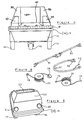
- a wheeled trolley illustrated principally in Figures 1 and 2 of the drawings, comprises a body 11 atop a chassis 12 supported on wheels 13, 14 and 15.
- the wheels 13 and 14 are mounted in one coaxial pair towards the rear of the trolley.
- the single wheel 15 is mounted towards the front of the trolley on the longitudinal centre line of the trolley.
- All the wheels are freely rotatable about their individual axes of rotation.
- the wheel 15 is mounted castor-fashion so that it is freely rotatable about a generally vertical axis when the trolley is in its normally intended attitude of use, standing on the ground, as illustrated in Figures 1 and 2.
- a U-shaped handle 15 is pivoted at 16, 17 respectively to each opposite side wall of the trolley body 11.
- the handle 15 swings freely about its pivots 16, 17 between an in-use position shown in Figures 1 and 2, and a stowed position.
- the handle is swung anti-clockwise (when viewing the trolley as in Figure 1) until it lies flat against the join flange 18 where the chassis 12 abuts the body 11 of the trolley around the trolley periphery.
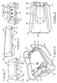
- Figure 3 shows the construction of this join flange 18 whilst Figure 4 shows the handle 15 in its stowed position lying flat on top of the flange 18.
- the body 11 and chassis 12 of the trolley are each moulded from plastics material to form two relatively rigid boxes. They are each peripherally lipped outward to join along, and define, their common flange 18.
- a resilient rubber fender 19 clothes the flange 18 around its entire extent. The fender 19 masks the join as well as protecting the moulded body and chassis of the trolley from sideways impact.
- the coaxial rear wheels 13 and 14 of the trolley are firmly fixed to the underside of the chassis 12.
- the single castor-action front wheel 15 has its castor yoke pivoted to a plate 21 which is itself firmly fixed into a recess moulded into the underside of the chassis 12.
- the body 12 and chassis 11 when joined define a largely open-topped box of considerable carrying capacity.
- the well of the chassis 12 extends virtually uninterrupted along and across the entire area of the trolley.
- the open top 22 of a rear, vertically raised, side wall and end wall portion 23 of the body 11 gives almost unimpeded access to the well of the chassis in that region of the trolley.
- the bulkhead 24 across the trolley which defines the front wall of the raised portion 23 of the body 11, extends down short of the flange 18; and the front portion of the body 11, whilst exhibiting stepped-down walls 25, 26, is again virtually open-topped throughout its entire area.
- Tunnels 27, 28 are moulded into a generally U-shape, from the same plastics material as the chassis 12 is moulded from, and are fixed inboard of the side walls of the combined body-chassis 11, 12 to run along the length of the trolley.
- the tunnels 27 and 28 define, with the inboard regions of the side walls of the body-chassis unit 11, 12, tubular compartments running one along each opposite inboard side of the trolley.
- a sizable but nevertheless relatively readily portable fluid canister 32 sits in the well of the trolley as shown in Figure 2 to protrude slightly from the opening 22.
- the size of the opening 22 relative to the canister 32 is nevertheless such that an appreciable space behind the canister 32 remains, as again Figure 2 illustrates, unoccupied by the canister.
- a ledge 37 is stepped out from the bottom edge of the bulkhead 24 to span the gap between the flat faces 35 and 36 and to join, at each of its opposite ends, a respective one of those two flat faces.
- a similarly sized ledge 38 runs inboard of the body side walls 25 and 26, and across the body between the buttresses 33 and 34, to define a generally U-shaped run of ledge lying in the same plane as the ledge 37.
- Figure 2 shows these details of the ledges 37 and 38. It also shows that, whilst the ledge 38 is continuous around its U-shape, respective cut-outs 39 and 41 are effectively defined in the run of the ledge 38 as it makes the transition from each opposite side run (inboard of a respective one of the walls 25 and 26) to its run across the body between the buttresses 33 and 34.
- a back-pack unit used with the trolley consists essentially of a body 35 atop a chassis 36 each moulded, like the body 11 and chassis 12 of the trolley, from plastics material to encase an electric motor 37, one end of whose output shaft drives a pump 38 whilst the other end presents a square-section drive output 39 externally of the back-pack casing 35, 36.
- the drive motor 37 and pump 38 are proprietary units.
- the motor 37 incorporates reduction gearing whose details need not be specified, between its armature and its drive output 39.
- a fluid entry line 41 and exit supply line 42 run respectfully from positions one on each side of the drive output 39 in the back-pack body 35, inside the body, to and from the pump 38 as illustrated in Figure 8.
- An electrical socket 43 projects from the underside of the back-pack chassis 36 to enable a power supply to the motor 37.
- Padded bearer straps 44, 45 span the underside of the chassis 36 to seat, in use, in the small of the back of a normally proportioned man.
- Adjustable-length straps 46, 47 enable the back-pack to be worn as such in an attitude, illustrated in Figure 12, in which the drive output 39 points vertically downward when the user is standing normally erect.
- the back-pack is so shaped and sized as to sit on the trolley in one mode of use of the apparatus.
- the peripheral region 51 of the underside of the back-pack chassis 36 sits on the ledges 37 and 38 of the trolley body 11; the opposite-side feet 48 and 49 of the back-pack chassis 36 rest on the tops of the tunnels 28 and 27 respectively; and the flat angled surfaces 52 at the front and 53 at the rear of the back-pack body 35 abut the complementary surfaces 54, 55 and 35, 36 respectively of the trolley body 11 to retain the back-pack releaseably on the trolley.
- a sheathed flexible drive known from the existing ROTABRUSH apparatus previously discussed, quick-couples at one end to the motor drive output 39 and at the other end to the input 56 of a tubular handle 57 supporting a brush head 58 in which a cylindrical brush 59 is rotatably journalled.
- the sheathed flexible drive is referenced 61 in Figure 6 from which it will be seen also that the opposite ends of a fluid supply line referenced respectively 62 and 63 protrude from the sheath adjacent the quick-couplings on the respective ends of the drive 61; and these fluid supply line ends themselves carry quick-coupling units of appropriate kind, one to meet with the end 42 of the fluid supply line from the pump 38 of the back-pack unit, the other to couple to an end 64 of a length of fluid supply line 65 running along the handle 57 and into the head 58 of the rotary brush unit.
- the brush 59 of the brush unit is a cylindrical brush whose bristles 66 emerge generally from the longitudinal axis 67 of rotation of the brush.
- the bristles 66 are all substantially the same protruding length so that the envelope of the bristle-ends defines the cylindrical surface of the brush.
- the shaft 68 from which the bristles 66 protrude is perforated, as indicated at 69 in Figure 13, and is tubular.
- the essentially rigid rotary drive shaft 71 which extends up the handle 57 of the brush unit drives the tubular brush core shaft 68 through angled bevel gears 72.
- the fluid supply line 65 enters the brush head 58 and feeds the brush core shaft 68 through a fluid-tight coupling 73 which allows the brush to rotate relative to the non-rotating supply line 65.
- An on-off switch for the motor 37, and a valve to cause cleaning fluid to flow on demand from the pump 38, are mounted on the handle 57 of the brush unit and are linked by appropriately flexible lines to the motor and to the pump respectively. Neither of these user-operated controls is shown in the drawings and their details form no essential feature of the invention embodied in the apparatus illustrated.
- the fluid canister 32 is filled and is stood in the well of the trolley in its Figure 2 illustrated position.
- a reel 74 ( Figure 6) of fluid supply hose is stowed in the well of the trolley in the space behind the canister 32.
- One end 75 of this hose dips below the level of fluid in the canister 32. The other end is quick-coupled to the inlet 41 on the back-pack.
- a reel 77 ( Figure 6) of electrical power supplying cable is also stowed in the trolley behind the canister 32.
- a plug 78 on one end of the cable plugs into the electrical socket 43 on the underside of the back-pack chassis 36.
- Another and appropriately fused and circuit-protected plug 79 on the other end of the electrical supply cable 77 plugs into a mains supply (not shown) socket in the vicinity of the apparatus.
- the flexible drive line 61 is coupled at one end to the back-pack drive output 39 and at its other end to the brush handle drive input 56.
- the fluid supply hose end 63 on the drive line 61 is coupled to the hose end 64 on the brush unit handle 57, and the other end at 62 of the drive line fluid hose is coupled to the fluid output 42 on the back-pack.
- the motor drives the pump to draw fluid from the canister whilst simultaneously driving the flexible drive line to rotate the brush.
- Fluid entering the brush head along the axis of rotation of the brush is spread by centrifugal force to the bristle-ends of the rotating brush and hence to the surface to be cleaned by the brush. It is not necessary for the fluid to be supplied at high pressure by the pump to the brush. Nor is it essential for the fluid to be supplied constantly as the brush rotates.
- the canister 32 is lifted out of the trolley and is transported with the back-pack and the brush unit to the desired location.
- the hose reel 74 and electrical reel 77 leave the trolley with the back-pack unit and travel with that unit to the location. They remain coupled to the back-pack unit in use, as does the drive line 61 and its fluid hose 62, 63.
- the hose 74 dips via its end 75 into the canister 32 as before, and the plug 79 on the end of the electrical cable 77 supplies electrical power to the back-pack unit just as it previously did.
- the cable reel 77 can be unwound as far as is necessary to distance the back-pack unit from the source of electrical supply into which the plug 79 is fitted.
- the canister 32 can either stay close by the back-pack unit or, if feasible, the hose 74 can progressively unwind to accommodate the movement of the back-pack unit from the canister 32 at and around the working location.
- the drive line 61 is not so flexible that it can be coiled into a reel. It is generally U-shaped when not in use. It can therefore be stowed in the well of the trolley, with each of its opposite ends below the back-pack 35 and with its U-section running around the back of the canister 32.
- Spare brush heads, tools, or other equipment can all be stowed in the well of the trolley together with the drive line 61, hose reel 74, electrical cable reel 77 and coiled drive line 61 even though the canister 32 is also in place in the trolley.
- Extension drive line "poles" 81 and 82 which may be supplied with the apparatus, can also be stowed, one in each of the tunnels 27 and 28 running inboard along the trolley side walls.
- the construction and operation of these drive line extension poles is known from the known ROTABRUSH apparatus, as well as being self-evident in the context of this specification. With all these components on board, and with the handle 15 stowed against the trolley join 18, the apparatus is exceptionally compact and unobtrusive yet accommodates everything necessary for both alternative modes of use.
- the brush head shown in Figure 14 is driven in a manner similar to that illustrated in Figures 12 and 13, by bevel gears which in this instance drive through a right-angle.
- Two identical cylindrical brushes each referenced 83 project along a common rotational axis from the brush head.
- Arms 84 support the projecting brushes 83 each of which rotates in the same direction about its common axis 85.
- the brush bristles are splayed so that a substantially continuous bristled envelope contacts the surface to be cleaned.
- the fact that the bristles have to push their way past the top end of the handle 57 in this construction is of less importance than the need to present a continuous bristle envelope to the surface to be cleaned.
- the term "brush” is intended to be functionally definitive in scope. It embodies any implement having a surface-brushing action imparted by a plurality of bristle-equivalent members projecting from the axis about which the "brush” rotates. Thus, for example, a plurality of paddle-like members could project from the axis of the brush head, each having a scraping action on the surface to be cleaned as they rotate.
Landscapes
- Cleaning In General (AREA)
Applications Claiming Priority (2)
| Application Number | Priority Date | Filing Date | Title |
|---|---|---|---|
| GB878708303A GB8708303D0 (en) | 1987-04-07 | 1987-04-07 | Cleaning apparatus |
| GB8708303 | 1987-04-07 |
Publications (1)
| Publication Number | Publication Date |
|---|---|
| EP0309072A1 true EP0309072A1 (en) | 1989-03-29 |
Family
ID=10615397
Family Applications (1)
| Application Number | Title | Priority Date | Filing Date |
|---|---|---|---|
| EP88303059A Withdrawn EP0309072A1 (en) | 1987-04-07 | 1988-04-06 | Cleaning apparatus |
Country Status (5)
| Country | Link |
|---|---|
| US (1) | US4825496A (da) |
| EP (1) | EP0309072A1 (da) |
| CA (1) | CA1300326C (da) |
| DK (1) | DK186088A (da) |
| GB (2) | GB8708303D0 (da) |
Cited By (1)
| Publication number | Priority date | Publication date | Assignee | Title |
|---|---|---|---|---|
| EP0701870A1 (fr) * | 1994-09-15 | 1996-03-20 | Robert Maillet | Dispositif de nettoyage pour mobilier urbain et notamment pour les feux de signalisation de croisement routier |
Families Citing this family (6)
| Publication number | Priority date | Publication date | Assignee | Title |
|---|---|---|---|---|
| US5555597A (en) * | 1994-12-29 | 1996-09-17 | Shop Vac Corporation | Apparatus for converting a vacuum cleaning device into a liquid dispensing and suctioning system |
| US5600866A (en) * | 1995-12-12 | 1997-02-11 | Shop Vac Corporation | Cleaning fluid tank assembly |
| US5780088A (en) * | 1997-01-17 | 1998-07-14 | David R. Zittel | Electric motor driven abrasive roller peeler and cleaning machine |
| DE19913854A1 (de) * | 1998-03-26 | 1999-12-23 | William James Britt | Reinigungsgerät |
| US6523209B1 (en) * | 2001-03-30 | 2003-02-25 | Shari Lynn Dickerson | Wall cleaning apparatus |
| US20060156497A1 (en) * | 2002-08-06 | 2006-07-20 | Burkholder Robert F | Marine and pool cleaner |
Citations (24)
| Publication number | Priority date | Publication date | Assignee | Title |
|---|---|---|---|---|
| US2003847A (en) * | 1932-09-21 | 1935-06-04 | Charles S Woods | Washing device and method |
| US2643732A (en) * | 1951-09-27 | 1953-06-30 | Continental Car Na Var Corp | Vacuum cleaning machine |
| GB905423A (en) * | 1960-07-13 | 1962-09-05 | Osborn Mfg Co | Rotary brush with fluid channels |
| US3138815A (en) * | 1961-08-08 | 1964-06-30 | Jr Lincoln James | Electric window washer improvement |
| GB1062393A (en) * | 1965-02-11 | 1967-03-22 | Joseph Frans Henri Johan Marie | Cleaner for the fire tubes of a boiler |
| GB1074900A (en) * | 1964-06-22 | 1967-07-05 | Flexible Drives Gilmans Ltd | Improvements in or relating to drives for rotary tool cleaning apparatus |
| GB1139037A (en) * | 1966-09-29 | 1969-01-08 | Dendix Brushes Ltd | A rotary brush |
| DE2338081A1 (de) * | 1973-07-25 | 1975-02-06 | Sutter Ag | Bodenreinigungsmaschine |
| FR2265336A1 (en) * | 1974-03-29 | 1975-10-24 | Crego Benedicte | Collector for window cleaning liquid - has reservoir with upper suction device andconnection tube mounting boss |
| DE2539832A1 (de) * | 1975-09-08 | 1977-03-17 | Gerhard Bauer | Sprueh- saug- und trockenreinigungsgeraet zur saeuberung von fussboeden |
| GB1485430A (en) * | 1974-01-14 | 1977-09-14 | Chemtrust Ind Corp | Foam generating apparatus |
| DE2713995A1 (de) * | 1976-03-31 | 1977-10-20 | Reto Huther | Vorrichtung zum reinigen wasserbestaendiger flaechen, insbesondere von fensterscheiben |
| US4068340A (en) * | 1975-06-20 | 1978-01-17 | Steam Vacuum Extraction Limited | Steam and vacuum cleaning apparatus |
| GB2017488A (en) * | 1978-04-03 | 1979-10-10 | Riggers Steeplejacks Ltd | Window cleaning apparatus |
| US4170805A (en) * | 1976-06-21 | 1979-10-16 | Yugen-Gaisha Waikei Giken | Window glass-cleaning device |
| GB2027335A (en) * | 1978-08-12 | 1980-02-20 | Brain R E | Cleaning apparatus |
| US4216563A (en) * | 1979-04-06 | 1980-08-12 | Chemko Industries, Inc. | Combined dry and wet carpet cleaner |
| DE3234088A1 (de) * | 1982-09-14 | 1984-04-12 | Karl-Heinz 8025 Unterhaching Schmiegel | Flaechenreinigungsvorrichtung |
| US4442830A (en) * | 1982-02-24 | 1984-04-17 | Gimelli + Co. Ag | Mouth douche |
| GB2130475A (en) * | 1982-11-23 | 1984-06-06 | Servicemaster Ind | Rotary floor cleaner |
| US4458377A (en) * | 1981-11-12 | 1984-07-10 | Whirlpool Corporation | Wet carpet cleaning apparatus |
| US4531257A (en) * | 1983-11-10 | 1985-07-30 | Ray Passien | Apparatus for cleaning carpet |
| GB2159911A (en) * | 1984-06-07 | 1985-12-11 | British Gas Corp | Pipeline cleaning apparatus |
| FR2572920A1 (fr) * | 1984-11-15 | 1986-05-16 | Ouest Reflet | Appareil pour le nettoyage de toutes surfaces lisses |
Family Cites Families (6)
| Publication number | Priority date | Publication date | Assignee | Title |
|---|---|---|---|---|
| AT97440B (de) * | 1923-06-27 | 1924-07-10 | Egon Reithofer | Vorrichtung zum Abscheren von Mauerflächen. |
| CH109079A (de) * | 1924-06-11 | 1925-02-16 | Bolliger Rudolf | Einrichtung für Kraftbetrieb zum Bürsten von Stalltieren, wie Hornvieh und Pferde. |
| GB420259A (en) * | 1933-12-08 | 1934-11-28 | Hermann Obermuller | Brushing apparatus for painting or the like |
| US2222513A (en) * | 1937-05-07 | 1940-11-19 | James S Mulvaney | Means for cleaning motors |
| US2682067A (en) * | 1949-05-07 | 1954-06-29 | Albert T Coleman | Rotary fountain paintbrush |
| US2918685A (en) * | 1956-09-14 | 1959-12-29 | Harold C Sundstrom | Machine for removing hardened paint |
-
1987
- 1987-04-07 GB GB878708303A patent/GB8708303D0/en active Pending
-
1988
- 1988-04-06 CA CA000563424A patent/CA1300326C/en not_active Expired - Fee Related
- 1988-04-06 DK DK186088A patent/DK186088A/da not_active Application Discontinuation
- 1988-04-06 US US07/178,173 patent/US4825496A/en not_active Expired - Fee Related
- 1988-04-06 GB GB8807985A patent/GB2204375B/en not_active Expired - Fee Related
- 1988-04-06 EP EP88303059A patent/EP0309072A1/en not_active Withdrawn
Patent Citations (24)
| Publication number | Priority date | Publication date | Assignee | Title |
|---|---|---|---|---|
| US2003847A (en) * | 1932-09-21 | 1935-06-04 | Charles S Woods | Washing device and method |
| US2643732A (en) * | 1951-09-27 | 1953-06-30 | Continental Car Na Var Corp | Vacuum cleaning machine |
| GB905423A (en) * | 1960-07-13 | 1962-09-05 | Osborn Mfg Co | Rotary brush with fluid channels |
| US3138815A (en) * | 1961-08-08 | 1964-06-30 | Jr Lincoln James | Electric window washer improvement |
| GB1074900A (en) * | 1964-06-22 | 1967-07-05 | Flexible Drives Gilmans Ltd | Improvements in or relating to drives for rotary tool cleaning apparatus |
| GB1062393A (en) * | 1965-02-11 | 1967-03-22 | Joseph Frans Henri Johan Marie | Cleaner for the fire tubes of a boiler |
| GB1139037A (en) * | 1966-09-29 | 1969-01-08 | Dendix Brushes Ltd | A rotary brush |
| DE2338081A1 (de) * | 1973-07-25 | 1975-02-06 | Sutter Ag | Bodenreinigungsmaschine |
| GB1485430A (en) * | 1974-01-14 | 1977-09-14 | Chemtrust Ind Corp | Foam generating apparatus |
| FR2265336A1 (en) * | 1974-03-29 | 1975-10-24 | Crego Benedicte | Collector for window cleaning liquid - has reservoir with upper suction device andconnection tube mounting boss |
| US4068340A (en) * | 1975-06-20 | 1978-01-17 | Steam Vacuum Extraction Limited | Steam and vacuum cleaning apparatus |
| DE2539832A1 (de) * | 1975-09-08 | 1977-03-17 | Gerhard Bauer | Sprueh- saug- und trockenreinigungsgeraet zur saeuberung von fussboeden |
| DE2713995A1 (de) * | 1976-03-31 | 1977-10-20 | Reto Huther | Vorrichtung zum reinigen wasserbestaendiger flaechen, insbesondere von fensterscheiben |
| US4170805A (en) * | 1976-06-21 | 1979-10-16 | Yugen-Gaisha Waikei Giken | Window glass-cleaning device |
| GB2017488A (en) * | 1978-04-03 | 1979-10-10 | Riggers Steeplejacks Ltd | Window cleaning apparatus |
| GB2027335A (en) * | 1978-08-12 | 1980-02-20 | Brain R E | Cleaning apparatus |
| US4216563A (en) * | 1979-04-06 | 1980-08-12 | Chemko Industries, Inc. | Combined dry and wet carpet cleaner |
| US4458377A (en) * | 1981-11-12 | 1984-07-10 | Whirlpool Corporation | Wet carpet cleaning apparatus |
| US4442830A (en) * | 1982-02-24 | 1984-04-17 | Gimelli + Co. Ag | Mouth douche |
| DE3234088A1 (de) * | 1982-09-14 | 1984-04-12 | Karl-Heinz 8025 Unterhaching Schmiegel | Flaechenreinigungsvorrichtung |
| GB2130475A (en) * | 1982-11-23 | 1984-06-06 | Servicemaster Ind | Rotary floor cleaner |
| US4531257A (en) * | 1983-11-10 | 1985-07-30 | Ray Passien | Apparatus for cleaning carpet |
| GB2159911A (en) * | 1984-06-07 | 1985-12-11 | British Gas Corp | Pipeline cleaning apparatus |
| FR2572920A1 (fr) * | 1984-11-15 | 1986-05-16 | Ouest Reflet | Appareil pour le nettoyage de toutes surfaces lisses |
Cited By (2)
| Publication number | Priority date | Publication date | Assignee | Title |
|---|---|---|---|---|
| EP0701870A1 (fr) * | 1994-09-15 | 1996-03-20 | Robert Maillet | Dispositif de nettoyage pour mobilier urbain et notamment pour les feux de signalisation de croisement routier |
| FR2724585A1 (fr) * | 1994-09-15 | 1996-03-22 | Maillet Robert | Dispositif de nettoyage pour mobilier urbain et notamment pour les feux de signalisation de croisement routier |
Also Published As
| Publication number | Publication date |
|---|---|
| DK186088A (da) | 1988-10-08 |
| DK186088D0 (da) | 1988-04-06 |
| GB2204375B (en) | 1990-10-10 |
| GB8807985D0 (en) | 1988-05-05 |
| GB2204375A (en) | 1988-11-09 |
| US4825496A (en) | 1989-05-02 |
| CA1300326C (en) | 1992-05-12 |
| GB8708303D0 (en) | 1987-05-13 |
Similar Documents
| Publication | Publication Date | Title |
|---|---|---|
| CA2461002C (en) | Surface cleaning apparatus | |
| EP1475029B1 (en) | Surface cleaning apparatus | |
| EP3914137B1 (en) | Floor treatment apparatus | |
| AU2002319444A1 (en) | Surface cleaning apparatus | |
| US4825496A (en) | Cleaning apparatus | |
| CN115349784A (zh) | 表面清洁装置与表面清洁设备 | |
| CN217659635U (zh) | 清洁设备 | |
| CN210995785U (zh) | 一种土壤修复用土壤修复剂喷洒装置 | |
| CN221450541U (zh) | 一种清洁工具 | |
| CN216764353U (zh) | 一种便于移动的水处理剂快速投放装置 | |
| GB2200425A (en) | Back-pack cleaning apparatus | |
| US20250302265A1 (en) | Floor treatment machine | |
| JP3011478U (ja) | スプリンクラー清掃機 | |
| CN117243531A (zh) | 一种清洁工具 | |
| AU2004235647B2 (en) | Surface cleaning apparatus | |
| AU2004201519B2 (en) | Surface cleaning apparatus | |
| ZA200400382B (en) | Surface cleaning apparatus. | |
| JPH1146866A (ja) | 洗浄用ブラシおよびこれを使用した可搬型洗浄装置 |
Legal Events
| Date | Code | Title | Description |
|---|---|---|---|
| PUAI | Public reference made under article 153(3) epc to a published international application that has entered the european phase |
Free format text: ORIGINAL CODE: 0009012 |
|
| AK | Designated contracting states |
Kind code of ref document: A1 Designated state(s): AT BE CH DE ES FR GB GR IT LI LU NL SE |
|
| 17P | Request for examination filed |
Effective date: 19890919 |
|
| 17Q | First examination report despatched |
Effective date: 19910503 |
|
| STAA | Information on the status of an ep patent application or granted ep patent |
Free format text: STATUS: THE APPLICATION IS DEEMED TO BE WITHDRAWN |
|
| 18D | Application deemed to be withdrawn |
Effective date: 19911127 |