EP0309122B1 - Appareil et méthode de test - Google Patents
Appareil et méthode de test Download PDFInfo
- Publication number
- EP0309122B1 EP0309122B1 EP88308319A EP88308319A EP0309122B1 EP 0309122 B1 EP0309122 B1 EP 0309122B1 EP 88308319 A EP88308319 A EP 88308319A EP 88308319 A EP88308319 A EP 88308319A EP 0309122 B1 EP0309122 B1 EP 0309122B1
- Authority
- EP
- European Patent Office
- Prior art keywords
- container
- gas
- liquid
- passageway
- headspace
- Prior art date
- Legal status (The legal status is an assumption and is not a legal conclusion. Google has not performed a legal analysis and makes no representation as to the accuracy of the status listed.)
- Expired - Lifetime
Links
- 238000012360 testing method Methods 0.000 title claims description 16
- 238000000034 method Methods 0.000 title claims description 11
- 239000007789 gas Substances 0.000 claims description 37
- 239000007788 liquid Substances 0.000 claims description 26
- QVGXLLKOCUKJST-UHFFFAOYSA-N atomic oxygen Chemical compound [O] QVGXLLKOCUKJST-UHFFFAOYSA-N 0.000 claims description 12
- 239000001301 oxygen Substances 0.000 claims description 12
- 229910052760 oxygen Inorganic materials 0.000 claims description 12
- 238000004891 communication Methods 0.000 claims description 7
- 235000013361 beverage Nutrition 0.000 description 6
- 238000005259 measurement Methods 0.000 description 5
- 230000000712 assembly Effects 0.000 description 4
- 238000000429 assembly Methods 0.000 description 4
- 210000004027 cell Anatomy 0.000 description 4
- 229910000831 Steel Inorganic materials 0.000 description 3
- 239000010959 steel Substances 0.000 description 3
- IJGRMHOSHXDMSA-UHFFFAOYSA-N Atomic nitrogen Chemical compound N#N IJGRMHOSHXDMSA-UHFFFAOYSA-N 0.000 description 2
- 235000014171 carbonated beverage Nutrition 0.000 description 1
- 210000000170 cell membrane Anatomy 0.000 description 1
- 230000006866 deterioration Effects 0.000 description 1
- 238000006073 displacement reaction Methods 0.000 description 1
- 238000004519 manufacturing process Methods 0.000 description 1
- 238000000465 moulding Methods 0.000 description 1
- 229910052757 nitrogen Inorganic materials 0.000 description 1
- 229920003023 plastic Polymers 0.000 description 1
- 239000004033 plastic Substances 0.000 description 1
- 235000014214 soft drink Nutrition 0.000 description 1
- 239000000126 substance Substances 0.000 description 1
Images


Classifications
-
- G—PHYSICS
- G01—MEASURING; TESTING
- G01M—TESTING STATIC OR DYNAMIC BALANCE OF MACHINES OR STRUCTURES; TESTING OF STRUCTURES OR APPARATUS, NOT OTHERWISE PROVIDED FOR
- G01M3/00—Investigating fluid-tightness of structures
- G01M3/02—Investigating fluid-tightness of structures by using fluid or vacuum
- G01M3/26—Investigating fluid-tightness of structures by using fluid or vacuum by measuring rate of loss or gain of fluid, e.g. by pressure-responsive devices, by flow detectors
- G01M3/32—Investigating fluid-tightness of structures by using fluid or vacuum by measuring rate of loss or gain of fluid, e.g. by pressure-responsive devices, by flow detectors for containers, e.g. radiators
- G01M3/3236—Investigating fluid-tightness of structures by using fluid or vacuum by measuring rate of loss or gain of fluid, e.g. by pressure-responsive devices, by flow detectors for containers, e.g. radiators by monitoring the interior space of the containers
- G01M3/3272—Investigating fluid-tightness of structures by using fluid or vacuum by measuring rate of loss or gain of fluid, e.g. by pressure-responsive devices, by flow detectors for containers, e.g. radiators by monitoring the interior space of the containers for verifying the internal pressure of closed containers
-
- G—PHYSICS
- G01—MEASURING; TESTING
- G01N—INVESTIGATING OR ANALYSING MATERIALS BY DETERMINING THEIR CHEMICAL OR PHYSICAL PROPERTIES
- G01N1/00—Sampling; Preparing specimens for investigation
- G01N1/02—Devices for withdrawing samples
- G01N1/10—Devices for withdrawing samples in the liquid or fluent state
-
- G—PHYSICS
- G01—MEASURING; TESTING
- G01N—INVESTIGATING OR ANALYSING MATERIALS BY DETERMINING THEIR CHEMICAL OR PHYSICAL PROPERTIES
- G01N1/00—Sampling; Preparing specimens for investigation
- G01N1/02—Devices for withdrawing samples
- G01N1/22—Devices for withdrawing samples in the gaseous state
- G01N1/2226—Sampling from a closed space, e.g. food package, head space
-
- G—PHYSICS
- G01—MEASURING; TESTING
- G01N—INVESTIGATING OR ANALYSING MATERIALS BY DETERMINING THEIR CHEMICAL OR PHYSICAL PROPERTIES
- G01N33/00—Investigating or analysing materials by specific methods not covered by groups G01N1/00 - G01N31/00
- G01N33/0078—Testing material properties on manufactured objects
- G01N33/0081—Containers; Packages; Bottles
-
- G—PHYSICS
- G01—MEASURING; TESTING
- G01N—INVESTIGATING OR ANALYSING MATERIALS BY DETERMINING THEIR CHEMICAL OR PHYSICAL PROPERTIES
- G01N1/00—Sampling; Preparing specimens for investigation
- G01N1/02—Devices for withdrawing samples
- G01N1/22—Devices for withdrawing samples in the gaseous state
- G01N1/2226—Sampling from a closed space, e.g. food package, head space
- G01N2001/2229—Headspace sampling, i.e. vapour over liquid
-
- G—PHYSICS
- G01—MEASURING; TESTING
- G01N—INVESTIGATING OR ANALYSING MATERIALS BY DETERMINING THEIR CHEMICAL OR PHYSICAL PROPERTIES
- G01N33/00—Investigating or analysing materials by specific methods not covered by groups G01N1/00 - G01N31/00
- G01N33/02—Food
- G01N33/14—Beverages
Definitions
- the present invention relates to an apparatus and method for testing the contents of a sealed container holding a liquid under the pressure of gas in a headspace.
- the container is typically a can and the liquid may for example be a beverage in which gas is dissolved.
- the can is pierced with a hollow needle having a relatively wide bore.
- the needle communicates with the pressure gauge.
- An inner steel tube is inserted through the needle into the liquid in the can and acts as a siphon for withdrawing a sample of the liquid for a measurement of its dissolved oxygen concentration (see e.g. US-A-3 849 070).
- This arrangement has a disadvantage in that the needle and its associated tubes add appreciably to the volume of the headspace of the can and thus causes inaccuracy in the measurement of the pressure in the headspace.
- an apparatus for testing the contents of a sealed container holding a liquid under the pressure of gas in a headspace including a first piercer positioned and operable to penetrate the top of the container whereby to place the headspace of the container in communication with at least one gas passageway, and a second piercer positioned and operable to penetrate the bottom of the container whereby to place the liquid in communication with the liquid passageway.
- the invention also provides a method for testing the contents of a sealed container holding a liquid under the pressure of gas in a headspace, including piercing the top of the container and passing gas from the headspace through a gas passageway for testing, and then piercing the bottom of the container and passing a liquid from the container through a liquid passageway for testing.
- 'top' and 'bottom' are relative to the position of the container in the apparatus and method according to the invention.
- the invention makes it possible to employ passageways having very small volumes, typically, each under one cubic centimetre, thus making possible relatively accurate measurement of the pressure in the headspace and of the concentration of the chosen dissolved gas, typically oxygen, in the liquid.
- the invention allows for the pre-setting of an accurate counter pressure prior to discharge of the can contents, reducing gas breakout and further improving the accuracy of dissolved gas measurement.
- said at least one gas passageway extends through a body member, and the first piercer comprises a hollow needle having its proximal end mounted in the body and communicating with said gas passageway.
- the gas passageway terminates at one end in one face of the body member and at its other end at an opposite face of the body member.
- a gas passageway at one end receives a pressure gauge and at its other end a pipe having a valve disposed therein enabled to be placed in communication with a source of gas under pressure. This arrangement enables a counter pressure to be applied to the headspace once the gas pressure has been measured therein, which counter pressure can be maintained during the withdrawal of liquid from the bottom of the container so as to reduce the amount of the chosen dissolved gas that comes out of solution during this procedure.
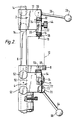
- the can testing apparatus includes an upper can piercing assembly 2 and a lower can piercing assembly 4.
- the assemblies 2 and 4 are mounted on a stand 6.
- the stand 6 also carries a platform 8 on which a can 10 (or other such container), shown in dashed lines in the drawings, is supported.
- the other piercing assembly 2 comprises a block 12 which may be slid up and down the stand and secured in a chosen can piercing position by operation of bolts 14.
- the block 12 guides a body member 16 for vertical movement.
- the body member 16 carries a vertical hollow needle 18 whose proximal end communicates with a gas passageway 20 extending through the body member 16 from one side face 22 to an opposite side face 24 thereof.
- the needle 18 may be lowered so as to pierce the can 10 by lowering (from the position shown in Figure 1 to the position shown in Figures 2 and 3) an arm 26 having an a handle 28 at one end and at its other end being received in a shaft 30 which, as shown in Figures 2 and 3 has eccentrically connected thereto a link 32.
- the link 32 is also connected by a pin 34 to the body member 16.
- the arrangement is such that downward displacement of the arm 26 moves downwards the point of connection between the link 32 and the shaft 30 such that there is corresponding downward movement of the body member 16.
- the needle 18 is formed of steel sufficiently strong to penetrate the top of the can without itself being distorted. As the arm 26 is lowered so an elastomeric bush 38 engaged between the top of the can 10 and the body member 16 is compressed to make a gas-tight seal as the needle 18 penetrates the top of the can 10.
- the end of the passageway 20 terminating in the face 22 receives a pressure gauge 40 whereby pressure in the headspace can be measured.
- a pressure gauge 40 whereby pressure in the headspace can be measured.
- the end of the passageway 20 terminating in the face 24 of the block 12 receives a pipe 42 having a manually operable stop valve 44 located therein at a region near this end.
- the opposite end of the pipe 42 may be connected to a cylinder of gas such as nitrogen (not shown).
- a vent pipe 46 terminates in the pipe 42 at a region intermediate the ends of the pipe 42.
- the vent pipe 46 has a manually operable valve 48 disposed therein. In use, if it is desired to smell the gas in the headspace of the can 10 the valves 44 and 48 may be opened to vent the gas from the headspace.
- the lower piercer assembly 4 is substantially the same as the upper piercer assembly 2 save that it is disposed such that an upward movement rather than a downward movement of the needle causes the bottom of the can to be pierced.
- the piercer assembly 4 includes a block 50 which is able to be slid up and down the stand and can be secured in a chosen position by tightening bolts 52.
- the block 50 guides a body member 54 for vertical movement.
- the body member 54 has the proximal end of a hollow vertically disposed needle 56 disposed therein.
- the proxmial end of the needle 56 communicates with a passageway 58 extending laterally through the body member 54 from one side face 60 to an opposite side face 62 of the body member 54.
- Upward movement of the needle 56 is effected by raising an arm 64 (having a handle 66) from the position shown in Figures 1 and 2 to the position shown in Figure 3.
- the needle 56 extends through a passage 68 in the platform 8 on which the can 10 is seated.
- Raising the arm 64 causes a shaft 70 in which the arm 64 is received to rotate.
- the shaft 70 is eccentrically connected by link 72 to a pin 77 carried by the body member 54.
- the rotation of the shaft 70 caused by raising the arm 64 urges the link 72 upwards and thus moves the needle 56 upwards.
- the needle 56 is made of a steel sufficiently strong to enable it to pierce the bottom of the can 10 without itself being deformed.
- As the arm 64 is raised so as elastomeric bush 69 engaged between the bottom of the can 10 and the body member 54 is compressed to make a seal as the needle 56 pierces the can.
- the end of the passageway 56 that terminates in the face 60 of the block 50 is closed by a manually operable valve 71.
- the other end of the passageway 58 receives the inlet 73 to an electrochemical cell 74, typically of the Clarke type, for measuring dissolved oxygen concentration.
- the cell 74 may form part of a commercial dissolved oxygen meter.
- the cell 74 has an outlet 76 connected by tubing 78 to a drain so that after passing over the face of the cell membrane (not shown) the liquid from the can 10 may be drained away.
- the piercing assemblies 2 and 4 are advantageously assemblies of a kind previously employed for measuring gas pressure.
- they may be Reeve carbonation testers.
- the apparatus shown in the drawings may be made from standard components save for the platform 8 which can readily be formed as a plastics moulding.
- the piercing assemblies 2 and 4 are suitably positioned on the stand 6.
- a can 10 is placed on the platform 8.
- the top of the can 10 is then pierced by lowering the arm 26 to cause the needle 18 to penetrate the top of the can 10 and thus assume the position shown in Figure 2 of the drawings.
- the pressure gauge 40 is thus placed in communication with the headspace of the can and so the pressure in the headspace can be measured.
- Valve 44 is then opened, but valve 48 is kept closed, to permit a gas pressure preferably the same or a little above that recorded by the pressure gauge 40 to be applied to the headspace.
- the arm 64 is then raised to the position shown in Figure 3 cause the needle 56 to penetrate the bottom of the can 10. Liquid is thus caused to flow through the passageway 58 into the cell 74 to enable its dissolved oxygen concentration to be measured using the dissolved oxygen meter (which may for example be of the kind made by Jenway Ltd of Felsted, Essex).
- valve 48 may be momentarily opened.
- the passageways 20 and 58 are typically of very small volume, for example less than 1 cubic centimetre each, to permit relatively accurate measurements of the gas pressure and dissolved oxygen concentration to be made.
- an apparatus according to the invention may be operated with the can supported at an angle of 90° to that shown in the drawings but with the piecers still vertically displaceable.
Landscapes
- Life Sciences & Earth Sciences (AREA)
- Health & Medical Sciences (AREA)
- General Physics & Mathematics (AREA)
- Physics & Mathematics (AREA)
- Chemical & Material Sciences (AREA)
- General Health & Medical Sciences (AREA)
- Analytical Chemistry (AREA)
- Biochemistry (AREA)
- Immunology (AREA)
- Pathology (AREA)
- Engineering & Computer Science (AREA)
- Hydrology & Water Resources (AREA)
- Biomedical Technology (AREA)
- Molecular Biology (AREA)
- Food Science & Technology (AREA)
- Medicinal Chemistry (AREA)
- Sampling And Sample Adjustment (AREA)
- Measuring Fluid Pressure (AREA)
Claims (12)
- Appareil destiné à l'analyse du contenu d'un récipient étanche contenant un liquide placé sous pression par du gaz d'un espace mort, comprenant un premier organe de perçage dont la position et le fonctionnement assurent la pénétration de la partie supérieure du récipient afin que l'espace mort du récipient communique avec au moins un passage de gaz, et un second organe de perçage ayant une position et un fonctionnement tels qu'il peut traverser le fond du récipient afin qu'il mette le liquide en communication avec un passage de liquide.
- Appareil selon la revendication 1, dans lequel le passage de gaz au moins est disposé dans un organe formant un corps et le premier organe de perçage comprend une aiguille creuse dont l'extrémité interne est montée dans le corps et qui communique avec le passage de gaz.
- Appareil selon la revendication 2, dans lequel le passage de gaz aboutit à une première extrémité d'une première face de l'organe formant le corps et, à son autre extrémité, à une face opposée de l'organe formant le corps.
- Appareil selon l'une quelconque des revendications précédentes, dans lequel le passage de gaz placé à une première extrémité comporte un manomètre et, à son autre extrémité, comporte un tube ayant une soupape disposée dans le tube et qui peut communiquer avec une source de gaz sous pression.
- Appareil selon l'une quelconque des revendications précédentes, dans lequel le passage de liquide est formé à travers l'organe du corps, et le second organe de perçage comporte une aiguille creuse dont l'extrémité interne est montée dans le corps et qui communique avec le passage de liquide.
- Appareil selon la revendication 5, dans lequel le passage de liquide communique avec une cellule électro-chimique faisant partie d'un organe de mesure d'oxygène dissous.
- Appareil selon l'une quelconque des revendications précédentes, comprenant en outre une plate-forme sur laquelle peut être placé le récipient, la plate-forme ayant un passage qui la traverse afin que le second organe de perçage puisse être repoussé dans une position dans laquelle il traverse le fond du récipient.
- Appareil selon l'une quelconque des revendications précédentes, dans lequel des passages de gaz et de liquide ont chacun un volume inférieur à 1 cm³.
- Procédé d'analyse du contenu d'un récipient étanche contenant un liquide sous pression d'un gaz d'un espace mort, comprenant le perçage de la partie supérieure du récipient et la transmission du gaz de l'espace mort par un passage de gaz pour l'analyse, puis le perçage du fond du récipient et le passage d'un liquide du récipient dans un passage de liquide pour l'analyse.
- Procédé selon la revendication 9, dans lequel, entre le perçage de la partie supérieure du récipient et le perçage de la partie inférieure du récipient, la pression du gaz de l'espace mort est mesurée et une contre-pression de gaz est appliquée à l'espace mort.
- Procédé selon la revendication 10, dans lequel, après perçage du fond du récipient, un liquide est retiré du passage de liquide et sa concentration en oxygène dissous est mesurée.
- Procédé selon l'une quelconque des revendications 9 à 11, dans lequel le récipient est une boîte.
Applications Claiming Priority (2)
| Application Number | Priority Date | Filing Date | Title |
|---|---|---|---|
| GB8721175 | 1987-09-09 | ||
| GB878721175A GB8721175D0 (en) | 1987-09-09 | 1987-09-09 | Apparatus for testing |
Publications (3)
| Publication Number | Publication Date |
|---|---|
| EP0309122A2 EP0309122A2 (fr) | 1989-03-29 |
| EP0309122A3 EP0309122A3 (en) | 1990-01-31 |
| EP0309122B1 true EP0309122B1 (fr) | 1993-06-23 |
Family
ID=10623495
Family Applications (1)
| Application Number | Title | Priority Date | Filing Date |
|---|---|---|---|
| EP88308319A Expired - Lifetime EP0309122B1 (fr) | 1987-09-09 | 1988-09-08 | Appareil et méthode de test |
Country Status (6)
| Country | Link |
|---|---|
| US (1) | US4926681A (fr) |
| EP (1) | EP0309122B1 (fr) |
| JP (1) | JP2656318B2 (fr) |
| AU (1) | AU2193988A (fr) |
| DE (1) | DE3881995D1 (fr) |
| GB (1) | GB8721175D0 (fr) |
Families Citing this family (15)
| Publication number | Priority date | Publication date | Assignee | Title |
|---|---|---|---|---|
| ATE93623T1 (de) * | 1989-10-09 | 1993-09-15 | Nestle Sa | Verfahren und vorrichtung zur gleichzeitigen bestimmung des sauerstoffgehaltes und des restdruckes in einer verpackung. |
| CH679892A5 (fr) * | 1989-11-17 | 1992-04-30 | Orbisphere Lab | |
| US5220513A (en) * | 1991-02-19 | 1993-06-15 | Seiden Louis W | Gas content measurement in a sealed container of liquid by degassing |
| US5426593A (en) * | 1991-02-19 | 1995-06-20 | Seiden; Louis W. | Gas content measurement |
| US5310658A (en) * | 1992-10-09 | 1994-05-10 | Becton, Dickinson And Company | Method and apparatus for detecting biological activities in a specimen |
| WO1997047729A1 (fr) * | 1996-06-11 | 1997-12-18 | Oxoid Limited | Unite de detection destinee a controler le contenu d'un receptacle contenant un fluide |
| US6205845B1 (en) * | 1999-02-22 | 2001-03-27 | Seagate Technology Llc | Disc drive outgassing system |
| US6393900B1 (en) * | 1999-11-17 | 2002-05-28 | Smithkline Beecham Corporation | Aerosol can content analyzer workstation |
| BR0110729A (pt) * | 2000-10-17 | 2003-06-03 | Ball Corp | Unidade para testar vida de prateleira |
| JP2002131306A (ja) * | 2000-10-25 | 2002-05-09 | Sapporo Breweries Ltd | 飲料製造工程における酸素濃度監視方法及び酸素濃度監視装置 |
| SE0303030D0 (sv) * | 2003-11-14 | 2003-11-14 | Astrazeneca Ab | Canister piercer |
| DE102004054349A1 (de) * | 2004-11-09 | 2006-05-11 | Heuft Systemtechnik Gmbh | Prüfen der Integrität von Produkten in Behältern |
| JP4358785B2 (ja) | 2005-05-27 | 2009-11-04 | 麒麟麦酒株式会社 | 密封容器内の酸素量の測定方法及びこれに用いる密封容器のピアス装置 |
| AT522317B1 (de) * | 2019-04-12 | 2020-10-15 | Anton Paar Gmbh | Verfahren zur Messung des Sauerstoffgehalts des Kopfraumgases in einer Getränkedose |
| AT522387B1 (de) * | 2019-04-12 | 2022-11-15 | Anton Paar Gmbh | Verfahren zur Messung des Sauerstoffgehalts des Kopfraumgases in einem Gebinde |
Family Cites Families (10)
| Publication number | Priority date | Publication date | Assignee | Title |
|---|---|---|---|---|
| US3849070A (en) * | 1972-09-25 | 1974-11-19 | Brewer S Unlimited Inc | Apparatus for and method of determining oxygen and carbon dioxide in sealed containers |
| US3958448A (en) * | 1974-10-10 | 1976-05-25 | Aluminum Company Of America | Test apparatus for pressurized container and method |
| US4089208A (en) * | 1977-01-07 | 1978-05-16 | Owens-Illinois, Inc. | Pressure test fixture for pressurized containers |
| US4152213A (en) * | 1977-03-10 | 1979-05-01 | Johnston Laboratories, Inc. | Vacuum detection of bacteria |
| US4133736A (en) * | 1977-11-22 | 1979-01-09 | Iijima Products M.F.G. Co., Ltd. | Apparatus for determining an oxygen content |
| US4208903A (en) * | 1979-01-19 | 1980-06-24 | The Coca-Cola Company | Automatic carbonation shaker |
| US4281536A (en) * | 1979-09-12 | 1981-08-04 | Kvm Engineering, Inc. | Apparatus for testing the contamination of industrial liquids |
| US4282182A (en) * | 1980-04-20 | 1981-08-04 | Instrumentation Laboratory Inc. | Package sampling system |
| US4555935A (en) * | 1983-10-27 | 1985-12-03 | The Stroh Brewery Company | Apparatus for pressure testing of can bodies and lids |
| US4733555A (en) * | 1987-04-13 | 1988-03-29 | Franks Stephen H | Pressure entry and test system |
-
1987
- 1987-09-09 GB GB878721175A patent/GB8721175D0/en active Pending
-
1988
- 1988-09-07 AU AU21939/88A patent/AU2193988A/en not_active Abandoned
- 1988-09-08 DE DE8888308319T patent/DE3881995D1/de not_active Expired - Lifetime
- 1988-09-08 EP EP88308319A patent/EP0309122B1/fr not_active Expired - Lifetime
- 1988-09-08 US US07/242,017 patent/US4926681A/en not_active Expired - Fee Related
- 1988-09-09 JP JP63226325A patent/JP2656318B2/ja not_active Expired - Lifetime
Also Published As
| Publication number | Publication date |
|---|---|
| EP0309122A2 (fr) | 1989-03-29 |
| AU2193988A (en) | 1989-03-09 |
| DE3881995D1 (de) | 1993-07-29 |
| GB8721175D0 (en) | 1987-10-14 |
| EP0309122A3 (en) | 1990-01-31 |
| JP2656318B2 (ja) | 1997-09-24 |
| US4926681A (en) | 1990-05-22 |
| JPH01113659A (ja) | 1989-05-02 |
Similar Documents
| Publication | Publication Date | Title |
|---|---|---|
| US4926681A (en) | Container content tester | |
| NO171931B (no) | Utstyr og fremgangsmaate for automatisk testing av poroesitet og permeabilitet for flere kjerneproever | |
| US11726009B2 (en) | Method and device for measuring the oxygen content of the headspace gas in a container | |
| US11561154B2 (en) | Method and device for measuring an oxygen content of a headspace gas in a beverage can | |
| US5426593A (en) | Gas content measurement | |
| CN112284629A (zh) | 气密性测试装置及测试方法 | |
| NO313114B1 (no) | Anordning for rengjöring av en nål for å ta pröve av en v¶ske fra en lukket flaske | |
| US4282182A (en) | Package sampling system | |
| US4133736A (en) | Apparatus for determining an oxygen content | |
| US4345458A (en) | Water tank assembly for a pressure resistance measuring apparatus for testing containers | |
| AU2002213242A1 (en) | Shelf life testing unit | |
| US5220513A (en) | Gas content measurement in a sealed container of liquid by degassing | |
| US3942356A (en) | On-line carbon dioxide analyzer and analyzing method | |
| JP3577391B2 (ja) | 陰圧缶ヘッドスペースガス分析方法 | |
| CA1299892C (fr) | Variante de chromatographie en phase gazeuse | |
| CN116793914B (zh) | 岩样骨架体积测定装置和方法 | |
| JP6931945B2 (ja) | 残留気体体積測定装置、残留気体体積測定方法、及び穿刺部材 | |
| CN114858679A (zh) | 一种用于地质学的岩石渗透率测定装置及其使用方法 | |
| CN207049433U (zh) | 一种灌装阀座及用于检测该灌装阀座的检测装置 | |
| CN222671648U (zh) | 物理吸附仪冷却液自动限位及防溢装置 | |
| CN224095337U (zh) | 一种充气包装产品气泡法气密性测试装置 | |
| RU109860U1 (ru) | Устройство для измерения давления со2 в винах, пересыщенных диоксидом углерода | |
| CN223360072U (zh) | 一种新型在线取样阀 | |
| CN111750754B (zh) | 牙轮和金刚石钻头圆周跳动测量及密封性能试验装置 | |
| JPH05163887A (ja) | 孔内水平載荷試験機用の加圧装置 |
Legal Events
| Date | Code | Title | Description |
|---|---|---|---|
| PUAI | Public reference made under article 153(3) epc to a published international application that has entered the european phase |
Free format text: ORIGINAL CODE: 0009012 |
|
| AK | Designated contracting states |
Kind code of ref document: A2 Designated state(s): BE DE FR GB IT NL |
|
| PUAL | Search report despatched |
Free format text: ORIGINAL CODE: 0009013 |
|
| AK | Designated contracting states |
Kind code of ref document: A3 Designated state(s): BE DE FR GB IT NL |
|
| RHK1 | Main classification (correction) |
Ipc: G01N 33/14 |
|
| 17P | Request for examination filed |
Effective date: 19900706 |
|
| 17Q | First examination report despatched |
Effective date: 19920415 |
|
| GRAA | (expected) grant |
Free format text: ORIGINAL CODE: 0009210 |
|
| AK | Designated contracting states |
Kind code of ref document: B1 Designated state(s): BE DE FR GB IT NL |
|
| PG25 | Lapsed in a contracting state [announced via postgrant information from national office to epo] |
Ref country code: BE Effective date: 19930623 Ref country code: NL Effective date: 19930623 Ref country code: FR Effective date: 19930623 Ref country code: DE Effective date: 19930623 Ref country code: IT Free format text: LAPSE BECAUSE OF FAILURE TO SUBMIT A TRANSLATION OF THE DESCRIPTION OR TO PAY THE FEE WITHIN THE PRE;WARNING: LAPSES OF ITALIAN PATENTS WITH EFFECTIVE DATE BEFORE 2007 MAY HAVE OCCURRED AT ANY TIME BEFORE 2007. THE CORRECT EFFECTIVE DATE MAY BE DIFFERENT FROM THE ONE RECORDED.SCRIBED TIME-LIMIT Effective date: 19930623 |
|
| REF | Corresponds to: |
Ref document number: 3881995 Country of ref document: DE Date of ref document: 19930729 |
|
| EN | Fr: translation not filed | ||
| NLV1 | Nl: lapsed or annulled due to failure to fulfill the requirements of art. 29p and 29m of the patents act | ||
| PLBE | No opposition filed within time limit |
Free format text: ORIGINAL CODE: 0009261 |
|
| STAA | Information on the status of an ep patent application or granted ep patent |
Free format text: STATUS: NO OPPOSITION FILED WITHIN TIME LIMIT |
|
| 26N | No opposition filed | ||
| PGFP | Annual fee paid to national office [announced via postgrant information from national office to epo] |
Ref country code: GB Payment date: 19940825 Year of fee payment: 7 |
|
| PG25 | Lapsed in a contracting state [announced via postgrant information from national office to epo] |
Ref country code: GB Effective date: 19950908 |
|
| GBPC | Gb: european patent ceased through non-payment of renewal fee |
Effective date: 19950908 |