EP0309148A2 - Mehrscheiben-Schleifwerkzeug und Herstellungsverfahren - Google Patents
Mehrscheiben-Schleifwerkzeug und Herstellungsverfahren Download PDFInfo
- Publication number
- EP0309148A2 EP0309148A2 EP88308515A EP88308515A EP0309148A2 EP 0309148 A2 EP0309148 A2 EP 0309148A2 EP 88308515 A EP88308515 A EP 88308515A EP 88308515 A EP88308515 A EP 88308515A EP 0309148 A2 EP0309148 A2 EP 0309148A2
- Authority
- EP
- European Patent Office
- Prior art keywords
- depressions
- coating
- cylindrical holder
- longitudinal axis
- mixture
- Prior art date
- Legal status (The legal status is an assumption and is not a legal conclusion. Google has not performed a legal analysis and makes no representation as to the accuracy of the status listed.)
- Granted
Links
Images

Classifications
-
- B—PERFORMING OPERATIONS; TRANSPORTING
- B41—PRINTING; LINING MACHINES; TYPEWRITERS; STAMPS
- B41J—TYPEWRITERS; SELECTIVE PRINTING MECHANISMS, i.e. MECHANISMS PRINTING OTHERWISE THAN FROM A FORME; CORRECTION OF TYPOGRAPHICAL ERRORS
- B41J2/00—Typewriters or selective printing mechanisms characterised by the printing or marking process for which they are designed
- B41J2/005—Typewriters or selective printing mechanisms characterised by the printing or marking process for which they are designed characterised by bringing liquid or particles selectively into contact with a printing material
- B41J2/01—Ink jet
- B41J2/135—Nozzles
- B41J2/16—Production of nozzles
- B41J2/1621—Manufacturing processes
- B41J2/1632—Manufacturing processes machining
- B41J2/1634—Manufacturing processes machining laser machining
-
- B—PERFORMING OPERATIONS; TRANSPORTING
- B23—MACHINE TOOLS; METAL-WORKING NOT OTHERWISE PROVIDED FOR
- B23K—SOLDERING OR UNSOLDERING; WELDING; CLADDING OR PLATING BY SOLDERING OR WELDING; CUTTING BY APPLYING HEAT LOCALLY, e.g. FLAME CUTTING; WORKING BY LASER BEAM
- B23K26/00—Working by laser beam, e.g. welding, cutting or boring
- B23K26/36—Removing material
- B23K26/38—Removing material by boring or cutting
- B23K26/382—Removing material by boring or cutting by boring
- B23K26/384—Removing material by boring or cutting by boring of specially shaped holes
-
- B—PERFORMING OPERATIONS; TRANSPORTING
- B23—MACHINE TOOLS; METAL-WORKING NOT OTHERWISE PROVIDED FOR
- B23K—SOLDERING OR UNSOLDERING; WELDING; CLADDING OR PLATING BY SOLDERING OR WELDING; CUTTING BY APPLYING HEAT LOCALLY, e.g. FLAME CUTTING; WORKING BY LASER BEAM
- B23K26/00—Working by laser beam, e.g. welding, cutting or boring
- B23K26/36—Removing material
- B23K26/40—Removing material taking account of the properties of the material involved
-
- B—PERFORMING OPERATIONS; TRANSPORTING
- B24—GRINDING; POLISHING
- B24D—TOOLS FOR GRINDING, BUFFING OR SHARPENING
- B24D18/00—Manufacture of grinding tools or other grinding devices, e.g. wheels, not otherwise provided for
-
- B—PERFORMING OPERATIONS; TRANSPORTING
- B41—PRINTING; LINING MACHINES; TYPEWRITERS; STAMPS
- B41J—TYPEWRITERS; SELECTIVE PRINTING MECHANISMS, i.e. MECHANISMS PRINTING OTHERWISE THAN FROM A FORME; CORRECTION OF TYPOGRAPHICAL ERRORS
- B41J2/00—Typewriters or selective printing mechanisms characterised by the printing or marking process for which they are designed
- B41J2/005—Typewriters or selective printing mechanisms characterised by the printing or marking process for which they are designed characterised by bringing liquid or particles selectively into contact with a printing material
- B41J2/01—Ink jet
- B41J2/135—Nozzles
- B41J2/16—Production of nozzles
- B41J2/1607—Production of print heads with piezoelectric elements
- B41J2/1609—Production of print heads with piezoelectric elements of finger type, chamber walls consisting integrally of piezoelectric material
-
- B—PERFORMING OPERATIONS; TRANSPORTING
- B41—PRINTING; LINING MACHINES; TYPEWRITERS; STAMPS
- B41J—TYPEWRITERS; SELECTIVE PRINTING MECHANISMS, i.e. MECHANISMS PRINTING OTHERWISE THAN FROM A FORME; CORRECTION OF TYPOGRAPHICAL ERRORS
- B41J2/00—Typewriters or selective printing mechanisms characterised by the printing or marking process for which they are designed
- B41J2/005—Typewriters or selective printing mechanisms characterised by the printing or marking process for which they are designed characterised by bringing liquid or particles selectively into contact with a printing material
- B41J2/01—Ink jet
- B41J2/135—Nozzles
- B41J2/16—Production of nozzles
- B41J2/1621—Manufacturing processes
- B41J2/1632—Manufacturing processes machining
-
- B—PERFORMING OPERATIONS; TRANSPORTING
- B23—MACHINE TOOLS; METAL-WORKING NOT OTHERWISE PROVIDED FOR
- B23K—SOLDERING OR UNSOLDERING; WELDING; CLADDING OR PLATING BY SOLDERING OR WELDING; CUTTING BY APPLYING HEAT LOCALLY, e.g. FLAME CUTTING; WORKING BY LASER BEAM
- B23K2103/00—Materials to be soldered, welded or cut
- B23K2103/30—Organic materials
-
- B—PERFORMING OPERATIONS; TRANSPORTING
- B23—MACHINE TOOLS; METAL-WORKING NOT OTHERWISE PROVIDED FOR
- B23K—SOLDERING OR UNSOLDERING; WELDING; CLADDING OR PLATING BY SOLDERING OR WELDING; CUTTING BY APPLYING HEAT LOCALLY, e.g. FLAME CUTTING; WORKING BY LASER BEAM
- B23K2103/00—Materials to be soldered, welded or cut
- B23K2103/50—Inorganic materials other than metals or composite materials
Definitions
- the present invention relates generally to novel abrasive cutting tools and their method of manufacture and particularly concerns a novel multi-disc cutter, its method of manufacture and its use in the manufacture of ink jet printheads.
- ink jet printheads having a plurality of linear, parallel ink cavities or channels formed in a pre-poled piezoelectric ceramic.
- the dimensions of the ink cavities are quite small and their tolerances must be precisely controlled.
- a typical printhead may, for example, have ink cavities which are about 30-200 microns wide by 150-1000 microns deep and cavity pitch of about 75-500 microns. Due to the linear cutting speeds achievable, the possibility of channel depth profiling and the manufacturing tolerances required, the use of diamond cutting tools is presently preferred to form the ink cavities. While a number of such tools are currently available, their is a need for a more efficient tool, particularly for use in a mass production environment.
- a known prior art technique of forming tools of various configurations is that of laser ablation.
- U.S. Patent 4,533,812 teaches the use of a laser to shape a diamond grinding disc and U.S. Patent 4,170,726 teaches the use of a laser to form a workpiece by melting selected areas of the workpiece and then removing the resulting melt. None of the known prior art techniques, however, is considered satisfactory for the purpose of forming diamond cutting tools suitable for use in the mass production of ink jet printheads, especially printheads having ink cavities with the precisely controlled and extremely fine dimensions described above.
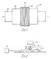
- FIG. 1 A multi-disc cutter 10 manufactured according to the present invention is illustrated in FIG. 1.
- the cutter 10 includes an annular cutting head 12 comprising a plurality of spaced abrasive cutting discs or ridges 14, which may be equally or unequally spaced as desired.
- discs 14 comprise a mixture of diamond powder and resin.
- Annular cutting head 14 is coaxially mounted for rotation on a steel cylinder 16 which, in turn, is coaxially mounted for rotation on a shaft 18.
- Multi-disc cutter 10 is particularly useful in connection with the manufacture of ink jet printheads of the type described in the above-mentioned copending applications.
- These printheads comprise a pre-poled piezoelectric ceramic having a plurality of linear, parallel ink cavities or channels formed therein.
- the cavity dimensions whose tolerances must be very precisely controlled, are typically on the order of 30-200 microns wide by 150-1000 microns deep with a cavity separation pitch of about 75-500 microns.
- the abrasive discs 14 of cutting heads 12 are correspondingly dimensioned and, in particular, preferably have a height H somewhat exceeding the cavity depth, a width W corresponding to the width of the cavities of the printhead and a pitch P equal to or comprising a multiple of the cavity pitch.
- Discs 14 may also be formed with an unequal pitch when required to produce ink channels characterized by an unequal pitch.
- the number of discs 14 on the cutting head 12 is preferably binary to facilitate the cutting of ink cavities in the piezoelectric ceramic to match the electronic drive chips which are normally provided with drive connections that are also binary.
- cutter 10 is used to cut the ink cavities in a sheet of piezoelectric ceramic 11 by mounting the ceramic substrate in a suitable machining jig 13, rotating the cutter by means of shaft 18 at a high speed in the manner of a dicing blade and translating the cutter longitudinally along the length of the ceramic. Rotation and translation of the cutter may be effected by a control system 15. A plurality of linear, parallel cavities are thereby formed in the ceramic. A suitable cutting fluid may, of course, be used to facilitate the cutting process. Alternatively, the piezoelectric ceramic may be longitudinally translated relative to the rotating cutter by a control system 17 to form the cavities.
- the longitudinal translation is preferably performed in a step-wise manner and, depending on the pitch P of discs 14, multiple passes (two to four for example) may be required to cut the cavities to the selected design pitch).
- the cutter discs 14 may be optically inspected from time to time during cutting to maintain precise location of the cutter relative to the piezoelectric ceramic and to identify wear or breakage of cutter discs.
- FIG. 3 A portion of cylinder 16 is initially uniformly coated with a mixture 20 of diamond powder and resin to a depth exceeding the desired height H of discs 14.
- Mixture 20 may comprise an epoxy resin filled with diamond particles having a size of about 0.1-2.0 microns. This composition provides for good bonding of mixture 20 to steel cylinder 16 and also exhibits excellent abrasive characteristics due to the presence of the diamond powder.
- the mixture has a relatively low ablation threshold due to the resin binder. That is, the energy required to ablate the resin is substantially lower than that required for ablation of the diamond powder.
- Shaft 18, mounted in suitable bearings, is coupled to a motor 22 for rotating cylinder 16 and mixture 20 bonded thereto while the coating is exposed to pulsed laser energy of an ultraviolet wavelength.
- the laser energy is supplied by a laser source 24, preferably a pulsed excimer laser, and focused on to the coating 20 by a lens system 26 at an intensity (eg 0.1-0.2 Jcm2 per pulse) suitable for ablating the resin to form an annular depression 28 of selected depth and width circumscribing steel cylinder 16.
- the diamond powder while not being ablated because of its higher ablation threshold (about 10-20 Jcm2 per pulse) will, of course, also be removed since it is held in mixture by the resin.
- the annular depression 28 so formed may extend to the surface of cylinder 16 but, preferably the ablation process is terminated prior to reaching the cylinder surface.
- Conventional pulsed laser sources can conveniently ablate about one micron of the diamond powder-resin mixture per pulse thereby requiring multiple pulse cycles to achieve the desired depth of depression 28.
- the assembly comprising cylinder 16, shaft 18 and mixture 20 is preferably displaced in steps along its longitudinal axis by a positioner 23 so that a plurality of depressions 28 are formed in coating 20.
- lens 26 may be associated with a suitable control mechanism 30 to progressively displace the focused laser beam in equal steps along the longitudinal axis of cylinder 16.
- an annular depression 28 is formed by ablation of the coating so that upon completion of the process, a plurality of such depressions are provided, the depressions being equally spaced along the longitudinal axis of cylinder 16.
- FIG. 4 illustrates another method of forming the cutter 10 illustrated in FIG. 1.
- This method is generally similar to the method shown in FIG. 2 except that a number of depressions 28 are formed simultaneously.
- a suitable mask 32 having a plurality of collimating apertures is flooded with laser energy from a source 34.
- a plurality of collimated laser beams 36 are thereby simultaneously applied to the rotating coating 20.
- Each beam 36 forms a respective annular depression 28 by ablating the resin from the diamond powder-resin mixture to simultaneously create a plurality of equally spaced annular, abrasive cutting discs 14.
- the mask 32 may be configured to form all of the depressions 28 at one time or may be stepped to form the depressions in successive groups.
- an abrasive cutting disc 14 comprising the unablated diamond powder-resin mixture is formed intermediate each successive pair of depressions 28.
- the height H, width W and pitch P of cutting discs 14 may be precisely controlled by appropriately applying selectively focused and stepped laser energy in the formation of depressions 28.
- Laser systems for achieving a high degree of accuracy in forming depressions 28 are well known in the art.
- the discs 14 exhibit a tapered profile, being narrower at the tip and wider at the base of the cutting head.
- the amount of taper shown in the drawing is somewhat exaggerated for purposes of illustration, normally being on the order of about 10 degrees.
- the taper characterizing discs 14 is, of course, the result of the reverse taper exhibited by depressions 28. This reverse taper is an inherent characteristic of the ablation process used in forming cutting head 12.
- the steepness of the walls defining depressions 28 is a function of the energy used in the ablation process, the application of more intense energy resulting in steeper more vertical walls and the application of less energy resulting in walls having a more gradual slope.
- cutting discs 14 of a desired taper can be conveniently provided.
- the channels are normally required to be rectangular.
- the cutting discs 14 In order to cut such rectangular ink channels, the cutting discs 14 must also have a rectangular profile as illustrated in FIG. 5B. This can be effected by introducing a relative rocking motion between the cutter and laser beam during the ablation process. This relative rocking motion tends to undercut the depressions 28 to eliminate the taper that would otherwise be established.
- the cutter assembly can be rocked about its longitudinal axis by positioner 23 while maintaining the laser optics stationary to eliminate the taper or, alternatively, means capable of rocking the optical beam may be provided.
Landscapes
- Engineering & Computer Science (AREA)
- Manufacturing & Machinery (AREA)
- Optics & Photonics (AREA)
- Mechanical Engineering (AREA)
- Physics & Mathematics (AREA)
- Plasma & Fusion (AREA)
- Polishing Bodies And Polishing Tools (AREA)
- Particle Formation And Scattering Control In Inkjet Printers (AREA)
- Magnetic Record Carriers (AREA)
- Application Of Or Painting With Fluid Materials (AREA)
- Laser Beam Processing (AREA)
- Crushing And Pulverization Processes (AREA)
- Control And Other Processes For Unpacking Of Materials (AREA)
- Transition And Organic Metals Composition Catalysts For Addition Polymerization (AREA)
Applications Claiming Priority (2)
| Application Number | Priority Date | Filing Date | Title |
|---|---|---|---|
| GB8722087 | 1987-09-19 | ||
| GB878722087A GB8722087D0 (en) | 1987-09-19 | 1987-09-19 | Multiple cutter |
Publications (3)
| Publication Number | Publication Date |
|---|---|
| EP0309148A2 true EP0309148A2 (de) | 1989-03-29 |
| EP0309148A3 EP0309148A3 (de) | 1991-03-06 |
| EP0309148B1 EP0309148B1 (de) | 1995-09-06 |
Family
ID=10624066
Family Applications (1)
| Application Number | Title | Priority Date | Filing Date |
|---|---|---|---|
| EP88308515A Expired - Lifetime EP0309148B1 (de) | 1987-09-19 | 1988-09-15 | Mehrscheiben-Schleifwerkzeug und Herstellungsverfahren |
Country Status (7)
| Country | Link |
|---|---|
| EP (1) | EP0309148B1 (de) |
| JP (1) | JP2791559B2 (de) |
| AT (1) | ATE127377T1 (de) |
| CA (1) | CA1311129C (de) |
| DE (1) | DE3854415T2 (de) |
| ES (1) | ES2076161T3 (de) |
| GB (1) | GB8722087D0 (de) |
Cited By (5)
| Publication number | Priority date | Publication date | Assignee | Title |
|---|---|---|---|---|
| EP0398571A1 (de) * | 1989-05-17 | 1990-11-22 | Xaar Limited | Mehrscheiben-Schleifwerkzeug und Herstellungsverfahren |
| WO1995011131A1 (en) * | 1993-10-22 | 1995-04-27 | Xaar Limited | Droplet deposition apparatus |
| RU2149750C1 (ru) * | 1999-03-22 | 2000-05-27 | Общество с ограниченной ответственностью "Торговый дом "Абразивные заводы Урала" | Способ формования заготовок абразивного инструмента и устройство для его осуществления |
| US6222157B1 (en) * | 1998-04-17 | 2001-04-24 | L.A. Batchelder And Sons Consulting, Inc. | Seamless holographic transfer using laser generated optical effect patterns |
| JP2015514018A (ja) * | 2012-04-05 | 2015-05-18 | コリア リサーチ インスティチュート オブ スタンダーズ アンド サイエンス | 超高速レーザを用いたホイールの先端部の微小切欠の製造装置および方法 |
Families Citing this family (2)
| Publication number | Priority date | Publication date | Assignee | Title |
|---|---|---|---|---|
| JPH04210381A (ja) * | 1990-11-30 | 1992-07-31 | Osaka Diamond Ind Co Ltd | 研削砥石並びにその製造方法 |
| US5245244A (en) * | 1991-03-19 | 1993-09-14 | Brother Kogyo Kabushiki Kaisha | Piezoelectric ink droplet ejecting device |
Family Cites Families (4)
| Publication number | Priority date | Publication date | Assignee | Title |
|---|---|---|---|---|
| US4151685A (en) * | 1973-05-11 | 1979-05-01 | Frangipane Joseph G | Grinding wheel |
| JPS5469896A (en) * | 1977-11-15 | 1979-06-05 | Koyo Seiko Co Ltd | Method of machining work outer surface with laser beam |
| US4329564A (en) * | 1980-10-28 | 1982-05-11 | Kollmorgen Technologies Corp. | Laser undercutting method |
| DE3202697A1 (de) * | 1982-01-28 | 1983-08-04 | Kapp & Co Werkzeugmaschinenfabrik, 8630 Coburg | Verfahren und vorrichtung zum feinprofilieren von mit superharten werkstoffen beschichteten werkzeugen |
-
1987
- 1987-09-19 GB GB878722087A patent/GB8722087D0/en active Pending
-
1988
- 1988-09-15 EP EP88308515A patent/EP0309148B1/de not_active Expired - Lifetime
- 1988-09-15 DE DE3854415T patent/DE3854415T2/de not_active Expired - Fee Related
- 1988-09-15 ES ES88308515T patent/ES2076161T3/es not_active Expired - Lifetime
- 1988-09-15 AT AT88308515T patent/ATE127377T1/de not_active IP Right Cessation
- 1988-09-19 CA CA000577748A patent/CA1311129C/en not_active Expired - Lifetime
- 1988-09-19 JP JP63232733A patent/JP2791559B2/ja not_active Expired - Fee Related
Cited By (6)
| Publication number | Priority date | Publication date | Assignee | Title |
|---|---|---|---|---|
| EP0398571A1 (de) * | 1989-05-17 | 1990-11-22 | Xaar Limited | Mehrscheiben-Schleifwerkzeug und Herstellungsverfahren |
| WO1995011131A1 (en) * | 1993-10-22 | 1995-04-27 | Xaar Limited | Droplet deposition apparatus |
| US5855713A (en) * | 1993-10-22 | 1999-01-05 | Xaar Technology Limited | Method of making a multi-channel droplet deposition apparatus |
| US6222157B1 (en) * | 1998-04-17 | 2001-04-24 | L.A. Batchelder And Sons Consulting, Inc. | Seamless holographic transfer using laser generated optical effect patterns |
| RU2149750C1 (ru) * | 1999-03-22 | 2000-05-27 | Общество с ограниченной ответственностью "Торговый дом "Абразивные заводы Урала" | Способ формования заготовок абразивного инструмента и устройство для его осуществления |
| JP2015514018A (ja) * | 2012-04-05 | 2015-05-18 | コリア リサーチ インスティチュート オブ スタンダーズ アンド サイエンス | 超高速レーザを用いたホイールの先端部の微小切欠の製造装置および方法 |
Also Published As
| Publication number | Publication date |
|---|---|
| ATE127377T1 (de) | 1995-09-15 |
| EP0309148A3 (de) | 1991-03-06 |
| HK1000051A1 (en) | 1997-10-31 |
| CA1311129C (en) | 1992-12-08 |
| DE3854415T2 (de) | 1996-04-18 |
| DE3854415D1 (de) | 1995-10-12 |
| JP2791559B2 (ja) | 1998-08-27 |
| JPH01140970A (ja) | 1989-06-02 |
| EP0309148B1 (de) | 1995-09-06 |
| GB8722087D0 (en) | 1987-10-28 |
| ES2076161T3 (es) | 1995-11-01 |
Similar Documents
| Publication | Publication Date | Title |
|---|---|---|
| US4929256A (en) | Multi-disc cutter and method of manufacture | |
| US6627844B2 (en) | Method of laser milling | |
| CN106715033B (zh) | 用于在棒形的工件处制造工件面的方法 | |
| EP0488402B1 (de) | Verfahren zum Schneiden von Rillen in ein hydrodynamisches Lager aus keramischem Werkstoff | |
| US5168143A (en) | Method for laser cutting metal plates | |
| EP0309148B1 (de) | Mehrscheiben-Schleifwerkzeug und Herstellungsverfahren | |
| EP0440397B1 (de) | Verfahren zum Laserschneiden von metallischen Platten | |
| EP0830946B1 (de) | Tintenstrahldruckknopf und Verfahren zur Herstellung desselben | |
| HK1000051B (en) | Multi-disc cutter and method of manufacture | |
| EP0398571B1 (de) | Mehrscheiben-Schleifwerkzeug und Herstellungsverfahren | |
| JP2008515643A (ja) | 106〜109Wcm−2の範囲の放射照度と、10〜50kHzの範囲の繰返し率とを有するレーザを使用する硬質材料の加工処理装置及び加工処理方法 | |
| KR20110005006A (ko) | 칩 브레이커가 구비된 다이아몬드 절삭공구의 제조방법 및 이에 의해 제조되는 다이아몬드 절삭공구 | |
| KR20040081878A (ko) | 원추형 피시디 스크라이버 피냇 커터와 그의 커팅홈성형장치 및 성형방법 | |
| EP1287994B1 (de) | Tintenstrahldruckkopf und Herstellungsverfahren | |
| JP2002301581A (ja) | レーザによる溝加工方法及びハニカム構造体成形用金型の製造方法 | |
| Tiffany | Drilling, marking and other applications for industrial Nd: YAG lasers | |
| JP2003145287A (ja) | 硬脆性材料の加工方法 | |
| JPH07304179A (ja) | 流路板及びその製造方法 | |
| JPH1158211A (ja) | 多溝ローラの溝加工方法 | |
| Bergmann et al. | Micromachining with copper vapor lasers | |
| JPS60231588A (ja) | ニユ−セラミツクのレ−ザ−切削加工法 | |
| CN121339697A (zh) | 形成机加工刀具切削刃的方法和机加工设备 | |
| JP2002346956A (ja) | レーザ式け書き針 |
Legal Events
| Date | Code | Title | Description |
|---|---|---|---|
| PUAI | Public reference made under article 153(3) epc to a published international application that has entered the european phase |
Free format text: ORIGINAL CODE: 0009012 |
|
| AK | Designated contracting states |
Kind code of ref document: A2 Designated state(s): AT CH DE ES FR GB GR IT LI NL SE |
|
| PUAL | Search report despatched |
Free format text: ORIGINAL CODE: 0009013 |
|
| 17P | Request for examination filed |
Effective date: 19901220 |
|
| AK | Designated contracting states |
Kind code of ref document: A3 Designated state(s): AT CH DE ES FR GB GR IT LI NL SE |
|
| RAP1 | Party data changed (applicant data changed or rights of an application transferred) |
Owner name: XAAR LIMITED |
|
| 17Q | First examination report despatched |
Effective date: 19920824 |
|
| GRAA | (expected) grant |
Free format text: ORIGINAL CODE: 0009210 |
|
| AK | Designated contracting states |
Kind code of ref document: B1 Designated state(s): AT CH DE ES FR GB GR IT LI NL SE |
|
| PG25 | Lapsed in a contracting state [announced via postgrant information from national office to epo] |
Ref country code: GR Free format text: LAPSE BECAUSE OF FAILURE TO SUBMIT A TRANSLATION OF THE DESCRIPTION OR TO PAY THE FEE WITHIN THE PRESCRIBED TIME-LIMIT Effective date: 19950906 |
|
| REF | Corresponds to: |
Ref document number: 127377 Country of ref document: AT Date of ref document: 19950915 Kind code of ref document: T |
|
| ITF | It: translation for a ep patent filed | ||
| PGFP | Annual fee paid to national office [announced via postgrant information from national office to epo] |
Ref country code: AT Payment date: 19950914 Year of fee payment: 8 |
|
| PGFP | Annual fee paid to national office [announced via postgrant information from national office to epo] |
Ref country code: ES Payment date: 19950928 Year of fee payment: 8 |
|
| REF | Corresponds to: |
Ref document number: 3854415 Country of ref document: DE Date of ref document: 19951012 |
|
| ET | Fr: translation filed | ||
| REG | Reference to a national code |
Ref country code: ES Ref legal event code: FG2A Ref document number: 2076161 Country of ref document: ES Kind code of ref document: T3 |
|
| PLBE | No opposition filed within time limit |
Free format text: ORIGINAL CODE: 0009261 |
|
| STAA | Information on the status of an ep patent application or granted ep patent |
Free format text: STATUS: NO OPPOSITION FILED WITHIN TIME LIMIT |
|
| 26N | No opposition filed | ||
| PG25 | Lapsed in a contracting state [announced via postgrant information from national office to epo] |
Ref country code: AT Effective date: 19960915 |
|
| PG25 | Lapsed in a contracting state [announced via postgrant information from national office to epo] |
Ref country code: ES Free format text: LAPSE BECAUSE OF EXPIRATION OF PROTECTION Effective date: 19960916 |
|
| REG | Reference to a national code |
Ref country code: ES Ref legal event code: FD2A Effective date: 19990601 |
|
| PGFP | Annual fee paid to national office [announced via postgrant information from national office to epo] |
Ref country code: SE Payment date: 20000906 Year of fee payment: 13 |
|
| PGFP | Annual fee paid to national office [announced via postgrant information from national office to epo] |
Ref country code: DE Payment date: 20000911 Year of fee payment: 13 |
|
| PGFP | Annual fee paid to national office [announced via postgrant information from national office to epo] |
Ref country code: FR Payment date: 20000912 Year of fee payment: 13 |
|
| PGFP | Annual fee paid to national office [announced via postgrant information from national office to epo] |
Ref country code: GB Payment date: 20000913 Year of fee payment: 13 |
|
| PGFP | Annual fee paid to national office [announced via postgrant information from national office to epo] |
Ref country code: CH Payment date: 20000922 Year of fee payment: 13 |
|
| PGFP | Annual fee paid to national office [announced via postgrant information from national office to epo] |
Ref country code: NL Payment date: 20000928 Year of fee payment: 13 |
|
| PG25 | Lapsed in a contracting state [announced via postgrant information from national office to epo] |
Ref country code: GB Free format text: LAPSE BECAUSE OF NON-PAYMENT OF DUE FEES Effective date: 20010915 |
|
| PG25 | Lapsed in a contracting state [announced via postgrant information from national office to epo] |
Ref country code: SE Free format text: LAPSE BECAUSE OF NON-PAYMENT OF DUE FEES Effective date: 20010916 |
|
| PG25 | Lapsed in a contracting state [announced via postgrant information from national office to epo] |
Ref country code: LI Free format text: LAPSE BECAUSE OF NON-PAYMENT OF DUE FEES Effective date: 20010930 Ref country code: CH Free format text: LAPSE BECAUSE OF NON-PAYMENT OF DUE FEES Effective date: 20010930 |
|
| REG | Reference to a national code |
Ref country code: GB Ref legal event code: IF02 |
|
| PG25 | Lapsed in a contracting state [announced via postgrant information from national office to epo] |
Ref country code: NL Free format text: LAPSE BECAUSE OF NON-PAYMENT OF DUE FEES Effective date: 20020401 |
|
| PG25 | Lapsed in a contracting state [announced via postgrant information from national office to epo] |
Ref country code: DE Free format text: LAPSE BECAUSE OF NON-PAYMENT OF DUE FEES Effective date: 20020501 |
|
| EUG | Se: european patent has lapsed |
Ref document number: 88308515.1 |
|
| GBPC | Gb: european patent ceased through non-payment of renewal fee |
Effective date: 20010915 |
|
| REG | Reference to a national code |
Ref country code: CH Ref legal event code: PL |
|
| PG25 | Lapsed in a contracting state [announced via postgrant information from national office to epo] |
Ref country code: FR Free format text: LAPSE BECAUSE OF NON-PAYMENT OF DUE FEES Effective date: 20020531 |
|
| NLV4 | Nl: lapsed or anulled due to non-payment of the annual fee |
Effective date: 20020401 |
|
| REG | Reference to a national code |
Ref country code: FR Ref legal event code: ST |
|
| NLV4 | Nl: lapsed or anulled due to non-payment of the annual fee |
Effective date: 20020401 |
|
| PG25 | Lapsed in a contracting state [announced via postgrant information from national office to epo] |
Ref country code: IT Free format text: LAPSE BECAUSE OF NON-PAYMENT OF DUE FEES Effective date: 20050915 |