EP0309192A2 - Steuerung für ein elektronisches Schloss - Google Patents
Steuerung für ein elektronisches Schloss Download PDFInfo
- Publication number
- EP0309192A2 EP0309192A2 EP88308690A EP88308690A EP0309192A2 EP 0309192 A2 EP0309192 A2 EP 0309192A2 EP 88308690 A EP88308690 A EP 88308690A EP 88308690 A EP88308690 A EP 88308690A EP 0309192 A2 EP0309192 A2 EP 0309192A2
- Authority
- EP
- European Patent Office
- Prior art keywords
- locking member
- solenoid
- locking
- drive
- attempt
- Prior art date
- Legal status (The legal status is an assumption and is not a legal conclusion. Google has not performed a legal analysis and makes no representation as to the accuracy of the status listed.)
- Withdrawn
Links
Images


Classifications
-
- E—FIXED CONSTRUCTIONS
- E05—LOCKS; KEYS; WINDOW OR DOOR FITTINGS; SAFES
- E05B—LOCKS; ACCESSORIES THEREFOR; HANDCUFFS
- E05B49/00—Electric permutation locks; Circuits therefor ; Mechanical aspects of electronic locks; Mechanical keys therefor
-
- E—FIXED CONSTRUCTIONS
- E05—LOCKS; KEYS; WINDOW OR DOOR FITTINGS; SAFES
- E05B—LOCKS; ACCESSORIES THEREFOR; HANDCUFFS
- E05B47/00—Operating or controlling locks or other fastening devices by electric or magnetic means
- E05B47/06—Controlling mechanically-operated bolts by electro-magnetically-operated detents
- E05B47/0657—Controlling mechanically-operated bolts by electro-magnetically-operated detents by locking the handle, spindle, follower or the like
- E05B47/0665—Controlling mechanically-operated bolts by electro-magnetically-operated detents by locking the handle, spindle, follower or the like radially
- E05B47/0673—Controlling mechanically-operated bolts by electro-magnetically-operated detents by locking the handle, spindle, follower or the like radially with a rectilinearly moveable blocking element
-
- E—FIXED CONSTRUCTIONS
- E05—LOCKS; KEYS; WINDOW OR DOOR FITTINGS; SAFES
- E05B—LOCKS; ACCESSORIES THEREFOR; HANDCUFFS
- E05B47/00—Operating or controlling locks or other fastening devices by electric or magnetic means
- E05B47/0001—Operating or controlling locks or other fastening devices by electric or magnetic means with electric actuators; Constructional features thereof
- E05B47/0002—Operating or controlling locks or other fastening devices by electric or magnetic means with electric actuators; Constructional features thereof with electromagnets
- E05B2047/0007—Operating or controlling locks or other fastening devices by electric or magnetic means with electric actuators; Constructional features thereof with electromagnets with two or more electromagnets
- E05B2047/0008—Operating or controlling locks or other fastening devices by electric or magnetic means with electric actuators; Constructional features thereof with electromagnets with two or more electromagnets having different functions
-
- E—FIXED CONSTRUCTIONS
- E05—LOCKS; KEYS; WINDOW OR DOOR FITTINGS; SAFES
- E05B—LOCKS; ACCESSORIES THEREFOR; HANDCUFFS
- E05B47/00—Operating or controlling locks or other fastening devices by electric or magnetic means
- E05B2047/0048—Circuits, feeding, monitoring
- E05B2047/0057—Feeding
- E05B2047/0058—Feeding by batteries
-
- E—FIXED CONSTRUCTIONS
- E05—LOCKS; KEYS; WINDOW OR DOOR FITTINGS; SAFES
- E05B—LOCKS; ACCESSORIES THEREFOR; HANDCUFFS
- E05B47/00—Operating or controlling locks or other fastening devices by electric or magnetic means
- E05B2047/0048—Circuits, feeding, monitoring
- E05B2047/0065—Saving energy
-
- E—FIXED CONSTRUCTIONS
- E05—LOCKS; KEYS; WINDOW OR DOOR FITTINGS; SAFES
- E05B—LOCKS; ACCESSORIES THEREFOR; HANDCUFFS
- E05B47/00—Operating or controlling locks or other fastening devices by electric or magnetic means
- E05B47/0001—Operating or controlling locks or other fastening devices by electric or magnetic means with electric actuators; Constructional features thereof
- E05B47/0002—Operating or controlling locks or other fastening devices by electric or magnetic means with electric actuators; Constructional features thereof with electromagnets
- E05B47/0003—Operating or controlling locks or other fastening devices by electric or magnetic means with electric actuators; Constructional features thereof with electromagnets having a movable core
- E05B47/0004—Operating or controlling locks or other fastening devices by electric or magnetic means with electric actuators; Constructional features thereof with electromagnets having a movable core said core being linearly movable
Definitions
- the present invention relates to electronic locking apparatus, in particular to a battery powered door lock operator having a locking plate and solenoid means for driving the locking plate, and a control for the lock operator which maximizes the useful life of the battery.
- Known electronic door locks are battery powered and utilize a single solenoid to provide the locking function.
- Such locks are constructed so that the solenoid is energized for the time that the lock is in the unlocked position. Thus, if the lock remains open for 5-6 seconds, the solenoid draws power and drains the battery for that period of time.
- this type of lock it is almost impossible to provide an alternative function, such as a dormitory function in which the lock will be left open for indefinite periods of time, because such a function would consume batteries at an unacceptable rate.
- U.S. Patent No. 4,132,439 discloses an electronic door lock in which the lock bolt is moved longitudinally by a first solenoid and in which a dead lock element is moved by a second solenoid.
- U.S. Patent No. 4,148,092 describes an electronic door lock with a manually operable deadbolt. This lock features a single solenoid positioned such that its plunger is received by a cavity in the manual turning mechanism thereby preventing the lock from being opened manually.
- U.S. Patent No. 3,893,723 describes an electronically operated door lock in which two solenoids are disposed opposite each other to lock and unlock the door by moving the locking pin into and out of a cavity in the wall.
- U.S. Patent No. 2,224,671 describes an automobile door lock which utilizes a single solenoid instead of a lock spring as a means to prevent opening of the lock.
- U.S. Patent No. 2,765,648 discloses an electronic lock for an automobile in which the lock bolt is actuated by a solenoid and a bar actuated by another solenoid is provided to extend into a notch of the lock bolt to retain the lock bolt in the locked position.
- U.S. Patent No. 3,897,093 discloses an electronic door lock in which two solenoids actuate a pivotally mounted cradle which provides reciprocal movement of the lock bolt.
- the present invention provides an electronic lock apparatus comprising: a locking member movable between a locking position and an unlocking position, a first electromechanical means coupled to the locking member to drive the locking member from one of the positions to the other position upon activation of the first electromechanical means, a second electromechanical means coupled to the locking member to drive the locking member from the one position to the other position upon activation of the second electromechanical means, battery means for powering the first and second electromechanical means, and control means for activating the first electromechanical means without said second electromechanical means to attempt to drive the locking member from the one position to the other position, and for subsequently activating the first and second electromechanical means together to attempt to drive the locking mechanism to the other position.
- the first and second electromechanical means coupled to the locking member comprise first and second solenoids.
- the electronic locking apparatus further comprises voltage sensing means for sensing the voltage of the battery and the control means includes means responsive to the voltage sensing means for activating the first solenoid without the second solenoid to attempt to drive the locking member to the other position when the voltage of the battery means is greater than a predetermined level and activating the first and second solenoids together to attempt to drive the locking member to the other position when the battery voltage is less than the predetermined level.
- the invention also resides in an improvement to an electronic locking apparatus having a lock combination memory containing lock combination data means for reading lock combination data from a key inserted in the electronic locking apparatus, and means for comparing the lock combination data on the key to the lock combination data stored in the lock combination memory.
- the improvement comprises a locking member movable between a locking position and an unlocking position, solenoid means for attempting to drive the locking member from one of the positions to the other position, and control means responsive to a match of the lock combination data on the key and the lock combination data stored in the lock combination memory for activating the solenoid means for a time period to attempt to drive the locking member to the other position, for sensing whether the locking member is in the other position after activation of the solenoid means, and for automatically activating the solenoid means a second time after the time period has elapsed and the solenoid means becomes deactive without reinsertion of the key in the locking apparatus if the solenoid means was unsuccessful in driving the locking member to the other position in the foregoing attempt.
- FIGS 1-3 and 10 illustrate an embodiment of an electronic door lock according to the invention.
- the apparatus comprises an external portion 1 having an external housing 10, an external handle 11, an external operating assembly 20 and an external cover 30, and an internal portion 2 including power source 40, an internal operating assembly 60, and internal housing 70, an internal cover 80 and an internal handle 90.
- Plates 21 and 61 which include the external and internal operating assemblies are attached to housings 10 and 70, respectively, by means of screws, as shown. Screws 100 and 101 hold the lock in place on a door.
- a strike box and strike plate are mounted on the door jamb in a conventional manner.
- a card reader device suitable for use in an electronic door lock according to the present invention is described in co-pending European Patent Application No. [F.14761] of even date.
- a suitable latch bolt assembly for the electronic door lock according to the present invention is described in U.S. Patent No. 4,594,864.
- the external operating assembly 20 comprises a lock cassette body 29, main solenoids 110 and 111 and auxiliary solenoid 112 supported by the lock cassette body, an actuating member 28, a cam plate 27, a rack plate 26, a locking plate 22 which includes two parts, a top plate 24 and a nose piece 25, a pinion 23 and a back plate 21.
- the back plate 21 contains holes 19 through which it may be attached by screws, shown in Figure 1, to tabs 12 and bosses 13 in housing 10.
- the back plate 21 also contains tabs 15 to align the assembly with a standard hole provided in a door.
- the back plate 21 is provided with a boss 119 which extends inwardly and provides a bearing surface for the head 118 of the pinion 23.
- the external operating assembly is attached to the back plate 21 by screws 9 in threaded holes 128 in bosses on the lock cassette body 29. This holds together the entire external operating assembly.
- the housing 10 is provided with a central opening 125 into which a generally square shaped projection 126 of the external lever 11 extends. Tabs 127 are positioned so that the projecting legs of the external cover 30 can rest and maintain the cover in a generally horizontal position for servicing, as show in Figure 1.
- a threaded hole 181 is provided to receive the screw 100 shown in Figure 1.
- the main solenoids 110 (left) and 111 (right) are positioned to engage the ears 127 of the top plate 24 to lift the locking plate vertically between the lower locked and the upper unlocked positions.
- the main solenoids are attached to the lock cassette body 29 by a screw and bracket support 155. Shafts 154 of the main solenoids extend through vertical holes in the support 155.
- the auxiliary solenoid 112 is positioned so that its shaft 150 is perpendicular to the top plate 24 and projects into slots 151 and 152 therein.
- the auxiliary solenoid is attached to the lock cassette body by a screw and generally circular bracket support 157.
- a slot 129 is provided through which the actuator pin 130 of the actuating member 28 fits.
- Vertical sides 140 define a pathway which accommodates the projecting arms 141 of the cam plate 27.
- the body 29 is also provided with an opening 133 through which the projection 126 of the external handle 11 extends. Threaded holes 128 are provided to attach the entire external operating assembly to the plate 21.
- An actuating member 28 is mounted on the internal side of the cassette body 29 with a boss 134 thereof mounted in the opening 133 and the actuator pin 130 fitting through the slot 129.
- the actuator 28 is provided with a generally square shaped opening 135 into which extends the generally square shaped projection 126 of the handle 11.
- the actuator includes a circular shaped base portion 136 and a tail end 137 which supports the actuator pin 130 and a locking pin 138.
- the base portion 136 is provided with a raised V-shaped cam surface 139 which extends inwardly past the plane of the inner surface of tail end 137.
- the cam plate 27 contains projecting arms 141 which fits into the pathway defined by the vertical sides 140 of the lock cassette body 29.
- the cam plate 27 also includes a cam follower surface 142 which engages the V-shaped cam 139 of the actuator 28.
- the cam follower surface 142 is a tab projecting from the cam plate.
- the generally rectangular internal cutout 143 of the cam plate 27 accommodates the rack plate 26.
- the rack plate 26 is mounted within the cutout 143 of the cam plate 27.
- the rack plate 26 has a generally rectangular internal cutout 144 which cutout contains gear teeth 115 on one of the longer, or vertical, sides.
- the gear teeth 115 engage the teeth 114 of the pinion 23.
- the rack 26 has a lip 145 upon its upper portion which serves to hold the rack 26 in place between the cam plate 27 and the top plate 24.
- the position of the locking plate i.e. either locked or unlocked, is not changed. In this manner, the inside door handle can be opened without unlocking the lock.
- the nose piece 25 is attached to the top plate 24 by pressing onto the pin 121 on the top plate 24.
- the nose piece 25 includes a protrusion 146 for engaging the locking pin 138.
- the top plate 24 includes ears 127 which engage the main solenoids 110 and 111 and apertures such as slots 151 and 152 which engage the shaft 150 of the auxiliary solenoid 112.
- An internal cutout 148 is provided to accommodate the rack plate 26 and is sized so that the rack 26 can move vertically without changing the position of the locking plate.
- the pinion member 23 includes gear teeth 114 in mating engagement with the teeth 115 on the rack plate 26. This pinion member 23 extends perpendicularly to the axis of the latch bolt assembly 50.
- the pinion member 23 also includes a tubular extension portion 116 which extends through the top plate 24, rack 26, cam plate 27, actuator 28 and cassette body 29 into an opening 117 in the external handle 11.
- the pinion 23 further includes a head portion 118 which is contained within the boss 119 which extends inwardly on the back plate 21 and provides a bearing surface for the head portion 118.
- the head portion 118 also has a generally rectangular slot 120 therein of mating cross-section with that of spindle 51 which extends therethrough.
- FIG. 3 to 9 shows the locking plate in the lower locked position.
- the locking pin 138 engages the protrusion 146 of the nose piece portion 25 of the locking plate.
- the locking pin 138 is constrained from movement by the protrusion 146 of the nose piece 25 and the wall 153 of the lock cassette body 29.
- the locking pin 138 is attached to the actuating member 28, which in turn engages the lock handle by means of the generally square shaped projection 126 which fits into the aperture 135 of the actuating member 28.
- FIGS 6 and 9 show the locking plate in the upper, unlocked, position.
- the protrusion 146 does not engage the locking pin 138.
- the locking pin 138, the actuating member 28 and the external handle 11 are then free to move. Movement of the external handle 11 will then withdraw the latch bolt.
- This is effected as follows. Turning handle 11 rotates the square shaped projection 126 which rotates the actuator 28, which in turn moves the cam plate 27 in a vertical direction.
- the movement of the cam plate 27 carries with it the rack plate 26. As the rack plate 26 moves upwardly, it causes the pinion 23 to rotate, thus rotating the spindle 51 and withdrawing the latch bolt of the latch mechanism 50.
- the locking plate is moved vertically between the lower and upper positions by energizing one or both of the main solenoids 110 and 111.
- the entire movement can be accomplished in tenths of a second. This is quite significant because the short time of energizing the solenoids minimizes battery draw down.
- the main solenoids 110 and 111 are mounted on lock cassette body 29 by the screw and bracket 155 and positioned to move the locking plate vertically between the lower locked and upper unlocked positions.
- the solenoids 110 and 111 may be of any suitable type such as those manufactured by Ledex, Inc., which produce 0.83 newtons (three ounces of force) at six volts.
- the operation of the main solenoids must be synchronized with the operation of the auxiliary solenoid 112.
- the shaft 150 of the auxiliary solenoid 112 is perpendicular to the locking plate and received in a slot 151 at the top of the locking plate.
- the shaft 150 effectively prevents the locking plate from being moved vertically into the upper position.
- the shaft 150 must be withdrawn immediately prior to the lifting of the locking plate by one or both of the main solenoids 110 and 111.
- Figure 4 shows the shaft 150 of the auxiliary solenoid 112 positioned in the slot 151 of the locking plate and preventing upward movement of the locking plate. In this position, the auxiliary solenoid 112 does not draw any power. After activation, the shaft 150 is withdrawn from the slot 151 and offers no obstruction to the upward movement of the locking plate. This is shown in Figure 5. The locking plate is then moved upward by the action of one or both of the main solenoids 110 and 111 as shown in Figure 7.
- Figure 6 shows the locking plate in the upper unlocked position with both main solenoids energized. The shaft 150 is extended into the slot 152 of the locking plate by means of a spring 180 after the plate has moved past it. This is shown in Figure 8.
- the main and auxiliary solenoids are again activated in a synchronized manner.
- One or both of the main solenoids 110 and 111 are energized and they lift the locking plate over the shaft 150 of the auxiliary solenoid 112.
- the auxiliary solenoid 112 is energized and the shaft 150 is withdrawn. Power is cut to the main solenoids and the locking plate falls to the lower locked position.
- the spring 180 then forces the shaft 150 of the auxiliary solenoid 112 to extend into the slot 151 at the top of the locking plate as discussed previously. The entire operation takes less than one second.
- a presence sensor or microswitch 31 is positioned perpendicular to the locking plate so that it is actuated by movement of the locking plate between the upper and lower positions. The purpose of this microswitch is to determine the status of the lock, locked or unlocked, and transmit the information to the electronic control 3.
- the internal operating assembly is similar to the external operating assembly described above.
- the internal operating assembly includes basically the same lock cassette body, actuating member, cam plate, rack plate and pinion and back plate elements as the external operating assembly. The only significant difference is that there is no locking plate or solenoids associated therewith on the inside to prevent movement of the actuating member. Operation of the internal operating assembly from turning the handle through withdrawing the lock bolt assembly is the same as that of the outside operating mechanism.
- the battery means 40 may comprise any suitable battery, but preferably comprises three, three volt lithium batteries connected in series.
- the batteries are attached to the back plate 61 and supply the electronic control 3, the solenoids 110, 111, and 112, and the card reader 31.
- the electronic control 3 comprises a microprocessor 200, an associated electrically Eraseable Programmable Read Only Memory (EEPROM) 202 which contains an operating program for the microprocessor and one or more lock combinations, a Random Access Memory (RAM) 203 which contains one or more lock combinations, and electronic drivers 204, 206 and 208 which drive the auxiliary or catch solenoid 112, the main solenoid 110 and the main solenoid 111, respectively.
- the electronic drivers are of the MOSFET type, and the microprocessor 200 and RAM 203 may be provided by a microcomputer.
- the electronic control 3 also includes a battery level detector 215 which monitors the voltage of the batteries 40 and by way of example, the battery level detector 215 comprises an analog to digital converter having its input connected to the battery output and an output connected to the microprocessor which reads the battery voltage in digital form.
- a read circuit 205 within the electronic control 3 is connected to the output of the card reader 31 and amplifies the card reader output and converts the output to digital format for reading by the microprocessor 200.
- the battery level detector 215 is used to determine when the battery voltage has fallen below a level required for satisfactory operation of the electronic control 3 and in another embodiment of the invention described below, serves another function as described below.
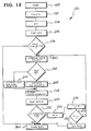
- FIG. 12 One mode of operating the electronic control and the associated solenoids in accordance with the present invention is illustrated in Figure 12 by a flowchart 230, which flowchart includes a computer program or firmware contained within the EEPROM 202.
- a key card When a key card is inserted into the card reader 31, it activates a start switch (not shown), which constitutes a first step 232 of the algorithm 230.
- electronic control 3 is powered up (step 233), and the microprocessor 200 sets a variable N equal to zero (step 234).
- the microprocessor compares one or more lock combinations contained in the data on the key card to one or more lock combinations stored in the RAM 203 or EEPROM 202 to determine whether the key card contains a valid combination suitable to open the lock (step 238). If the key card contains such a valid combination, then the microprocessor 200 activates the electronic driver 204 which in turn drives the auxiliary or catch solenoid 112 and thereby causes it to withdraw from engagement with the locking plate 22 (step 240). Then, the microprocessor 200 determines whether a flag has previously been set (step 242), which flag indicates that in a previous attempt or attempts, a single one of the main solenoids 110 or 111 was unable to lift the locking plate 22. The flag setting will be described in more detail below.
- the microprocessor proceeds to activate one of the main solenoids 110 and 111 for a predetermined time sufficient to raise the locking plate 22 to its upper, unlocked position (step 246), and maintain it there while the microprocessor deactivates the auxiliary or catch solenoid 112 allowing spring 180 to extend shaft 150 of the solenoid into the recess 152 and thereby maintain the locking plate 22 in its upper position (step 248).
- the single main solenoid 110 or 111 need only be activated and auxiliary solenoid 112 deactivated for approximately 0.1 seconds to accomplish both steps 246 and 248.
- the microprocessor 200 reads the presence sensor switch 31 to determine whether the locking plate 22 has in fact been lifted to its unlocking position and held by the auxiliary solenoid 112 (steps 250 and 252). If the lifting of the locking plate 22 has been successfully completed, then the locking apparatus 8 is unlocked and the microprocessor 200 will power down (step 214) and the user will be able to open the door by rotating the door handle. However, the locking plate 22 may not have been lifted and maintained in its upper locking position for the following reasons. After prolonged use of the locking apparatus 8, the battery voltage may have fallen to a level at which the single main solenoid 110 or 111 is driven with inadequate power to develop the force necessary to lift the locking plate 22.
- the microprocessor proceeds to the step 254 in which it waits a predetermined time before again attempting to lift the locking plate 22.
- the predetermined time is in the interval 1-4 seconds.
- the microprocessor increments the variable N (step 256) and then determines whether the variable N is less than four (step 258). This sets a limit to the total number of attempts at lifting the locking plate 22 before powering down. If the variable N is less than four, the microprocessor proceeds back to the steps 240, 242, 246, 248 and 250 to again attempt to lift the locking plate 24 with one of the main solenoids 110 or 111 and maintain it in its upper position.
- This loop may be repeated two additional times until the variable N equals 4 at which time, the microprocessor 200 sets the flat (260) referenced above in the step 242 to indicate the inability of the single main solenoid 110 or 111 to lift the locking plate 22. then, the microprocessor 200 powers down (262).
- step 234 the microprocessor activates both of the main solenoids 110 and 111 to attempt to lift the locking plate.
- the power delivered to each solenoid corresponds to the force that each solenoid develops so that two solenoids provide twice the force as compared to one at a given voltage.
- both of the main solenoids 110 and 111 under the condition in which the battery voltage is insufficient to drive the single solenoid substantially prolongs the useful life of the batteries.
- the batteries will sustain a voltage under load which is sufficient to drive the two solenoids 110 and 111 together for substantially longer than they are able to sustain a voltage under load sufficient to drive a single main solenoid 110 or 111.
- the useful life of the battery is extended by approximately forty percent. It should also be noted that if both the main solenoids 110 and 111 were always utilized to lift the locking plate 22, when the batteries are fresh approximately twice the power of the batteries would be consumed in lifting the locking plate 22 than is needed, thus accelerating the drainage of the batteries.
- the microprocessor proceeds to deactivate the auxiliary or catch solenoid 112 so that it extends under the force of its spring bias into the recess 152 and thereby maintains the locking plate 22 in its upper position if in fact the solenoid plate has been lifted.
- the microprocessor 200 then reads the presence sensing switch 31 to determine if the locking plate has been successfully lifted (steps 250 and 252), and, if not, attempts to lift the locking plate with the two solenoids 110 and 111, one, two or three more times after predetermined intervals according to the steps 254, 256, 258, 240, 242, 244, 248 and 250. After a successful lift or three unsuccessful attempts, the microprocessor powers down (step 264).
- step 238 if a key card having an invalid lock combination is inserted into the lock, this fact is noted in the step 238 and the microprocessor does not attempt to activate the solenoid(s) and jumps to the step 264 in which it powers down.
- the microprocessor after the microprocessor performs the step 260 in which it sets the flag, the microprocessor jumps to the step 240 and then steps 242 and 244 to attempt immediately to lift the locking plate by activating both of the main solenoids 110 and 111 simultaneously.
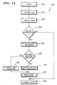
- a further embodiment of the invention is shown by flowchart 300 which utilizes the electronic control 3 but with a different computer program stored in the EEPROM 202.
- insertion of the key card activates the power switch to power up the electronic control (steps 302 and 304) and initiates the reading of the data on the card (step 306) to determine whether the key card contains a valid lock combination (step 308). If the key card contains a valid combination, the microprocessor activates the auxiliary or catch solenoid 112 to withdraw it from the recess 151. The microprocessor then reads the output of the battery level detector 215 to determine whether the battery provides sufficient voltage to drive a single one of the main solenoids 110 or 111 (step 312).
- the microprocessor activates one of the main solenoids 110 or 111 (step 316) and then deactivates the auxiliary or catch solenoid 112 (318) so that the auxiliary solenoid will extend into the recess 152 if the locking plate 22 has in fact been lifted. If, on the other hand, the microprocessor reads a battery voltage in the step 312 which is less than a predetermined level capable of driving one of the main solenoids, the microprocessor proceeds to activate both of the main solenoids 110 and 111 (step 314) and then deactivates the auxiliary or catch solenoid 112 (step 318). In this embodiment of the invention, after the step 318, the microprocessor proceeds to power down irrespective of whether the locking plate 22 has been lifted. In a variation to the flowchart 300, after the step 318, the microprocessor may be programmed to repeat the attempt to lift the locking plate in the manner illustrated by the steps 254, 256 illustrated in Figure 12.
Landscapes
- Lock And Its Accessories (AREA)
Applications Claiming Priority (2)
| Application Number | Priority Date | Filing Date | Title |
|---|---|---|---|
| US9992187A | 1987-09-23 | 1987-09-23 | |
| US99921 | 1987-09-23 |
Publications (2)
| Publication Number | Publication Date |
|---|---|
| EP0309192A2 true EP0309192A2 (de) | 1989-03-29 |
| EP0309192A3 EP0309192A3 (de) | 1990-02-28 |
Family
ID=22277251
Family Applications (1)
| Application Number | Title | Priority Date | Filing Date |
|---|---|---|---|
| EP88308690A Withdrawn EP0309192A3 (de) | 1987-09-23 | 1988-09-20 | Steuerung für ein elektronisches Schloss |
Country Status (6)
| Country | Link |
|---|---|
| EP (1) | EP0309192A3 (de) |
| JP (1) | JPH01198979A (de) |
| KR (1) | KR890005366A (de) |
| CN (1) | CN1032565A (de) |
| AU (1) | AU2247488A (de) |
| IL (1) | IL87750A0 (de) |
Cited By (1)
| Publication number | Priority date | Publication date | Assignee | Title |
|---|---|---|---|---|
| RU2191877C2 (ru) * | 2000-06-22 | 2002-10-27 | Сергей Александрович Фивейский | Электромеханический замок |
Families Citing this family (2)
| Publication number | Priority date | Publication date | Assignee | Title |
|---|---|---|---|---|
| US8640513B2 (en) * | 2011-06-22 | 2014-02-04 | The Stanley Works Israel Ltd. | Electronic and manual lock assembly |
| NZ629856A (en) | 2012-01-30 | 2016-09-30 | Schlage Lock Co Llc | Lock devices, systems and methods |
-
1988
- 1988-09-15 IL IL87750A patent/IL87750A0/xx unknown
- 1988-09-20 EP EP88308690A patent/EP0309192A3/de not_active Withdrawn
- 1988-09-21 AU AU22474/88A patent/AU2247488A/en not_active Abandoned
- 1988-09-22 JP JP63238675A patent/JPH01198979A/ja active Pending
- 1988-09-22 KR KR1019880012244A patent/KR890005366A/ko not_active Withdrawn
- 1988-09-24 CN CN88106858A patent/CN1032565A/zh active Pending
Non-Patent Citations (1)
| Title |
|---|
| No further relevant document have been disclosed * |
Cited By (1)
| Publication number | Priority date | Publication date | Assignee | Title |
|---|---|---|---|---|
| RU2191877C2 (ru) * | 2000-06-22 | 2002-10-27 | Сергей Александрович Фивейский | Электромеханический замок |
Also Published As
| Publication number | Publication date |
|---|---|
| KR890005366A (ko) | 1989-05-13 |
| IL87750A0 (en) | 1989-02-28 |
| AU2247488A (en) | 1989-03-23 |
| EP0309192A3 (de) | 1990-02-28 |
| JPH01198979A (ja) | 1989-08-10 |
| CN1032565A (zh) | 1989-04-26 |
Similar Documents
| Publication | Publication Date | Title |
|---|---|---|
| US4843851A (en) | Locking mechanism for multifunctional electronic lock | |
| EP1264060B1 (de) | Elektronisches schloss | |
| US6185773B1 (en) | Remote control mechanism for a locker | |
| US4901545A (en) | Self-contained electromechanical locking device | |
| US4656850A (en) | Electric lock | |
| US4936122A (en) | Electronic door lock assembly | |
| EP0498465B1 (de) | Durch magnetischen Schlüssel betätigbares Schloss und Modul dafür | |
| CA2383527A1 (en) | Medical cart with electronically lockable pharmaceutical and narcotic drawers | |
| EP0312123A1 (de) | Sicherheitsanordnung, insbesondere elektrisch betätigtes Schloss | |
| EP0373232A1 (de) | Motorgetriebenes Schloss mit Steuerung | |
| EP1710753A2 (de) | Türschloss mit RFID-Schlüssel | |
| US5010751A (en) | Safe device and mechanism for operating the same | |
| US4887442A (en) | Electronic lockset assembly and control | |
| US20050284200A1 (en) | Electronic lock | |
| WO1998015703A1 (en) | Electro-mechanical lock | |
| US20240191546A1 (en) | Door-strike | |
| US5678868A (en) | Electronic door locking mechanism | |
| EP0309192A2 (de) | Steuerung für ein elektronisches Schloss | |
| US5094093A (en) | Electronic lock | |
| WO1999014457A1 (en) | A door lock system | |
| EP1617020A2 (de) | Elektronisches Schloss | |
| JP5069694B2 (ja) | 電気機械的回転ロックシリンダ | |
| KR100535243B1 (ko) | 도어 잠금장치 | |
| GB2281938A (en) | Auxiliary retrofit lock system for mortise lock | |
| JP2944252B2 (ja) | 冷蔵庫装置 |
Legal Events
| Date | Code | Title | Description |
|---|---|---|---|
| PUAI | Public reference made under article 153(3) epc to a published international application that has entered the european phase |
Free format text: ORIGINAL CODE: 0009012 |
|
| AK | Designated contracting states |
Kind code of ref document: A2 Designated state(s): BE CH DE ES FR GB IT LI NL |
|
| PUAL | Search report despatched |
Free format text: ORIGINAL CODE: 0009013 |
|
| AK | Designated contracting states |
Kind code of ref document: A3 Designated state(s): BE CH DE ES FR GB IT LI NL |
|
| RAP1 | Party data changed (applicant data changed or rights of an application transferred) |
Owner name: EMHART INDUSTRIES, INC. |
|
| STAA | Information on the status of an ep patent application or granted ep patent |
Free format text: STATUS: THE APPLICATION IS DEEMED TO BE WITHDRAWN |
|
| 18D | Application deemed to be withdrawn |
Effective date: 19900829 |