EP0309316A1 - Procédé pour la fabrication d'un volant de direction allégé - Google Patents
Procédé pour la fabrication d'un volant de direction allégé Download PDFInfo
- Publication number
- EP0309316A1 EP0309316A1 EP88402313A EP88402313A EP0309316A1 EP 0309316 A1 EP0309316 A1 EP 0309316A1 EP 88402313 A EP88402313 A EP 88402313A EP 88402313 A EP88402313 A EP 88402313A EP 0309316 A1 EP0309316 A1 EP 0309316A1
- Authority
- EP
- European Patent Office
- Prior art keywords
- steering wheel
- fibers
- blanks
- synthetic material
- rim
- Prior art date
- Legal status (The legal status is an assumption and is not a legal conclusion. Google has not performed a legal analysis and makes no representation as to the accuracy of the status listed.)
- Granted
Links
- 238000000034 method Methods 0.000 title claims description 18
- 238000004519 manufacturing process Methods 0.000 title claims description 8
- 239000000835 fiber Substances 0.000 claims abstract description 32
- 229920002994 synthetic fiber Polymers 0.000 claims abstract description 27
- 230000002093 peripheral effect Effects 0.000 claims description 5
- 239000011159 matrix material Substances 0.000 claims description 4
- 229920001187 thermosetting polymer Polymers 0.000 claims description 4
- 229920000914 Metallic fiber Polymers 0.000 claims description 3
- 239000000463 material Substances 0.000 claims description 3
- 229920001169 thermoplastic Polymers 0.000 claims description 3
- 239000004416 thermosoftening plastic Substances 0.000 claims description 3
- 229910052500 inorganic mineral Inorganic materials 0.000 claims 2
- 239000011707 mineral Substances 0.000 claims 2
- 239000012815 thermoplastic material Substances 0.000 claims 1
- 239000002184 metal Substances 0.000 description 8
- 239000000047 product Substances 0.000 description 6
- 239000004033 plastic Substances 0.000 description 5
- 229920003023 plastic Polymers 0.000 description 5
- 239000006096 absorbing agent Substances 0.000 description 4
- 239000011248 coating agent Substances 0.000 description 3
- 238000000576 coating method Methods 0.000 description 3
- 230000002787 reinforcement Effects 0.000 description 3
- 206010052428 Wound Diseases 0.000 description 2
- 208000027418 Wounds and injury Diseases 0.000 description 2
- 239000002131 composite material Substances 0.000 description 2
- 238000001125 extrusion Methods 0.000 description 2
- 238000000465 moulding Methods 0.000 description 2
- 239000011265 semifinished product Substances 0.000 description 2
- 239000000243 solution Substances 0.000 description 2
- OKTJSMMVPCPJKN-UHFFFAOYSA-N Carbon Chemical compound [C] OKTJSMMVPCPJKN-UHFFFAOYSA-N 0.000 description 1
- 208000034656 Contusions Diseases 0.000 description 1
- 229920002430 Fibre-reinforced plastic Polymers 0.000 description 1
- 229920000271 Kevlar® Polymers 0.000 description 1
- 239000004952 Polyamide Substances 0.000 description 1
- 239000004743 Polypropylene Substances 0.000 description 1
- 229920005830 Polyurethane Foam Polymers 0.000 description 1
- 239000011230 binding agent Substances 0.000 description 1
- 229910052799 carbon Inorganic materials 0.000 description 1
- 238000003776 cleavage reaction Methods 0.000 description 1
- 239000000470 constituent Substances 0.000 description 1
- 230000006378 damage Effects 0.000 description 1
- 208000037265 diseases, disorders, signs and symptoms Diseases 0.000 description 1
- 230000007717 exclusion Effects 0.000 description 1
- 239000011151 fibre-reinforced plastic Substances 0.000 description 1
- 239000000945 filler Substances 0.000 description 1
- 235000021189 garnishes Nutrition 0.000 description 1
- 239000011521 glass Substances 0.000 description 1
- 238000001746 injection moulding Methods 0.000 description 1
- 208000014674 injury Diseases 0.000 description 1
- 239000004761 kevlar Substances 0.000 description 1
- 239000010985 leather Substances 0.000 description 1
- 239000002557 mineral fiber Substances 0.000 description 1
- 229920002647 polyamide Polymers 0.000 description 1
- -1 polypropylene Polymers 0.000 description 1
- 229920001155 polypropylene Polymers 0.000 description 1
- 239000011496 polyurethane foam Substances 0.000 description 1
- 238000003303 reheating Methods 0.000 description 1
- 239000011347 resin Substances 0.000 description 1
- 229920005989 resin Polymers 0.000 description 1
- 238000000518 rheometry Methods 0.000 description 1
- 230000007017 scission Effects 0.000 description 1
- 230000035939 shock Effects 0.000 description 1
Images

Classifications
-
- B—PERFORMING OPERATIONS; TRANSPORTING
- B62—LAND VEHICLES FOR TRAVELLING OTHERWISE THAN ON RAILS
- B62D—MOTOR VEHICLES; TRAILERS
- B62D1/00—Steering controls, i.e. means for initiating a change of direction of the vehicle
-
- B—PERFORMING OPERATIONS; TRANSPORTING
- B62—LAND VEHICLES FOR TRAVELLING OTHERWISE THAN ON RAILS
- B62D—MOTOR VEHICLES; TRAILERS
- B62D1/00—Steering controls, i.e. means for initiating a change of direction of the vehicle
- B62D1/02—Steering controls, i.e. means for initiating a change of direction of the vehicle vehicle-mounted
- B62D1/04—Hand wheels
-
- B—PERFORMING OPERATIONS; TRANSPORTING
- B29—WORKING OF PLASTICS; WORKING OF SUBSTANCES IN A PLASTIC STATE IN GENERAL
- B29C—SHAPING OR JOINING OF PLASTICS; SHAPING OF MATERIAL IN A PLASTIC STATE, NOT OTHERWISE PROVIDED FOR; AFTER-TREATMENT OF THE SHAPED PRODUCTS, e.g. REPAIRING
- B29C70/00—Shaping composites, i.e. plastics material comprising reinforcements, fillers or preformed parts, e.g. inserts
- B29C70/04—Shaping composites, i.e. plastics material comprising reinforcements, fillers or preformed parts, e.g. inserts comprising reinforcements only, e.g. self-reinforcing plastics
- B29C70/28—Shaping operations therefor
- B29C70/30—Shaping by lay-up, i.e. applying fibres, tape or broadsheet on a mould, former or core; Shaping by spray-up, i.e. spraying of fibres on a mould, former or core
- B29C70/34—Shaping by lay-up, i.e. applying fibres, tape or broadsheet on a mould, former or core; Shaping by spray-up, i.e. spraying of fibres on a mould, former or core and shaping or impregnating by compression, i.e. combined with compressing after the lay-up operation
- B29C70/345—Shaping by lay-up, i.e. applying fibres, tape or broadsheet on a mould, former or core; Shaping by spray-up, i.e. spraying of fibres on a mould, former or core and shaping or impregnating by compression, i.e. combined with compressing after the lay-up operation using matched moulds
-
- B—PERFORMING OPERATIONS; TRANSPORTING
- B29—WORKING OF PLASTICS; WORKING OF SUBSTANCES IN A PLASTIC STATE IN GENERAL
- B29C—SHAPING OR JOINING OF PLASTICS; SHAPING OF MATERIAL IN A PLASTIC STATE, NOT OTHERWISE PROVIDED FOR; AFTER-TREATMENT OF THE SHAPED PRODUCTS, e.g. REPAIRING
- B29C70/00—Shaping composites, i.e. plastics material comprising reinforcements, fillers or preformed parts, e.g. inserts
- B29C70/68—Shaping composites, i.e. plastics material comprising reinforcements, fillers or preformed parts, e.g. inserts by incorporating or moulding on preformed parts, e.g. inserts or layers, e.g. foam blocks
- B29C70/86—Incorporated in coherent impregnated reinforcing layers, e.g. by winding
-
- Y—GENERAL TAGGING OF NEW TECHNOLOGICAL DEVELOPMENTS; GENERAL TAGGING OF CROSS-SECTIONAL TECHNOLOGIES SPANNING OVER SEVERAL SECTIONS OF THE IPC; TECHNICAL SUBJECTS COVERED BY FORMER USPC CROSS-REFERENCE ART COLLECTIONS [XRACs] AND DIGESTS
- Y10—TECHNICAL SUBJECTS COVERED BY FORMER USPC
- Y10T—TECHNICAL SUBJECTS COVERED BY FORMER US CLASSIFICATION
- Y10T74/00—Machine element or mechanism
- Y10T74/20—Control lever and linkage systems
- Y10T74/20576—Elements
- Y10T74/20732—Handles
- Y10T74/20834—Hand wheels
Definitions
- the invention relates to steering wheels in particular for motor vehicles and, more particularly, relates to a lightened steering wheel in particular for this type of use obtained from a reinforced stampable synthetic material and a method for the manufacture of such a steering wheel.
- the steering wheel must be relatively light in order to have a reduced mass and a small moment of inertia with respect to the axis of the steering column for reasons notably of comfort.
- the small mass means that when the vehicle is traveling at high speed or on poor track conditions, the steering wheel does not vibrate.
- the small moment of inertia facilitates steering turns and changes of direction when the vehicle is in use.
- the steering wheel must be able to withstand significant deformations resulting from efforts in the event of a violent impact, particularly from the front.
- the driver's chest comes into contact with the steering wheel, it must not cause bruising injuries or cause cuts or puncture wounds.
- a flywheel essentially comprises a central hub and a peripheral rim which are connected to each other by at least one arm or an approximately radial branch.
- flywheels in addition to the hub which is generally made of metal include other metallic components.
- the current trend consists in using such a metallic hub and in associating it with rims and branches with metal reinforcements or reinforcements in order to satisfy both mechanical and safety constraints.
- a metal hub is used which is associated with arms and a rim obtained by a double injection molding technique during which the outer part is first made of plastic which serves as an envelope into which is then injected another charged plastic manner which serves as a core.
- the object of the invention is to manufacture a lightened steering wheel, in particular for a motor vehicle, the only metal part of which is its hub in order to satisfy all the usual constraints.
- the term “flywheel” designates the internal part of the latter which has a “mechanical” role, to the exclusion of any subsequent external coating which gives it its final appearance which is pleasant to see and to touch.
- a semi-finished product which consists of a synthetic material and fibers, the relative percentage by mass of which is very high compared to the synthetic material which coats them so that they can be easily handled as is. blank form.
- This semi-product is used after possible reheating of the blanks to garnish a mold made of a punch and a matrix with an imprint of the object to be obtained so as to compress it there with an energy and a speed which allow it to conform by stamping without breaking the long or continuous constituent fibers.
- multiple blanks of semi-finished product of the same nature or not are used so as to obtain an orientation and a density of the fibers which satisfy the mechanical and safety constraints.
- the only metal part is the hub.
- the subject of the invention is a lightened steering wheel in particular for a motor vehicle consisting, inter alia, of a central hub, of a peripheral rim, and of at least one approximately radial branch or arm connecting hub and rim.
- this steering wheel is remarkable in that at least rim and branch are made of blanks of a semi-product of at least one synthetic material loaded with long stampable fibers.
- the invention also relates to a method of manufacturing a lightened steering wheel, in particular for a motor vehicle of the type indicated above using a mold having a punch and a die in which an imprint of the steering wheel to be obtained is formed.
- the imprint of blanks is at least partially filled with at least half a product made of a synthetic material loaded with fibers and these blanks are shaped by stamping.
- Synthetic materials loaded with single-filament or multi-strand fibers, twisted or not and possibly assembled in strands, which are oriented or woven, are well known.
- thermosetting plastics or prepreg thermoplastics of this type There are thermosetting plastics or prepreg thermoplastics of this type. However, it is difficult to use them according to the prior art to obtain steering wheels which are satisfactory. In particular, it is then necessary to use plastics which are very resistant and which are often expensive because they are very specific, or else they must be used in very large quantities, which only increases the price, the mass and the timing. polar inertia that is to say with respect to the axis of the steering column.
- the object of the invention is to face this type of difficulty by using a semi-product obtained from a synthetic material in which are incorporated relatively long fibers which play the role of filler.
- This material is used in the form of blanks and when it is indicated in the present text that these are relatively long fibers it is to be understood fibers which are not interrupted in the blank used. Such fibers can be monofilament or multi-strand, twisted or not and assembled in strands or cabled. These fibers can be oriented or woven.
- thermoplastic synthetic material such as polypropylene, a polyamide or of a prepreg thermosetting synthetic material designated in the art under the name SMC (semi-composite molding).
- the fibers which are incorporated into this synthetic material are for example organic fibers such as those known in the trade under the name Kevlar, mineral fibers such as glass or carbon or even metallic fibers.
- Such semi-finished blanks are preferably obtained by co-extrusion, that is to say by simultaneous extrusion of the synthetic material and the fibers in order to obtain a good orientation without disorder thereof in the blanks of half product for the reasons that will appear later.
- a steering wheel 10 comprises a central hub 11, a peripheral rim 12 and at least one arm or branch 13 approximately radial connecting the hub to the rim.
- the hub 11 intended to connect the steering wheel to the free end of the passenger compartment of the steering column shaft, is metallic as conventional.
- a mold 30 is used, composed of a punch 31 and a matrix 32.
- an imprint 320 is formed which corresponds to the configuration and the geometry of the flywheel 10 to be obtained.
- the cavity 320 of the mold is filled with blanks 20 of half-product according to the invention.
- Blanks of identical or different nature may be used by their synthetic material and / or their fibers and of identical or different dimensions in their different directions, as illustrated.
- multiple blanks are preferably placed on edge in the cavity so that the fibers perfectly fill the details, for example ribs present in the cavity.
- the openings are obtained directly by the arrangement and distribution of the blanks in the imprint.
- the blanks thus loaded into the mold, previously softened if necessary, are then subjected to a stamping, that is to say that they are compressed with sufficient energy and a high speed.
- the process adjustment parameters take particular account of the rheology specific to the synthetic material, in particular its viscosity relative to the impact speed at the time of stamping.
- a steering wheel according to the invention is illustrated equipped with a shock absorber such as that which is the subject of the patent application of the Applicant entitled “Steering wheel in particular of a motor vehicle” filed on 17 April 1987.
- a composite energy absorber can be replaced by a metallic energy absorber as illustrated in FIG. 3C.
- Fig. 4 which schematically represents a steering wheel according to the invention, seen from below, the network of circular, oblique, radial or crossed ribs 15 is observed. These ribs reinforced with long fibers make it possible to combine strength and lightness.
- the steering wheel according to the invention is provided externally with a coating which gives it its appearance and its final feel.
- This coating for example in polyurethane foam, is applied in any suitable conventional manner.
- Such a covering can play the role of "jeans” or else be covered itself with a covering in natural leather or in synderme.
Landscapes
- Engineering & Computer Science (AREA)
- Chemical & Material Sciences (AREA)
- Mechanical Engineering (AREA)
- Composite Materials (AREA)
- Combustion & Propulsion (AREA)
- Transportation (AREA)
- Moulding By Coating Moulds (AREA)
- Steering Controls (AREA)
- Casting Or Compression Moulding Of Plastics Or The Like (AREA)
- Injection Moulding Of Plastics Or The Like (AREA)
Abstract
Description
- L'invention concerne les volants de direction notamment pour véhicules automobiles et, plus particulièrement, a pour objets un volant allégé de direction notamment pour ce type d'utilisation obtenu à partir d'une matière synthétique renforcée estampable et un procédé pour la fabrication d'un tel volant.
- Les volants de direction notamment d'automobiles doivent satisfaire à des exigences contradictoires.
- Par exemple, ils doivent être relativement légers afin d'avoir une masse réduite et un petit moment d'inertie par rapport à l'axe de la colonne de direction pour des raisons notamment de confort. La petite masse fait que lorsque le véhicule circule à grande vitesse ou sur des voies en mauvais état, le volant ne vibre pas. Le petit moment d'inertie facilite les braquages de manoeuvre et les changements de direction lorsque le véhicule est utilisé.
- En outre, pour des raisons de sécurité il faut que le volant soit apte à supporter des déformations importants résultant d'efforts en cas de choc violent notamment frontal. En particulier, si le thorax du conducteur vient à rencontrer le volant il ne faut pas que celui-ci occasionne des blessures par contusion ou provoque des plaies par coupure ou perforation.
- On voit donc qu'il n'est pas aisé de fabriquer un volant d'automobile qui satifasse à toutes ces contraintes et qui soit aussi d'un coût de revient relativement modique.
- En plus de ces contraintes techniques il y a lieu d'ajouter des impératifs d'ordre esthétique car le volant doit être d'un aspect chatoyant à l'oeil et d'un contact agréable au toucher.
- Selon la technique antérieure, on a déjà proposé diverses solutions pour construire des volants qui satisfont à la plupart de ces exigences.
- Un volant comprend, essentiellement, un moyeu central et une jante périphérique qui sont reliés l'un à l'autre par au moins un bras ou une branche approximativement radial.
- La plupart du temps de tels volants outre le moyeu qui est généralement en métal comprennent d'autres composants métalliques. La tendance actuelle consiste à utiliser un tel moyeu métallique et à lui associer des jante et branches à armatures ou renforts métalliques afin de satisfaire à la fois aux contraintes mécaniques et de sécurité.
- Comme exposé dans la demande de brevet français 2 518 479, on utilise un moyeu métallique auquel sont associées des branches et une jante obtenues par une technique de moulage à double injection au cours de laquelle on fabrique d'abord la partie extérieure en matière plastique qui sert d'enveloppe dans laquelle est injectée ensuite une autre manière plastique chargée qui sert de noyau.
- Selon une autre technique qui fait l'objet de la demande de brevet européen 0 139 015 on fabrique un volant à moyeu et branches métalliques auxquels on associe une jante faite de matière plastique chargée de fibres continues.
- Selon une autre technique décrite à la demande de brevet européen 0 173 826 on utilise pour les branches et la jante des fibres longues continues noyées dans une résine que l'on bobine et auxquelles on associe des manchons métalliques fendus qui permettent un enroulement approprié des fibres tout en évitant le clivage de leurs différentes nappes dans les zones où elles divergent.
- Comme on le voit aucune de ces techniques ne fait appel pour la confection d'un volant de direction notamment d'automobile à seulement de la matière plastique renforcée de fibres pour l'obtention de la jante et/ou des branches.
- Le but de l'invention est de fabriquer un volant allégé de direction, notamment pour véhicule automobile, dont la seule pièce métallique est son moyeu afin de satisfaire à toutes les contraintes habituelles.
- Dans le présent texte on désigne par "volant" la partie interne de ce dernier qui a un rôle "mécanique" à l'exclusion de tout revêtement extérieur ultérieur qui lui confère son aspect final agréable à la vue et au toucher.
- Pour ce faire selon l'invention, on utilise un demi produit constitué d'une matière synthétique et de fibres dont le pourcentage relatif en masse est très important par rapport à la matière synthétique qui les enrobe de manière à pouvoir être facilement manipulé tel quel sous forme de flan. On utilise ce demi produit après réchauffage éventuel des flans pour garnir un moule fait d'un poinçon et d'une matrice avec une empreinte de l'objet à obtenir de manière à l'y comprimer avec une énergie et une vitesse qui lui permettent de se conformer par estampage sans cassure des fibres longues ou continues constitutives. De préférence on utilise des flans multiples de demi produit de même nature ou non de manière à obtenir une orientation et une densité des fibres qui satisfassent aux contraintes mécaniques et de sécurité.
- Grâce à l'invention il est possible d'obtenir un volant convenable en une seule opération dont la seule partie métallique est le moyeu.
- L'invention a pour objet un volant allégé de direction notamment pour véhicule automobile constitué, entre autres, d'un moyeu central, d'une jante périphérique, et d'au moins une branche ou bras approximativement radial reliant moyeu et jante. Selon l'invention, ce volant est remarquable en ce qu'au moins jante et branche sont faites de flans d'un semi produit d'au moins une matière synthétique chargée de fibres longues estampable.
- L'invention a aussi pour objet un procédé de fabrication d'un volant allégé de direction notamment pour véhicule automobile du type indiqué précédemment à l'aide d'un moule ayant un poinçon et une matrice où est ménagée une empreinte du volant à obtenir. Selon ce procédé on garnit au moins partiellement l'empreinte de flans d'au moins un demi produit fait d'une matière synthétique chargée de fibres et on met en forme ces flans par estampage.
- D'autres caractéristiques de l'invention ressortiront de la lecture de la description et des revendications qui suivent et de l'examen du dessin annexé, donné seulement à titre d'exemple où :
- - la Fig. 1 est une section radiale schématique partielle d'un mode de réalisation de l'invention illustré sur la Fig.2 ;
- - la Fig.2 est une vue de dessus schématique de la matrice chargée de la Fig.1;
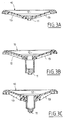
- - les Fig.3A, 3B et 3C sont des coupes longitudinales de modes de réalisation d'un volant suivant l'invention ; et
- - la Fig.4 est une vue de dessous d'un volant selon l'invention.
- Les volants pour véhicules automobiles étant bien connus dans la technique, on ne décrira que ce qui concerne l'invention. Pour le reste le spécialiste de la technique considérée puisera dans les solutions à sa disposition pour faire face aux contraintes qui lui sont opposées tout en atteignant les objectifs qui lui sont assignés.
- Les matières synthétiques chargées de fibres mono-filament ou multi-brins, retordus ou non et éventuellement assemblées en torons, qui sont orientées ou tissées, sont bien connues.
- Il existe des matières synthétiques thermo-durcissables ou thermoplastiques préimprégnées de ce type. Toutefois, il est difficile de les utiliser suivant la technique antérieure pour obtenir des volants qui soient satisfaisants. En particulier, il faut alors se servir de matières plastiques très résistantes et qui sont souvent coûteuses car très spécifiques ou bien il faut les mettre en oeuvre en très grande quantité ce qui ne fait qu'augmenter outre le prix, la mase et le moment d'inertie polaire c'est-à-dire par rapport à l'axe de la colonne de direction.
- Le but de l'invention est de faire face à ce type de difficultés en utilisant un demi produit obtenu à partir d'une matière synthétique dans laquelle sont incorporées des fibres relativement longues qui jouent le rôle de charge.
- Cette matière est utilisée sous forme de flans et lorsqu'on indique dans le présent texte qu'il s'agit de fibres relativement longues il faut entendre des fibres qui ne sont pas interrompues dans le flan mis en oeuvre. De telles fibres peuvent être monofilament ou multi-brins, retordues ou non et assemblées en torons ou câblées. Ces fibres peuvent être orientées ou tissées.
- Les flans dont il est question par la suite sont faits d'une matière synthétique thermoplastique tel que du polypropylène, un polyamide ou d'une matière synthétique thermodurcissable préimprégnée désignée dans la technique sous l'appellation SMC (semi moulding composite).
- Les fibres qui sont incorporées à cette matière synthétique sont par exemple des fibres organiques telles que celles connues dans le commerce sous l'appellation Kevlar, des fibres minérales telles que du verre ou du carbone ou bien même des fibres métalliques.
- De tels flans de demi produit sont, de préférence, obtenus par co-extrusion c'est-à-dire par extrusion simultanée de la matière synthétique et des fibres afin d'obtenir une bonne orientation sans désordre de celle-ci dans les flans de demi produit pour les raisons qui appraîtront par la suite.
- Comme on le voit sur les figures du dessin, un volant 10 comprend un moyeu central 11, une jante périphérique 12 et au moins un bras ou branche 13 approximativement radial reliant le moyeu à la jante.
- Le moyeu 11 destiné à relier le volant à l'extrémité libre de l'habitacle de l'arbre de colonne de direction, est métallique comme classique.
- Pour fabriquer un volant selon l'invention, on utilise un moule 30 composé d'un poinçoin 31 et d'une matrice 32. Dans ce moule est ménagée une empreinte 320 qui correspond à la configuration et à la géométrie du volant 10 à obtenir.
- Comme on le voit, en particulier sur les Fig.1 et 2, on garnit l'empreinte 320 du moule de flans 20 de demi produit selon l'invention. On con forme les différents flans à la géométrie du moule et on les dispose comme par exemple représenté sur la Fig.2. On peut utiliser des flans de nature identique ou de nature différente par leur matière synthétique et/ou leurs fibres et de dimensions identiques ou différentes dans leurs différentes directions, comme illustré.
- Selon l'invention on utilise des flans multiples placés de préférence sur chant dans l'empreinte de telle sorte que les fibres garnissent parfaitement les détails, par exemple des nervures présentes dans l'empreinte.
- Ceci permet de réaliser notamment les ajourages et en même temps de combiner l'orientation, la nature et la densité des fibres pour optimiser la résistance locale aux efforts.
- Comme on le voit en examinant les figures, grâce à la technique de l'invention il est possible d'obtenir le volant directement avec ajours contrairement à ce qui est fait selon la technique antérieure où l'on part non pas de flans mais de feuilles en matière plastique estampable qui sont préalablement ramollies puis estampées et où il est nécessaire de faire les ajours après le moulage.
- Comme on l'observe, selon l'invention on obtient directement les ajours par la disposition et la répartition des flans dans l'empreinte
- Les flans ainsi chargés dans le moule, préalablement ramollis s'il y a lieu, sont alors soumis à un estampage c'est-à-dire qu'ils sont comprimés avec une énergie suffisante et une grande vitesse.
- On constate alors que la matière synthétique à tendance à fluer, voire à se liquéfier et que les fibres suivent l'écoulement de la matière synthètique au cours de l'estampage pour emplir les détails de l'empreinte, la matière synthétique jouant le rôle d'un liant analogue à un mastic.
- Les paramètres de réglage du processus tien-tiennent compte notamment de la rhéologie propre à la matière synthétique, en particulier de sa viscosité par rapport à la vitesse de choc au moment de l'estampage.
- Grâce à l'invention il est possible d'obtenir des nervures, des bords tombés, des arrondis sur le volant.
- Le choix de la forme du moule, des énergies et des vitesses d'estampage, est fonction des équipements à la disposition de l'opérateur, des dimensions des pièces à obtenir et de leur géométrie ainsi que de la nature des matières synthétiques et des fibres utilisées.
- Grâce à l'invention, il est possible d'obtenir un volant où le moyeu métallique est directement prisonnier.
- C'est ce qui est représenté sur la Fig.3A.
- Au lieu d'utiliser un moyeu simple traditionnel il est aussi possible de se servir d'un moyeu associé à un absorbeur d'énergie qui permet encore d'augmenter les conditions de sécurité.
- Sur la Fig.3B, est illustré un volant selon l'invention équipé d'un absorbeur de choc tel que celui qui fait l'objet de la demande de brevet de la Demanderesse intitulée "Volant de direction notamment de véhicule automobile" déposée le 17 avril 1987. On peut remplacer un tel absorbeur d'énergie composite par un absorbeur d'énergie métallique comme illustré sur la Fig.3C.
- Sur la Fig.4 qui représente schématiquement un volant selon l'invention, vu de dessous, on observe le réseau de nervures 15 circulaires, obliques, radiales ou croisées que l'on obtient. Ces nervures renforcées par des fibres longues permettent d'allier résistance et légèreté.
- On voit donc tout l'intérêt de l'invention qui permet d'obtenir en une seule opération un volant totalement en matière synthétique renforcée de fibres longues sans faire appel à des renforts métalliques intérieurs ou extérieurs et où la seule partie métallique est, éventuellement, son moyeu.
- Comme il est courant, le volant suivant l'invention est muni extérieurement d'un revêtement qui lui donne son aspect et son toucher final. Ce revêtement, par exemple en une mousse de polyuréthane, est appliqué de toute manière appropriée classique. Un tel revêtement peut jouer le rôle de "jean" ou bien être recouvert lui-même d'un habillage en cuir naturel ou en synderme.
Claims (15)
Applications Claiming Priority (2)
| Application Number | Priority Date | Filing Date | Title |
|---|---|---|---|
| FR8713323A FR2620996B1 (fr) | 1987-09-25 | 1987-09-25 | Volant allege de direction notamment pour vehicule automobile obtenu a partir de matieres synthetiques renforcees estampables et procede pour sa fabrication |
| FR8713323 | 1987-09-25 |
Publications (2)
| Publication Number | Publication Date |
|---|---|
| EP0309316A1 true EP0309316A1 (fr) | 1989-03-29 |
| EP0309316B1 EP0309316B1 (fr) | 1991-12-18 |
Family
ID=9355250
Family Applications (1)
| Application Number | Title | Priority Date | Filing Date |
|---|---|---|---|
| EP88402313A Expired - Lifetime EP0309316B1 (fr) | 1987-09-25 | 1988-09-14 | Procédé pour la fabrication d'un volant de direction allégé |
Country Status (9)
| Country | Link |
|---|---|
| US (2) | US4875387A (fr) |
| EP (1) | EP0309316B1 (fr) |
| JP (1) | JPH01114568A (fr) |
| KR (1) | KR890004929A (fr) |
| DE (1) | DE3867012D1 (fr) |
| ES (1) | ES2028331T3 (fr) |
| FR (1) | FR2620996B1 (fr) |
| MX (1) | MX170428B (fr) |
| YU (1) | YU47293B (fr) |
Cited By (4)
| Publication number | Priority date | Publication date | Assignee | Title |
|---|---|---|---|---|
| WO1991001874A1 (fr) * | 1989-07-28 | 1991-02-21 | Camplas Technology Limited | Ameliorations relatives a la formation de structures renforcees |
| EP0504963A1 (fr) * | 1991-03-20 | 1992-09-23 | KOLBENSCHMIDT Aktiengesellschaft | Volant de direction |
| FR2774348A1 (fr) | 1998-02-04 | 1999-08-06 | Roulements Soc Nouvelle | Armature de volant a capteur de couple integre ou rapporte pour dispositif de direction de vehicule |
| WO2000044604A1 (fr) * | 1999-01-27 | 2000-08-03 | Trw Automotive Safety Systems Gmbh & Co. Kg | Volant de direction pour vehicule |
Families Citing this family (11)
| Publication number | Priority date | Publication date | Assignee | Title |
|---|---|---|---|---|
| US5243877A (en) * | 1992-03-30 | 1993-09-14 | Ryusaku Numata | Steering wheel rim |
| US5490435A (en) * | 1994-08-25 | 1996-02-13 | Chrysler Corporation | Energy absorbing steering wheel |
| JPH08268288A (ja) * | 1995-03-29 | 1996-10-15 | Toyoda Gosei Co Ltd | ステアリングホイール芯金 |
| JP3118528B2 (ja) * | 1996-01-26 | 2000-12-18 | 東邦レーヨン株式会社 | ステアリングホイールおよびその製造方法 |
| DE29706136U1 (de) * | 1997-03-24 | 1997-06-12 | Petri Ag, 63743 Aschaffenburg | Auf einer Grundplatte befestigte Plakette |
| US5896661A (en) * | 1998-03-10 | 1999-04-27 | General Motors Corporation | Method of making a steering hand wheel |
| DE20101868U1 (de) * | 2001-02-01 | 2001-06-21 | TRW Automotive Safety Systems GmbH & Co. KG, 63743 Aschaffenburg | Fahrzeuglenkrad |
| US20040262805A1 (en) * | 2003-06-30 | 2004-12-30 | Bostick William E. | Leather stylized steering wheel |
| DE102004015529B4 (de) * | 2004-03-30 | 2009-08-27 | Key Safety Systems, Inc., Sterling Heights | Lenkrad für ein Fahrzeug |
| DE102006041386A1 (de) * | 2006-08-30 | 2008-03-13 | Takata-Petri Ag | Lenkrad für ein Fahrzeug und Verfahren zu dessen Herstellung |
| US20090114368A1 (en) * | 2007-11-02 | 2009-05-07 | Minoru Niwa | Heated or cooled steering wheel |
Citations (8)
| Publication number | Priority date | Publication date | Assignee | Title |
|---|---|---|---|---|
| GB1582846A (en) * | 1978-01-30 | 1981-01-14 | Trw Clifford Ltd | Steering wheels |
| EP0022679A1 (fr) * | 1979-07-16 | 1981-01-21 | Ford Motor Company Limited | Assemblage d'un volant de direction |
| FR2513563A1 (fr) * | 1981-09-26 | 1983-04-01 | Kawasaki Yuko Kk | Procede pour fabriquer a la presse des pieces moulees, a partir d'une feuille de matiere composite |
| FR2518479A1 (fr) * | 1981-12-22 | 1983-06-24 | Quillery | Volant d'automobile et son procede de fabrication |
| AU532845B2 (en) * | 1979-11-20 | 1983-10-13 | Albert Fradin | Moulding slow setting material |
| EP0139015A1 (fr) * | 1983-03-15 | 1985-05-02 | Mitsubishi Denki Kabushiki Kaisha | Volant de direction |
| DE3425959A1 (de) * | 1984-07-14 | 1986-01-16 | Kolbenschmidt AG, 7107 Neckarsulm | Kraftfahrzeug-lenkrad |
| EP0173826A1 (fr) * | 1984-09-06 | 1986-03-12 | Toyota Jidosha Kabushiki Kaisha | Noyau en plastique renforcé par fibres pour volant de direction |
Family Cites Families (13)
| Publication number | Priority date | Publication date | Assignee | Title |
|---|---|---|---|---|
| US509259A (en) * | 1893-11-21 | Felly for wheels | ||
| US1370023A (en) * | 1921-03-01 | X h house electric | ||
| US1421434A (en) * | 1921-02-26 | 1922-07-04 | Julian B La Pierre | Rim for steering wheels |
| US1484311A (en) * | 1923-02-28 | 1924-02-19 | Frank V Tischer | Apparatus and method of making laminated structures |
| US1593201A (en) * | 1925-11-03 | 1926-07-20 | Frank V Tischer | Steering wheel |
| US1847414A (en) * | 1928-03-09 | 1932-03-01 | Pouvailsmith Corp | Method of making wheels |
| US2187604A (en) * | 1935-11-29 | 1940-01-16 | Standard Products Co | Automobile steering wheel construction |
| US2409645A (en) * | 1944-10-21 | 1946-10-22 | Canal Nat Bank | Resin-fiber article and method of making the same |
| BE878427A (nl) * | 1979-02-23 | 1980-02-25 | Kelsey Hayes Co | Draaimoment-overbrengorgaan |
| US4419908A (en) * | 1981-10-26 | 1983-12-13 | Kelsey-Hayes Co. | Mold and method of making spoked wheels and product of same |
| US4635500A (en) * | 1982-12-10 | 1987-01-13 | Shell Oil Company | Epoxy steering wheel |
| JPS60105565U (ja) * | 1983-12-25 | 1985-07-18 | トヨタ自動車株式会社 | ステアリングホイ−ル |
| JPS60236871A (ja) * | 1984-05-09 | 1985-11-25 | Morio Arai | 円形枠及びその製造方法 |
-
1987
- 1987-09-25 FR FR8713323A patent/FR2620996B1/fr not_active Expired - Lifetime
-
1988
- 1988-09-14 DE DE8888402313T patent/DE3867012D1/de not_active Expired - Lifetime
- 1988-09-14 EP EP88402313A patent/EP0309316B1/fr not_active Expired - Lifetime
- 1988-09-14 ES ES198888402313T patent/ES2028331T3/es not_active Expired - Lifetime
- 1988-09-21 MX MX013095A patent/MX170428B/es unknown
- 1988-09-22 YU YU178388A patent/YU47293B/sh unknown
- 1988-09-23 US US07/248,073 patent/US4875387A/en not_active Expired - Fee Related
- 1988-09-23 KR KR1019880012342A patent/KR890004929A/ko not_active Withdrawn
- 1988-09-26 JP JP63240642A patent/JPH01114568A/ja active Pending
-
1989
- 1989-08-29 US US07/401,478 patent/US4975235A/en not_active Expired - Fee Related
Patent Citations (8)
| Publication number | Priority date | Publication date | Assignee | Title |
|---|---|---|---|---|
| GB1582846A (en) * | 1978-01-30 | 1981-01-14 | Trw Clifford Ltd | Steering wheels |
| EP0022679A1 (fr) * | 1979-07-16 | 1981-01-21 | Ford Motor Company Limited | Assemblage d'un volant de direction |
| AU532845B2 (en) * | 1979-11-20 | 1983-10-13 | Albert Fradin | Moulding slow setting material |
| FR2513563A1 (fr) * | 1981-09-26 | 1983-04-01 | Kawasaki Yuko Kk | Procede pour fabriquer a la presse des pieces moulees, a partir d'une feuille de matiere composite |
| FR2518479A1 (fr) * | 1981-12-22 | 1983-06-24 | Quillery | Volant d'automobile et son procede de fabrication |
| EP0139015A1 (fr) * | 1983-03-15 | 1985-05-02 | Mitsubishi Denki Kabushiki Kaisha | Volant de direction |
| DE3425959A1 (de) * | 1984-07-14 | 1986-01-16 | Kolbenschmidt AG, 7107 Neckarsulm | Kraftfahrzeug-lenkrad |
| EP0173826A1 (fr) * | 1984-09-06 | 1986-03-12 | Toyota Jidosha Kabushiki Kaisha | Noyau en plastique renforcé par fibres pour volant de direction |
Cited By (6)
| Publication number | Priority date | Publication date | Assignee | Title |
|---|---|---|---|---|
| WO1991001874A1 (fr) * | 1989-07-28 | 1991-02-21 | Camplas Technology Limited | Ameliorations relatives a la formation de structures renforcees |
| EP0504963A1 (fr) * | 1991-03-20 | 1992-09-23 | KOLBENSCHMIDT Aktiengesellschaft | Volant de direction |
| US5445048A (en) * | 1991-03-20 | 1995-08-29 | Kolbenschmidt Aktiengesellschaft | Steering wheel |
| FR2774348A1 (fr) | 1998-02-04 | 1999-08-06 | Roulements Soc Nouvelle | Armature de volant a capteur de couple integre ou rapporte pour dispositif de direction de vehicule |
| WO1999039962A1 (fr) | 1998-02-04 | 1999-08-12 | S.N.R. Roulements | Armature de volant a capteur de couple integre ou rapporte pour dispositif de direction de vehicule |
| WO2000044604A1 (fr) * | 1999-01-27 | 2000-08-03 | Trw Automotive Safety Systems Gmbh & Co. Kg | Volant de direction pour vehicule |
Also Published As
| Publication number | Publication date |
|---|---|
| DE3867012D1 (de) | 1992-01-30 |
| EP0309316B1 (fr) | 1991-12-18 |
| FR2620996A1 (fr) | 1989-03-31 |
| MX170428B (es) | 1993-08-23 |
| US4975235A (en) | 1990-12-04 |
| KR890004929A (ko) | 1989-05-10 |
| YU178388A (sh) | 1993-11-16 |
| US4875387A (en) | 1989-10-24 |
| ES2028331T3 (es) | 1992-07-01 |
| FR2620996B1 (fr) | 1990-01-26 |
| JPH01114568A (ja) | 1989-05-08 |
| YU47293B (sh) | 1995-01-31 |
Similar Documents
| Publication | Publication Date | Title |
|---|---|---|
| EP0309316B1 (fr) | Procédé pour la fabrication d'un volant de direction allégé | |
| EP0604297B1 (fr) | Pale en composite thermoplastique, notamment pour rotor arrière caréné d'hélicoptère, et son procédé de fabrication avec étape d'injection | |
| EP0604298B1 (fr) | Pale en composite thermoplastique, notamment pour rotor arrière caréné d'hélicoptère, et son procédé de fabrication | |
| EP2911866B1 (fr) | Procede de moulage de materiau composite dans lequel un tissu de fibres est tendu dans un cadre de maintien avant injection d'une matrice | |
| WO2016020257A1 (fr) | Procédé de fabrication d'une pièce renforcée comportant un matériau composite | |
| EP2433024B1 (fr) | Procede de fabrication d'une bielle en materiau composite | |
| EP0329542B1 (fr) | Procédé de fabrication d'un volant de direction, notamment pour véhicule automobile | |
| EP0332495B1 (fr) | Procédé de fabrication de pièces de carrosserie d'automobile, notamment d'aileron ou becquet arrière, et pièces obtenues par mise en oeuvre de ce procédé | |
| EP2613925B1 (fr) | Procede de fabrication de pieces en materiaux composites, avec revetement tresse | |
| FR3009705A1 (fr) | Doublure interieure renforcee de hayon, notamment pour vehicule automobile | |
| EP3521001B1 (fr) | Pièce préimprégnée comprenant une couche principale et une couche de renfort | |
| EP0979165B1 (fr) | Embouts pour chaussures de securite en matiere plastique composite et leur procede de fabrication | |
| FR2749535A1 (fr) | Piece a base de materiau thermoplastique pour vehicule automobile et procede de fabrication de cette piece | |
| FR3050686B1 (fr) | Roue de vehicule automobile comportant un voile renforce par des materiaux composites | |
| EP0802850B1 (fr) | Panneau de matiere tel que par exemple panneau de portiere de vehicule presentant des renforts et une poignee | |
| FR3052397A1 (fr) | Renfort de choc lateral en matiere composite pour porte de vehicule automobile | |
| EP0914780B1 (fr) | Armature de rigidification pour soutien-gorge réalisée en matériau thermoplastique ou thermodurcissable comportant des fibres longitudinales de rigidification | |
| WO2016156750A1 (fr) | Procédé de fabrication d'un insert d'un ouvrant de véhicule automobile | |
| FR2724214A1 (fr) | Piece, planiforme et/ou filiforme renforcee d'une ou plusieurs nervures dans sa masse | |
| CA1123712A (fr) | Dispositif a rayons, et methode de fabrication connexe | |
| FR2784622A1 (fr) | Rayon composite pour une roue de bicyclette et son procede de fabrication | |
| FR2724131A1 (fr) | Procede de fabrication d'une piece moulee presentant au moins une excroissance | |
| JPS62263031A (ja) | 長繊維強化樹脂製ステアリングホイ−ル芯の製造方法 |
Legal Events
| Date | Code | Title | Description |
|---|---|---|---|
| PUAI | Public reference made under article 153(3) epc to a published international application that has entered the european phase |
Free format text: ORIGINAL CODE: 0009012 |
|
| AK | Designated contracting states |
Kind code of ref document: A1 Designated state(s): DE ES GB IT SE |
|
| 17P | Request for examination filed |
Effective date: 19890227 |
|
| 17Q | First examination report despatched |
Effective date: 19900612 |
|
| GRAA | (expected) grant |
Free format text: ORIGINAL CODE: 0009210 |
|
| AK | Designated contracting states |
Kind code of ref document: B1 Designated state(s): DE ES GB IT SE |
|
| GBT | Gb: translation of ep patent filed (gb section 77(6)(a)/1977) | ||
| ITF | It: translation for a ep patent filed | ||
| REF | Corresponds to: |
Ref document number: 3867012 Country of ref document: DE Date of ref document: 19920130 |
|
| REG | Reference to a national code |
Ref country code: ES Ref legal event code: FG2A Ref document number: 2028331 Country of ref document: ES Kind code of ref document: T3 |
|
| PLBE | No opposition filed within time limit |
Free format text: ORIGINAL CODE: 0009261 |
|
| STAA | Information on the status of an ep patent application or granted ep patent |
Free format text: STATUS: NO OPPOSITION FILED WITHIN TIME LIMIT |
|
| 26N | No opposition filed | ||
| EAL | Se: european patent in force in sweden |
Ref document number: 88402313.6 |
|
| PGFP | Annual fee paid to national office [announced via postgrant information from national office to epo] |
Ref country code: ES Payment date: 19960917 Year of fee payment: 9 |
|
| PGFP | Annual fee paid to national office [announced via postgrant information from national office to epo] |
Ref country code: SE Payment date: 19960920 Year of fee payment: 9 |
|
| PG25 | Lapsed in a contracting state [announced via postgrant information from national office to epo] |
Ref country code: SE Free format text: LAPSE BECAUSE OF NON-PAYMENT OF DUE FEES Effective date: 19970915 Ref country code: ES Free format text: LAPSE BECAUSE OF THE APPLICANT RENOUNCES Effective date: 19970915 |
|
| EUG | Se: european patent has lapsed |
Ref document number: 88402313.6 |
|
| REG | Reference to a national code |
Ref country code: GB Ref legal event code: 732E |
|
| REG | Reference to a national code |
Ref country code: ES Ref legal event code: FD2A Effective date: 20001102 |
|
| REG | Reference to a national code |
Ref country code: GB Ref legal event code: IF02 |
|
| PGFP | Annual fee paid to national office [announced via postgrant information from national office to epo] |
Ref country code: DE Payment date: 20030908 Year of fee payment: 16 |
|
| PGFP | Annual fee paid to national office [announced via postgrant information from national office to epo] |
Ref country code: GB Payment date: 20030909 Year of fee payment: 16 |
|
| PG25 | Lapsed in a contracting state [announced via postgrant information from national office to epo] |
Ref country code: GB Free format text: LAPSE BECAUSE OF NON-PAYMENT OF DUE FEES Effective date: 20040914 |
|
| PG25 | Lapsed in a contracting state [announced via postgrant information from national office to epo] |
Ref country code: DE Free format text: LAPSE BECAUSE OF NON-PAYMENT OF DUE FEES Effective date: 20050401 |
|
| GBPC | Gb: european patent ceased through non-payment of renewal fee |
Effective date: 20040914 |
|
| PG25 | Lapsed in a contracting state [announced via postgrant information from national office to epo] |
Ref country code: IT Free format text: LAPSE BECAUSE OF NON-PAYMENT OF DUE FEES;WARNING: LAPSES OF ITALIAN PATENTS WITH EFFECTIVE DATE BEFORE 2007 MAY HAVE OCCURRED AT ANY TIME BEFORE 2007. THE CORRECT EFFECTIVE DATE MAY BE DIFFERENT FROM THE ONE RECORDED. Effective date: 20050914 |