EP0309806A2 - Moule pour la fabrication de rouge à lèvres - Google Patents
Moule pour la fabrication de rouge à lèvres Download PDFInfo
- Publication number
- EP0309806A2 EP0309806A2 EP88114969A EP88114969A EP0309806A2 EP 0309806 A2 EP0309806 A2 EP 0309806A2 EP 88114969 A EP88114969 A EP 88114969A EP 88114969 A EP88114969 A EP 88114969A EP 0309806 A2 EP0309806 A2 EP 0309806A2
- Authority
- EP
- European Patent Office
- Prior art keywords
- mold
- separating surface
- lipstick
- axis
- fitting means
- Prior art date
- Legal status (The legal status is an assumption and is not a legal conclusion. Google has not performed a legal analysis and makes no representation as to the accuracy of the status listed.)
- Withdrawn
Links
- 238000004519 manufacturing process Methods 0.000 title description 15
- 239000000463 material Substances 0.000 claims abstract description 12
- 238000005266 casting Methods 0.000 claims description 11
- 238000001746 injection moulding Methods 0.000 description 3
- 239000007788 liquid Substances 0.000 description 3
- 239000000203 mixture Substances 0.000 description 3
- 238000000926 separation method Methods 0.000 description 3
- NIXOWILDQLNWCW-UHFFFAOYSA-N acrylic acid group Chemical group C(C=C)(=O)O NIXOWILDQLNWCW-UHFFFAOYSA-N 0.000 description 2
- 239000002537 cosmetic Substances 0.000 description 2
- 238000005429 filling process Methods 0.000 description 2
- 238000011078 in-house production Methods 0.000 description 2
- 239000000470 constituent Substances 0.000 description 1
- 238000010276 construction Methods 0.000 description 1
- 238000001816 cooling Methods 0.000 description 1
- 239000013078 crystal Substances 0.000 description 1
- 239000000975 dye Substances 0.000 description 1
- 238000000034 method Methods 0.000 description 1
- 235000011837 pasties Nutrition 0.000 description 1
- 230000008092 positive effect Effects 0.000 description 1
- 238000007711 solidification Methods 0.000 description 1
- 230000008023 solidification Effects 0.000 description 1
- 239000007858 starting material Substances 0.000 description 1
- 239000012780 transparent material Substances 0.000 description 1
Images
Classifications
-
- A—HUMAN NECESSITIES
- A45—HAND OR TRAVELLING ARTICLES
- A45D—HAIRDRESSING OR SHAVING EQUIPMENT; EQUIPMENT FOR COSMETICS OR COSMETIC TREATMENTS, e.g. FOR MANICURING OR PEDICURING
- A45D40/00—Casings or accessories specially adapted for storing or handling solid or pasty toiletry or cosmetic substances, e.g. shaving soaps or lipsticks
- A45D40/16—Refill sticks; Moulding devices for producing sticks
Definitions
- the purpose of the present invention is to provide an easy-to-use and, at the same time, shapely, thus aesthetically appealing casting mold for the in-house production of lipsticks. It should offer the possibility of being able to control the product, i.e. the poured lipstick, well during production, in order to be able to observe and check the quality of the later product already during the initial stages of production. Such a mold should also be easy to use and clean. It should enable easy filling and also a convenient removal of the finished lipstick. The finished product should look as neat as possible, if not professional, so it should differ as little as possible from the ready-made lipsticks on the market.
- the mold is therefore generally suitable for consumer classes who, on the one hand, have fun making a cosmetic product, in this case a lipstick, and on the other hand appreciate the money advantage that is associated with self-production compared to commercially available products.
- the invention has for its object to provide an easy-to-use, namely easy to fill, easy to control in the filling state until the solidified lipstick is removed, which allows easy removal of the finished lipstick and overall the manufacturing steps for the manufacture of Lipstick relieved with home improvement tools.
- the casting mold consists of two largely identical, preferably identical mold halves, which have fitting means for mutual, exact fitting contact, which touch in the assembled state on a separating surface and, on the one hand, a largely cylindrical, lipstick-shaped, open-topped Limit the mold cavity, the axis of which lies in the separating surface and, on the other hand, limit an overlying filling area, and that both mold halves are made of a transparent material.
- the fitting means serve to match the two mold halves clearly and precisely so that they form the casting mold.
- the two mold halves touch on a dividing surface, thereby limiting the mold cavity for the lipstick.
- the separating surface lies on the axis of the largely cylindrical mold cavity, whereby the separation of the two mold halves from one another and the removal of the cast lipstick are particularly simplified after the production and solidification of a lipstick.
- a filling area is located above the entrance area of the mold cavity. It serves to simplify the filling into the rather narrow mold cavity, it essentially has the function of a funnel, so it serves to make more liquid during the casting process Material can be filled in the unit of time than can actually flow through the circular inlet area into the mold cavity. In addition, the amount to be filled in does not have to be measured exactly, it can certainly be larger than is required for the actual lipstick.
- the superfluous material remains in the filling area and solidifies together with the material that is in the mold cavity. The material in the filling area can later be cut away, for example with a sharp knife or a razor blade. It makes it easier to remove the solidified lipstick body because it can be used as a handle.
- due to the construction only the rear end of the lipstick becomes imprecise, while the front end, which is located in the mold below, and the entire jacket are precisely cast in the selected production.
- the manufacture of the two mold halves from a crystal-clear material, for example acrylic by injection molding makes it possible to be able to closely monitor and control the production steps during manufacture. On the one hand, it can be followed whether the mold cavity fills without bubbles, whether enough has been filled in, and later it can be observed without opening the mold whether the filled mass has already solidified. Due to the crystal-clear design, you can also see whether the casting process went well, i.e. whether streaks have formed or not.
- the crystal-clear design gives the overall shape a special aesthetic appeal and increases the pleasure of working with this mold.
- the fitting means can be of any design, so it is possible, for example, that protrusions protrude from one mold half on the separating surface, which engage in correspondingly adapted recesses in the other mold half or come to rest on side surfaces.
- the two mold halves differ, if at all, only in terms of their fitting means.
- the fitting means can be designed so that the two mold halves are completely identical.
- different but cooperating fitting means are provided on both sides of the axis of the mold cavity lying in the separating surface. These must be in places which are fold symmetrical to the axis.
- the two mold halves are largely cuboid, the separating surface is square, in it the mold channel is provided in the center.
- each mold half has a footprint that is perpendicular to the axis of the mold cavity and is in the same plane as the footprint of the other mold half. This enables the two mold halves to stand upright independently and to be joined together in this state, for example when they are on a table top. Furthermore, it is possible that the mold itself stands, that is, it does not have to be held during the filling process and does not have to be supported later in the refrigerator.
- the aforementioned production of the mold halves by injection molding ensures that the inner surfaces of the two mold channels forming the mold cavity are extremely smooth, so that the finished product, i.e. the lipstick, has the preferred, completely smooth surface, which particularly emphasizes its components and on one professionally manufactured product.
- the separating surfaces are preferably relatively wide at the sides and downwards, so that a larger distance of several millimeters, for example 10 mm, remains between the edge of the mold channel and the side surface or standing surface of the mold.
- This has the following advantage: If the two mold halves do not touch exactly in the area of the mold cavity, some of the cast material flows between the two parting surfaces. However, the gaps there are narrow, the liquid starting material for the lipstick is viscous. Because of the be written greater distance cools the material faster before it can run out of the mold on the side surfaces or in particular in the area of the footprint.
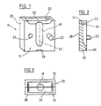
- the mold for lipsticks consists of two essentially cuboidal mold halves 10, 12, which are completely identical. They are made of crystal clear acrylic by injection molding.
- the surface facing the viewer in FIG. 1 is a separating surface 14.
- a molded channel 16 is incorporated, which has the shape of a half, axially cut lipstick.
- a mold cavity 18 is formed, which has a lipstick shape, that is to say is largely cylindrical.
- the axis 20 of this body lies in the separating surface 14. This axis also forms - with the exception of the fitting means 22, 24 to be described later - a line for mirror symmetry of the mold halves 10 and 12, respectively.
- the fitting means 22, 24 are provided at mirror-image locations to the folding symmetry line (axis 20), but the mirror image pairs are each designed differently, that is, a negative fitting means on one side is opposite a positive fitting means arranged in a mirror image on the other side.
- a pin 22 is arranged to the right of the axis 20 and jumps forward at right angles from the separating surface 14. It is on the left side of the axis 20 assigned a correspondingly adapted blind bore 24.
- the pin 22 and the blind bore 24 are matched to one another in such a way that, on the one hand, a precise fit is achieved in the composition of the two mold halves 10, 12 and, on the other hand, clamping is achieved, which makes it difficult to open the mold unintentionally.
- the fitting means can also be designed in another form. If the identity of both mold halves is dispensed with, the mold half 10 shown in FIG. 1 can only have blind holes 24, for example, while the other mold half 12 has two pins 22 as shown in FIG. 2. Deviating from the exemplary embodiment shown, more than just a pair of fitting means 22, 24 can also be provided.
- the fitting means can be arranged on the edge, project significantly less than the pin 22 shown and can also be made smaller than this.
- the separating surface 14 is a square with an edge length of 5 cm.
- the cuboid has a thickness of 12 mm. It is laterally delimited by side surfaces 26. Its rear surface 28 is completely flat and unprocessed. Its lower surface is referred to as the standing surface 30, it runs at right angles to the axis 20.
- a recess 32 is machined into an upper side 31, which together with the identical recess of the other mold half 12 forms a funnel-like filling area 34, the deepest point of which is a largely circular inlet edge 36 , from which the mold cavity 18 extends downward.
- the volume of the filling area 34 is selected such that it essentially corresponds to the volume of the mold cavity 18.
- the mold cavity itself has a diameter of approximately 12 mm and a total depth of approximately 40 mm in its upper, largely cylindrical region.
- the downward-pointing region of the mold cavity 18, in which the tip of the lipstick is later formed is shaped like an ellipsoid.
- a different shape for example a slight bevel or the like - depending on the desired shape of the tip of the lipstick - can also be provided here.
- each mold half 10, 12 has a small bevel 38, starting from the standing surface 30, which offers a separation aid with the corresponding bevel 38 of the other mold half 12. Since the bevel runs at an angle to the parting surface, a part of the two mold halves can be separated by driving an object into the closed form, in which a solidified lipstick is located. The advantage is that the separation begins in the area of the tip of the poured lipstick, so that the demolding is best there.
- det has about 6 mm in diameter and projects about 7 mm freely.
- the blind bore 24 is designed accordingly, but approximately 1 to 2 mm deeper.
- Fig. 3 shows a view from above of the closed form.
- the filling area 34 which is essentially trough-shaped, can be seen.
- the mold cavity 18, which appears largely circular in this illustration, is located in the center and downwards. From FIG. 3 it can be seen how the material can reach and fill the mold cavity 18 below when pouring material into the filling region 34.
- the filling area 34 serves as a depot at the end of the filling process, it holds back excess material without the risk that it can overflow laterally.
- the front end of the pin 22 can be made slightly spherical so that it snaps into the blind bore 24 when it is inserted.
- Other closing means for example magnets, are also possible.
Landscapes
- Cosmetics (AREA)
Applications Claiming Priority (2)
| Application Number | Priority Date | Filing Date | Title |
|---|---|---|---|
| DE8713141U | 1987-09-30 | ||
| DE8713141U DE8713141U1 (de) | 1987-09-30 | 1987-09-30 | Gußform für die Herstellung von Lippenstiften |
Publications (2)
| Publication Number | Publication Date |
|---|---|
| EP0309806A2 true EP0309806A2 (fr) | 1989-04-05 |
| EP0309806A3 EP0309806A3 (fr) | 1990-07-04 |
Family
ID=6812601
Family Applications (1)
| Application Number | Title | Priority Date | Filing Date |
|---|---|---|---|
| EP88114969A Withdrawn EP0309806A3 (fr) | 1987-09-30 | 1988-09-14 | Moule pour la fabrication de rouge à lèvres |
Country Status (2)
| Country | Link |
|---|---|
| EP (1) | EP0309806A3 (fr) |
| DE (1) | DE8713141U1 (fr) |
Cited By (1)
| Publication number | Priority date | Publication date | Assignee | Title |
|---|---|---|---|---|
| DE4445231A1 (de) * | 1994-12-17 | 1996-06-20 | Schwan Stabilo Schwanhaeusser | Verfahren zum Gießen einer Kosmetikmine eines Kosmetikstiftes und Vorrichtung zur Durchführung des Verfahrens |
Family Cites Families (3)
| Publication number | Priority date | Publication date | Assignee | Title |
|---|---|---|---|---|
| FR1055222A (fr) * | 1952-04-26 | 1954-02-17 | Procédé de préparation et de présentation artistique de bâtonnets de fard et produits analogues, et bâtonnet obtenu par ce procédé | |
| DE8117491U1 (de) * | 1981-06-12 | 1981-10-29 | Bartos, Jiři, 6457 Maintail | Formvorrichtung fuer pastoese, langgestreckte formlinge, insbesondere lippenstifte o.dgl. |
| US4543702A (en) * | 1984-05-14 | 1985-10-01 | Satoh Seiki Co., Ltd. | Fully automatic method and apparatus for assembling stick-type cosmetics |
-
1987
- 1987-09-30 DE DE8713141U patent/DE8713141U1/de not_active Expired
-
1988
- 1988-09-14 EP EP88114969A patent/EP0309806A3/fr not_active Withdrawn
Cited By (2)
| Publication number | Priority date | Publication date | Assignee | Title |
|---|---|---|---|---|
| DE4445231A1 (de) * | 1994-12-17 | 1996-06-20 | Schwan Stabilo Schwanhaeusser | Verfahren zum Gießen einer Kosmetikmine eines Kosmetikstiftes und Vorrichtung zur Durchführung des Verfahrens |
| DE4445231C2 (de) * | 1994-12-17 | 2003-01-02 | Schwan Stabilo Cosmetics Gmbh | Vorderteil eines Kosmetikstiftes, Verwendung des Vorderteils, und Kosmetikstift mit einem solchen Vorderteil |
Also Published As
| Publication number | Publication date |
|---|---|
| DE8713141U1 (de) | 1988-01-07 |
| EP0309806A3 (fr) | 1990-07-04 |
Similar Documents
| Publication | Publication Date | Title |
|---|---|---|
| DE3113294C2 (fr) | ||
| DE956356C (de) | Maschine zum Spritzen von thermoplastischen Massen | |
| DE68921577T2 (de) | Verfahren zum Herstellen eines Schiebers zur Verwendung in einem Reissverschluss. | |
| DE2252201A1 (de) | Vorrichtung zum herstellen von formteilen aus schnell miteinander reagierenden chemischen komponenten | |
| DE3346228A1 (de) | Zusammenklappbarer formkern | |
| DE3906716C2 (fr) | ||
| DE3227276C2 (de) | Vorrichtung zur Herstellung einer Kette imn Gießverfahren | |
| DE1929875A1 (de) | Werkzeug zum Umformen,insbesondere Spritzgusswerkzeug | |
| DE3635247A1 (de) | Verfahren zur herstellung eines aus einer geschlitzten metallhuelse und einer ummantelung bestehenden bauteils und nach dem verfahren hergestelltes bauteil | |
| DE617379C (de) | Pressform zum Herstellen von Gegenstaenden aus Kunstharz oder anderen plastischen Massen | |
| EP0309806A2 (fr) | Moule pour la fabrication de rouge à lèvres | |
| DE10359607A1 (de) | Einspritzformsystem mit einem entfernbaren, angussabmachenden In-Mould-Einsatz | |
| DE3726996A1 (de) | Verfahren und vorrichtung zur herstellung von minen fuer kosmetikstifte u. dgl. | |
| DE1163527B (de) | Verfahren zur Herstellung einer aus thermoplastischem Kunststoff bestehenden Verschlusskappe | |
| DE1767916B1 (de) | Kerze,insbesondere Stumpenkerze,und Verfahren zu deren Herstellung | |
| DE8030933U1 (de) | Messer mit zurueckziehbarer klinge und zweiteilige form zur herstellung des handgriffs dieses messers | |
| DE569118C (de) | Vorrichtung zum Herstellen von Wandkacheln mit eingelassener Seifenschale oder einem aehnlichen Gegenstand aus keramischer Masse | |
| DE2200275A1 (de) | Baustein und Verfahren zu dessen Herstellung | |
| DE112018007070T5 (de) | Spritzgussform | |
| DE3521814A1 (de) | Verfahren zur herstellung eines kammkaefigs fuer ein waelzlager, spritz-, giess- oder pressform zur durchfuehrung des verfahrens und nach dem verfahren hergestellter kaefig | |
| DE1114027B (de) | Mehrteilige Spritzgussform zur Herstellung von Hohlkoerpern aus thermoplastischem Kunststoff | |
| DE727954C (de) | Vulkanisierform zum Herstellen eines Kautschukmetallagers | |
| DE3208610A1 (de) | Verfahren und vorrichtung zum herstellen eines streusiebes aus kunststoff | |
| DE816008C (de) | Verfahren zur Herstellung von Spritzgussscharnieren | |
| DE511786C (de) | Verfahren zum einseitigen Schliessen von mit Vorspruengen oder Stegen versehenen, von der Strangpresse abgeschnittenen Hohlsteinen |
Legal Events
| Date | Code | Title | Description |
|---|---|---|---|
| PUAI | Public reference made under article 153(3) epc to a published international application that has entered the european phase |
Free format text: ORIGINAL CODE: 0009012 |
|
| AK | Designated contracting states |
Kind code of ref document: A2 Designated state(s): AT BE CH DE ES FR GB GR IT LI LU NL SE |
|
| RBV | Designated contracting states (corrected) |
Designated state(s): AT BE CH DE FR GB IT LI NL |
|
| PUAL | Search report despatched |
Free format text: ORIGINAL CODE: 0009013 |
|
| AK | Designated contracting states |
Kind code of ref document: A3 Designated state(s): AT BE CH DE FR GB IT LI NL |
|
| STAA | Information on the status of an ep patent application or granted ep patent |
Free format text: STATUS: THE APPLICATION IS DEEMED TO BE WITHDRAWN |
|
| 18D | Application deemed to be withdrawn |
Effective date: 19910105 |