EP0309822A1 - Métal de base avec cordon de soudure - Google Patents
Métal de base avec cordon de soudure Download PDFInfo
- Publication number
- EP0309822A1 EP0309822A1 EP88115116A EP88115116A EP0309822A1 EP 0309822 A1 EP0309822 A1 EP 0309822A1 EP 88115116 A EP88115116 A EP 88115116A EP 88115116 A EP88115116 A EP 88115116A EP 0309822 A1 EP0309822 A1 EP 0309822A1
- Authority
- EP
- European Patent Office
- Prior art keywords
- bead
- substrate
- metallic substrate
- set forth
- deposit
- Prior art date
- Legal status (The legal status is an assumption and is not a legal conclusion. Google has not performed a legal analysis and makes no representation as to the accuracy of the status listed.)
- Ceased
Links
Images

Classifications
-
- B—PERFORMING OPERATIONS; TRANSPORTING
- B23—MACHINE TOOLS; METAL-WORKING NOT OTHERWISE PROVIDED FOR
- B23K—SOLDERING OR UNSOLDERING; WELDING; CLADDING OR PLATING BY SOLDERING OR WELDING; CUTTING BY APPLYING HEAT LOCALLY, e.g. FLAME CUTTING; WORKING BY LASER BEAM
- B23K9/00—Arc welding or cutting
-
- B—PERFORMING OPERATIONS; TRANSPORTING
- B23—MACHINE TOOLS; METAL-WORKING NOT OTHERWISE PROVIDED FOR
- B23K—SOLDERING OR UNSOLDERING; WELDING; CLADDING OR PLATING BY SOLDERING OR WELDING; CUTTING BY APPLYING HEAT LOCALLY, e.g. FLAME CUTTING; WORKING BY LASER BEAM
- B23K9/00—Arc welding or cutting
- B23K9/04—Welding for other purposes than joining, e.g. built-up welding
-
- B—PERFORMING OPERATIONS; TRANSPORTING
- B23—MACHINE TOOLS; METAL-WORKING NOT OTHERWISE PROVIDED FOR
- B23K—SOLDERING OR UNSOLDERING; WELDING; CLADDING OR PLATING BY SOLDERING OR WELDING; CUTTING BY APPLYING HEAT LOCALLY, e.g. FLAME CUTTING; WORKING BY LASER BEAM
- B23K35/00—Rods, electrodes, materials, or media, for use in soldering, welding, or cutting
- B23K35/22—Rods, electrodes, materials, or media, for use in soldering, welding, or cutting characterised by the composition or nature of the material
- B23K35/24—Selection of soldering or welding materials proper
- B23K35/32—Selection of soldering or welding materials proper with the principal constituent melting at more than 1550°C
- B23K35/327—Selection of soldering or welding materials proper with the principal constituent melting at more than 1550°C comprising refractory compounds, e.g. carbides
Definitions
- This invention relates to a metallic substrate having a surface and a weld bead deposit on said surface. More particularly, this invention relates to a metallic substrate in which the surface on which the weld bead is deposited is narrow.
- U.S. Patents 3803380 and 4122327 describe techniques of using a plasma-flame burner for depositing a flow of powdered metal onto a substrate.
- U.S. 4142089 it has been known to use a pulsed mode of arc heating in a plasma gun sprayer for applying a coating of powdered material onto a substrate.
- U.S. Patent 3781508 it has been known to use a pulsed weld current with a transferred arc in order to form a coating from a consumable electrode.
- controlled arc welding techniques have also been known to use a pulsating arc current to form a deposit from an electrode such as described in U.S. Patents 3,449,544; 3,521,027; 3,622,744; 3,666,906 and 3,683,149.
- the deposits which have been obtained have generally had a thickness for a single pass in the range of from 0.020 inch to 0.250 inch and a width down to 0.0625 inch.
- the known processes have been unable to deposit upon substrate widths of 0.100 inch and less without significant melting of the substrate or the use of elaborate chilling devices.
- deposit widths of less than 0.125 inch a ratio of substrate width to a deposit width of 2.5 to 1 is typically maintained in order to provide a suitable base for the hardfacing material and a satisfactory heat sink to prevent the hardfacing material from excessively mixing or diluting with the substrate material and from spilling off the edges.
- the deposit widths of less than 0.075 inch are considered unsuitable for these processes.
- the invention provides a welding apparatus and method for depositing wear surfacing material on a metallic substrate, and particularly on very narrow surfaces of a substrate by use of a plasma transferred arc technique coupled with pulsing of the transferred arc to lay down powder metal into a bead deposit.
- the apparatus includes a welding torch, a non-consumable electrode, a pilot arc welding power source, a main arc power source and a pulse control device.
- the welding torch is constructed with a central passage for receiving the non-consumable electrode and a flow of inert gas, a second passage concentric to and about the central passage for receiving a flow of powdered metal and a third passage concentric to and about the second passage for receiving a flow of shielding gas.
- the pilot arc welding power source is connected to and between the electrode and the torch in order to establish an electric arc therebetween.
- the main arc power source is connected to and between the electrode and the substrate to establish an electric arc therebetween as well as a plasma plume of the flow of inert gas between the electrode and the substrate.
- the pulse control device is connected to the main arc power source for pulsing the power source in order to control the amplitude and duration of the power supplied from the main arc power source.
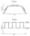
- the control device serves to pulse the current between a main current level and a lower auxiliary current level on a periodic basis.
- the main current level or amplitude is provided to create a weld puddle on the substrate and to fuse the powdered metal.
- the auxiliary current level or amplitude is provided to allow the previously created puddle to solidify thus creating a series of overlapping weld deposits. Variations in the current amplitude as well as the amplitude duration provide a very precise control over the weld deposit geometry and reduced heat input to the base material.This permits the creation of usable hardfacing deposits on substrates with narrow section widths.
- the method provided by the invention comprises the steps of establishing a transferred arc between a non-consumable electrode and a narrow surface of a workpiece, forming a plasma plume of inert gas in the arc, feeding a flow of powdered metal into the plasma plume while moving the electrode along the workpiece for depositing the powdered metal along the narrow surface of the workpiece and pulsing the welding current to the electrode and workpiece between a main current level and a lower auxiliary current level during movement of the electrode in order to effect a series of overlapping weld deposits along the narrow surface of the workpiece.
- the bead deposit which is formed by the overlapping deposits may have a thickness of from 0.010 inch to 0.125 inch for a single pass as well as a width of from 0.020 inch to 0.125 inch. Further, the ratio of bead height to bead width may be in the range of from 0.5:1 to 2:1 for a single pass. Still further, the ratio of substrate width to deposit width may vary from 0.5 to 1.0.
- the invention also provides a metallic substrate having a narrow surface and a weld bead deposit on the narrow surface which is characterized in that the bead is formed of a series of overlapping weld deposits.
- the molten zone formed on the substrate is constantly being created, growing in size, shrinking in size and solidifying completely.
- overlay material By adding overlay material at the appropriate time, the major portions of the heat input supplied by the welding torch can be utilized to melt the powder and only minimum amounts of this heat are directed into the substrate material. This reduces melting and flow of the substrate material.
- the previous overlay becomes the substrate. Minimum melting of the substrate occurs and the overlay material can be built up layer by layer to the desired height.
- the welding apparatus includes a torch 10, a non-consumable electrode 11, a pilot arc welding power source 12, a main arc power source 13, a pulse control device 14 and a system controller 15.
- the torch 10 is of generally conventional construction and includes a first central passage 16 for receiving the electrode 11, a second passage 17 concentric to and about the first passage 16 for receiving a flow of powdered metal 18 and a third passage 19 concentric to and about the second passage for receiving a flow of shielding gas.
- the torch 10 has a restricting orifice 20 at the end of the central chamber 16 through which a flow of inert gas is directed towards a workpiece or substrate 21.
- a gas line 22 is connected to the central chamber 16 of the torch in order to deliver an inert gas, such as argon, thereto.
- the gas line 22 is, in turn, connected to a gas flow control and metering device 23 which has an inlet gas line connected to a suitable inert gas source (not shown). This device 23 serves to control and meter the amount of inert gas delivered into the central chamber 16 of the torch 10.
- a flow control and metering device 24 is connected via a gas line 25 to the outer chamber 19 of the torch 10 in order to deliver a shielding gas, such as argon, thereto from a suitable shielding gas source (not shown).
- a shielding gas such as argon
- a powdered metal delivery device 26 which contains a reservoir of powdered metal material 27 is connected via a supply line 28 to the chamber 17 of the torch 10 in order to supply powdered metal thereto.
- a flow control and metering device 29 is connected via a gas line 30 to the powdered metal delivery device 26 in order to convey an inert gas into the supply line 28 from a suitable source (not shown) in order to aid the conveyance of the powdered metal.
- the gas delivered to the delivery device 26 is used to assist gravity in transporting the powdered metal to and through the torch 10 while also protecting the powdered metal from atmospheric contamination. This gas also adds to the overall gas volume and composition at the weld zone.
- the pilot arc welding power source 12 is connected to and between the electrode 11 and the restricting orifice 20 by suitable cables 31, 32, respectively, and internal connections (not shown) within the torch 10.
- the pilot arc welding power source 12 provides the welding current necessary to establish an electric arc between the electrode 11 and the restricting orifice 20.
- the electrode 11 is connected to the negative terminal of the power source 12 while the restricting orifice 20 of the torch 10 is connected to the positive terminal of the power source 12.
- the main arc power source 12 is connected to and between the electrode 11 and the substrate 21 in order to provide the welding current to establish an arc between the electrode 11 and the substrate 21.
- the main arc power source 13 is connected to the electrode 11 and substrate 21 via suitable cables 33, 34 respectively.
- the electrode is connected to the negative terminal of the power source 13 while the substrate 21 is connected to the positive terminal of the power source 13.
- the pulse control device 14 is connected to the main arc power source 13 via a suitable cable 35 in order to control the amplitude and duration of the power supplied from the main arc power source 13 to the electrode 11 and substrate 21.
- the pulse control device 14 operates so that the current is delivered between a main current level as indicated in Fig. 3 and a lower auxiliary level with each over a programmed duration of time.
- the system controller 15 is connected to the respective power sources 12, 13, the powdered metal delivery device 26 and the various flow control and metering devices 23, 24, 29 in order to synchronize the operation of these components.
- the power sources 12, 13 are activated so that a transferred arc is established between the electrode 11 and substrate 21.
- a plasma plume 36 of the inert gas supply through the passage 16 is formed between the electrode 11 and substrate 21.
- the delivered powdered metal is fed into this plume and transferred in molten form onto the substrate 21 to form a weld bead.
- the delivery of the powdered material is precisely metered by the device 26 while the gas delivered from the outer passage 19 shields the weld zone from atmospheric contamination while adding to the overall gas volume and composition at the weld zone.
- the pulse control device 14 is actuated via the controller 15 so that the welding current to the electrode 11 and substrate 21 is pulsed between the main current level and lower auxiliary level as indicated in Fig. 3.
- a weld puddle is formed on the substrate and the consumable powdered material which is delivered into the puddle is fused in place.
- the succeeding auxiliary current level occurring, the previously created puddle is allowed to solidify into a weld deposit.
- a series of overlapping weld deposits occurs so that the resulting bead deposit is characterized in being formed of a series of overlapping weld deposits.
- the bead deposits which are obtained on the substrate can have very narrow widths. Further, the substrate onto which the bead is deposited may also have rather narrow widths.
- the bead deposit thickness for a single pass may range from 0.010 inch to 0.125 inch with a width range of from 0.020 inch to 0.125 inch.
- the welding method allows the depositing of the powdered metal material on very narrow widths of substrate without significant melting of the substrate.
- elaborate chilling devices for the substrate are unnecessary particularly where the bead deposit width is of from 0.125 inch to 0.035 inch.
- a ratio of substrate width to deposit width of from 1:1 is maintained.
- the ratio may increase to 1:2.
- the height to width ratio of the weld deposit for a single pass can be precisely controlled, for example in ranges of from 0.5:1 to 2:1.
- the invention thus provides a technique which can be used to deposit a wide variety of metals, metal alloys or mixtures of the metals and metal alloys along or with additions of refractory hard materials such as carbides.
- refractory hard materials such as carbides.
- iron-, nickel- and cobalt- base alloys have been deposited.
- these have included stainless steels, high chromium irons, tool steels, cobalt-chromium-tungsten alloys and nickel-chromium--silicon-boron alloys.
- mixtures of several of these materials with a carbide addition, e.g. tungsten carbide, titanium carbide and vanadium-tungsten carbide have also been deposited. This flexibility in material selection is a major characteristic of the pulse transferred arc technique that is not enjoyed by previously known processes that use other than powder consumables.
- the invention further provides a technique by which very precise control over the hardfacing deposit bead geometry can be maintained.
- the invention provides a technique of forming a bead deposit on a substrate of rather narrow width with a minimum of dilution and with a minimum of heat.
- PSM-2 weld surfacing machine with a Hobart CYBERTIG-300 AC/DC arc welder (power supply) with a 300 series programmer.
- a PSM-2 weld surfacing machine is a machine sold by Union Carbide Corp., Linde Division.
- the CE501 standard power supply was replaced by a Hobart CT-300 AC/DC arc welder power supply as sold by Hobart Brothers Co. of Troy, Ohio.
- a 300 series programmer of this Hobart arc welder was used as the pulse control device.
- the wearsurfacing materials tested have included: S-6 (Co-Cr-W-C) F-90 (Fe-Cr-C) Metco 31-C (WC/Co + Ni base alloy) GS 131 (W2C + Ni base alloy) N-50 (Ni-Cr-Si-B) W-516 (W2C + Co base alloy) M-2 (Tool Steel) WC/Co (V,W)C
- the current ranges could possibly vary from 1-2 amps for the low pulse current to several hundred amps for the high pulse current.
- the time could also vary from 0.1 seconds or less for the high pulse time to 3 or more seconds for the low pulse time.
- SCFH Standard Cubic Feet per hour.
- the standard refers to a set of conditions for measurements which are: 70°F, 29.92" Hg atmos and the measured gas in a dry condition.
Landscapes
- Engineering & Computer Science (AREA)
- Mechanical Engineering (AREA)
- Physics & Mathematics (AREA)
- Plasma & Fusion (AREA)
- Arc Welding In General (AREA)
- Pressure Welding/Diffusion-Bonding (AREA)
- Electroplating Methods And Accessories (AREA)
- Reciprocating, Oscillating Or Vibrating Motors (AREA)
- Valve Device For Special Equipments (AREA)
- Dry Shavers And Clippers (AREA)
Applications Claiming Priority (2)
| Application Number | Priority Date | Filing Date | Title |
|---|---|---|---|
| US70097285A | 1985-02-12 | 1985-02-12 | |
| US700972 | 1985-02-12 |
Related Parent Applications (1)
| Application Number | Title | Priority Date | Filing Date |
|---|---|---|---|
| EP86300900.7 Division | 1986-02-11 |
Publications (1)
| Publication Number | Publication Date |
|---|---|
| EP0309822A1 true EP0309822A1 (fr) | 1989-04-05 |
Family
ID=24815564
Family Applications (2)
| Application Number | Title | Priority Date | Filing Date |
|---|---|---|---|
| EP88115116A Ceased EP0309822A1 (fr) | 1985-02-12 | 1986-02-11 | Métal de base avec cordon de soudure |
| EP86300900A Expired EP0194050B1 (fr) | 1985-02-12 | 1986-02-11 | Dispositif et procédé de soudage pour recharger des matériaux résistant à l'usure sur un métal de base |
Family Applications After (1)
| Application Number | Title | Priority Date | Filing Date |
|---|---|---|---|
| EP86300900A Expired EP0194050B1 (fr) | 1985-02-12 | 1986-02-11 | Dispositif et procédé de soudage pour recharger des matériaux résistant à l'usure sur un métal de base |
Country Status (10)
| Country | Link |
|---|---|
| EP (2) | EP0309822A1 (fr) |
| JP (1) | JPH0647168B2 (fr) |
| KR (1) | KR900007801B1 (fr) |
| CN (1) | CN1009257B (fr) |
| AT (1) | ATE45521T1 (fr) |
| AU (1) | AU584393B2 (fr) |
| CA (1) | CA1267939A (fr) |
| DE (1) | DE3665028D1 (fr) |
| IL (1) | IL77868A (fr) |
| SG (1) | SG76689G (fr) |
Cited By (3)
| Publication number | Priority date | Publication date | Assignee | Title |
|---|---|---|---|---|
| EP0445818A1 (fr) * | 1990-03-07 | 1991-09-11 | Isuzu Motors Limited | Procédé pour modifier les constitutions de la superficie des articles métalliques et appareil pour cela |
| WO1996034715A1 (fr) * | 1995-05-03 | 1996-11-07 | Parmaprogetti S.R.L. | Dispositif de soudage au plasma dote d'un element de dosage de poudre tombant par gravite |
| EP0972606A1 (fr) * | 1998-07-18 | 2000-01-19 | DURUM Verschleissschutz GmbH | Electrode de soudure consommable et procédé d'application d'une couche résistante à l'usure |
Families Citing this family (24)
| Publication number | Priority date | Publication date | Assignee | Title |
|---|---|---|---|---|
| US4739146A (en) * | 1986-02-25 | 1988-04-19 | Metallurgical Industries, Inc. | Method for applying a weld bead to a thin section of a substrate |
| AU593936B2 (en) * | 1986-08-28 | 1990-02-22 | Pratco Industries Ltd | Hard facing process and apparatus |
| US4866247A (en) * | 1986-12-11 | 1989-09-12 | The Lincoln Electric Company | Apparatus and method of short circuiting arc welding |
| DE8717257U1 (de) * | 1987-03-09 | 1989-01-05 | Castolin S.A., Lausanne-St. Sulpice, Waadt/Vaud | Vorrichtung zum Auftragschweißen sowie zur Instandhaltung metallischer Oberflächen |
| US5170030A (en) * | 1991-04-08 | 1992-12-08 | Thermal Dynamics Corporation | Plasma torch electronic pulsing circuit |
| DE69220805T2 (de) * | 1991-09-18 | 1997-11-27 | Thermal Dynamics Corp | Elektronischer stromkreis fuer plasmabrenner |
| AU675069B2 (en) * | 1992-06-22 | 1997-01-23 | Great Western Corporation Pty Ltd | Hard facing |
| CN1042569C (zh) * | 1994-11-23 | 1999-03-17 | 张昆谋 | 硬面焊补输送钢管及其制造方法和设备 |
| RU2175905C2 (ru) * | 1999-11-15 | 2001-11-20 | Инженерный центр "Сплав" | Способ получения наплавленного металла с заданными свойствами при автоматической дуговой наплавке |
| JP4786084B2 (ja) * | 2001-03-28 | 2011-10-05 | 日本ウエルディング・ロッド株式会社 | 粉体プラズマ肉盛溶接用トーチ |
| WO2010033742A2 (fr) | 2008-09-18 | 2010-03-25 | Baker Hughes Incorporated | Procédé et dispositif pour l'application automatique d'une matière de surfaçage de renfort sur des couteaux rotatifs de trépan de forage |
| US8450637B2 (en) | 2008-10-23 | 2013-05-28 | Baker Hughes Incorporated | Apparatus for automated application of hardfacing material to drill bits |
| US9439277B2 (en) | 2008-10-23 | 2016-09-06 | Baker Hughes Incorporated | Robotically applied hardfacing with pre-heat |
| WO2010053710A2 (fr) | 2008-10-29 | 2010-05-14 | Baker Hughes Incorporated | Procédé et appareil pour soudage robotique de trépans |
| US8355815B2 (en) | 2009-02-12 | 2013-01-15 | Baker Hughes Incorporated | Methods, systems, and devices for manipulating cutting elements for earth-boring drill bits and tools |
| JP6009231B2 (ja) * | 2012-06-07 | 2016-10-19 | 株式会社ダイヘン | プラズマ溶接トーチおよびプラズマ溶接装置 |
| JP5992223B2 (ja) * | 2012-06-21 | 2016-09-14 | 株式会社ダイヘン | プラズマアーク溶接システム |
| CN103286459B (zh) * | 2013-06-05 | 2015-04-15 | 宁波旭元机械制造有限公司 | 大型pta干燥机密封面磨损现场精密脉冲堆焊修复工艺 |
| CN103273170A (zh) * | 2013-06-18 | 2013-09-04 | 佳木斯大学 | 一种陶瓷增强铁基耐磨复合涂层的堆焊方法 |
| CN104278269A (zh) * | 2013-07-10 | 2015-01-14 | 上海宝钢工业技术服务有限公司 | 铜结晶器表面强化涂层的制备方法 |
| ITMI20131271A1 (it) * | 2013-07-29 | 2015-01-30 | D G Weld S R L | Metodo per il rivestimento in materiale metallico di corpi in ghisa sferoidale e piani per stampi per macchine della pressofusione di alluminio realizzato con tale metodo |
| JP6738789B2 (ja) | 2017-11-29 | 2020-08-12 | 株式会社神戸製鋼所 | 積層造形物の設計方法、製造方法、及び製造装置、並びにプログラム |
| CN108994310B (zh) * | 2018-09-19 | 2021-11-19 | 西迪技术股份有限公司 | 一种高强度耐磨材料、摩擦材料及其等离子转移弧焊接生产工艺 |
| CN113172306A (zh) * | 2021-04-22 | 2021-07-27 | 西安交通大学 | 一种中空电极送丝电弧增材制造系统及方法 |
Citations (4)
| Publication number | Priority date | Publication date | Assignee | Title |
|---|---|---|---|---|
| DE1508314B2 (de) * | 1965-09-03 | 1973-10-25 | Gebr. Boehler & Co Ag, Wien | Verwendung einer Hartlegierung m Form von Zusatzdrahten, Schweiß stäben bzw bandern zur Herstellung von hochwarmfesten, gegen oxidierende und reduzierende Medien konosionsbe standigen Aufpanzerungen |
| DE3216456A1 (de) * | 1982-05-03 | 1983-11-03 | Robert Bosch Gmbh, 7000 Stuttgart | Verfahren zum einbetten von hartstoffen in die oberflaeche von spanabhebenden werkzeugen |
| DE3219260A1 (de) * | 1982-05-21 | 1983-11-24 | Lawton GmbH & Co KG, 7200 Tuttlingen | Verfahren zum einbringen eines harten materials in den ausgesparten beanspruchungsbereich des grundkoerpers eines chirurgischen instruments und chirurgisches instrument |
| US4472619A (en) * | 1978-06-26 | 1984-09-18 | Mitsubishi Jukogyo Kabushiki Kaisha | Method of welding for hard surfacing |
Family Cites Families (4)
| Publication number | Priority date | Publication date | Assignee | Title |
|---|---|---|---|---|
| CH578622A5 (fr) * | 1972-03-16 | 1976-08-13 | Bbc Brown Boveri & Cie | |
| IT962172B (it) * | 1972-06-05 | 1973-12-20 | Metco Inc | Perfezionamento nei procedimenti e dispositivi per la spruzzatura di materiali alla fiamma di plasma |
| US4142089A (en) * | 1977-03-22 | 1979-02-27 | Canadian Patents And Development Limited | Pulsed coaxial thermal plasma sprayer |
| JPS555125A (en) * | 1978-06-26 | 1980-01-16 | Mitsubishi Heavy Ind Ltd | Plasma arc build-up welding method by powder metals or other |
-
1986
- 1986-02-11 EP EP88115116A patent/EP0309822A1/fr not_active Ceased
- 1986-02-11 AT AT86300900T patent/ATE45521T1/de not_active IP Right Cessation
- 1986-02-11 DE DE8686300900T patent/DE3665028D1/de not_active Expired
- 1986-02-11 EP EP86300900A patent/EP0194050B1/fr not_active Expired
- 1986-02-11 AU AU53397/86A patent/AU584393B2/en not_active Ceased
- 1986-02-11 IL IL77868A patent/IL77868A/xx not_active IP Right Cessation
- 1986-02-12 CA CA000501684A patent/CA1267939A/fr not_active Expired - Lifetime
- 1986-02-12 JP JP61028723A patent/JPH0647168B2/ja not_active Expired - Lifetime
- 1986-02-12 CN CN86101470A patent/CN1009257B/zh not_active Expired
- 1986-02-12 KR KR1019860000952A patent/KR900007801B1/ko not_active Expired
-
1989
- 1989-11-27 SG SG766/89A patent/SG76689G/en unknown
Patent Citations (4)
| Publication number | Priority date | Publication date | Assignee | Title |
|---|---|---|---|---|
| DE1508314B2 (de) * | 1965-09-03 | 1973-10-25 | Gebr. Boehler & Co Ag, Wien | Verwendung einer Hartlegierung m Form von Zusatzdrahten, Schweiß stäben bzw bandern zur Herstellung von hochwarmfesten, gegen oxidierende und reduzierende Medien konosionsbe standigen Aufpanzerungen |
| US4472619A (en) * | 1978-06-26 | 1984-09-18 | Mitsubishi Jukogyo Kabushiki Kaisha | Method of welding for hard surfacing |
| DE3216456A1 (de) * | 1982-05-03 | 1983-11-03 | Robert Bosch Gmbh, 7000 Stuttgart | Verfahren zum einbetten von hartstoffen in die oberflaeche von spanabhebenden werkzeugen |
| DE3219260A1 (de) * | 1982-05-21 | 1983-11-24 | Lawton GmbH & Co KG, 7200 Tuttlingen | Verfahren zum einbringen eines harten materials in den ausgesparten beanspruchungsbereich des grundkoerpers eines chirurgischen instruments und chirurgisches instrument |
Non-Patent Citations (1)
| Title |
|---|
| PROF. DR. HELMUT KOCH "Handbuch der Schweibtechnologie Lichtbogenschweiben", 1961 Deutscher Verlag fur Schweibtechnik (DVS) GmbH, Dusseldorf *pages 414-426* * |
Cited By (3)
| Publication number | Priority date | Publication date | Assignee | Title |
|---|---|---|---|---|
| EP0445818A1 (fr) * | 1990-03-07 | 1991-09-11 | Isuzu Motors Limited | Procédé pour modifier les constitutions de la superficie des articles métalliques et appareil pour cela |
| WO1996034715A1 (fr) * | 1995-05-03 | 1996-11-07 | Parmaprogetti S.R.L. | Dispositif de soudage au plasma dote d'un element de dosage de poudre tombant par gravite |
| EP0972606A1 (fr) * | 1998-07-18 | 2000-01-19 | DURUM Verschleissschutz GmbH | Electrode de soudure consommable et procédé d'application d'une couche résistante à l'usure |
Also Published As
| Publication number | Publication date |
|---|---|
| JPS61242761A (ja) | 1986-10-29 |
| CN1009257B (zh) | 1990-08-22 |
| DE3665028D1 (en) | 1989-09-21 |
| AU584393B2 (en) | 1989-05-25 |
| IL77868A (en) | 1989-07-31 |
| KR900007801B1 (ko) | 1990-10-20 |
| KR860006311A (ko) | 1986-09-09 |
| CA1267939A (fr) | 1990-04-17 |
| ATE45521T1 (de) | 1989-09-15 |
| SG76689G (en) | 1990-04-20 |
| CN86101470A (zh) | 1986-08-13 |
| AU5339786A (en) | 1986-08-21 |
| EP0194050A1 (fr) | 1986-09-10 |
| JPH0647168B2 (ja) | 1994-06-22 |
| EP0194050B1 (fr) | 1989-08-16 |
Similar Documents
| Publication | Publication Date | Title |
|---|---|---|
| EP0194050B1 (fr) | Dispositif et procédé de soudage pour recharger des matériaux résistant à l'usure sur un métal de base | |
| US4689463A (en) | Welding apparatus method for depositing wear surfacing material and a substrate having a weld bead thereon | |
| US4745256A (en) | Narrow substrate having weld bead of powdered metal | |
| US3274371A (en) | Method of depositing metal | |
| CA1272765A (fr) | Methode et dispositif pour deposer un cordon de soudure sur une section mince | |
| US4878953A (en) | Method of refurbishing cast gas turbine engine components and refurbished component | |
| US2841687A (en) | Method of applying hard-facing metals | |
| EP0296814A2 (fr) | Méthode thermique de revêtement par pulvérisation | |
| WO1994008747A1 (fr) | Inclinaison et enlevement de la bande dure pour tige de forage | |
| US2847555A (en) | High pressure arc process and apparatus | |
| US4119828A (en) | Method of plasma multiarc welding by permanently burning direct-current arcs | |
| US4019011A (en) | Method of and apparatus for hard facing poppet valves | |
| US2948803A (en) | Electric arc high-alloy metal deposition | |
| US20240342821A1 (en) | Systems and methods for gas control during welding wire pretreatments | |
| JP2000141037A (ja) | 肉盛り溶接の溶接方法 | |
| US3674979A (en) | Method of arc welding | |
| EP1245323A1 (fr) | Méthode et dispositif de fabrication d'une pièce par soudage par rechargement | |
| KR920010493B1 (ko) | 내마모성금속의 육성(肉盛)용접방법 | |
| EP3838468A1 (fr) | Procédés et systèmes de commande de gaz pendant les prétraitements de fils de soudage | |
| Gregory | Hardfacing | |
| JPH08318369A (ja) | 肉盛り溶接の溶接方法 | |
| JP2731968B2 (ja) | チタンまたはチタン合金表面の肉盛溶接方法 | |
| WO1994015745A1 (fr) | Procede permettant d'enlever une bande dure d'une tige de forage et de recharger celle-ci | |
| JP3255746B2 (ja) | 耐摩耗肉盛層形成装置 | |
| JPH0641039B2 (ja) | プラズマアーク溶接法 |
Legal Events
| Date | Code | Title | Description |
|---|---|---|---|
| PUAI | Public reference made under article 153(3) epc to a published international application that has entered the european phase |
Free format text: ORIGINAL CODE: 0009012 |
|
| 17P | Request for examination filed |
Effective date: 19880928 |
|
| AC | Divisional application: reference to earlier application |
Ref document number: 194050 Country of ref document: EP |
|
| AK | Designated contracting states |
Kind code of ref document: A1 Designated state(s): AT BE CH DE FR GB IT LI LU NL SE |
|
| 17Q | First examination report despatched |
Effective date: 19900809 |
|
| STAA | Information on the status of an ep patent application or granted ep patent |
Free format text: STATUS: THE APPLICATION HAS BEEN REFUSED |
|
| 18R | Application refused |
Effective date: 19910824 |