EP0309836A2 - Traversée étanche à l'eau et au gaz pour un tuyau ayant une enveloppe à travers de parois de maisons et autres choses semblables - Google Patents
Traversée étanche à l'eau et au gaz pour un tuyau ayant une enveloppe à travers de parois de maisons et autres choses semblables Download PDFInfo
- Publication number
- EP0309836A2 EP0309836A2 EP88115238A EP88115238A EP0309836A2 EP 0309836 A2 EP0309836 A2 EP 0309836A2 EP 88115238 A EP88115238 A EP 88115238A EP 88115238 A EP88115238 A EP 88115238A EP 0309836 A2 EP0309836 A2 EP 0309836A2
- Authority
- EP
- European Patent Office
- Prior art keywords
- masonry
- arrangement according
- sealing
- wall
- tube
- Prior art date
- Legal status (The legal status is an assumption and is not a legal conclusion. Google has not performed a legal analysis and makes no representation as to the accuracy of the status listed.)
- Withdrawn
Links
Images


Classifications
-
- F—MECHANICAL ENGINEERING; LIGHTING; HEATING; WEAPONS; BLASTING
- F16—ENGINEERING ELEMENTS AND UNITS; GENERAL MEASURES FOR PRODUCING AND MAINTAINING EFFECTIVE FUNCTIONING OF MACHINES OR INSTALLATIONS; THERMAL INSULATION IN GENERAL
- F16L—PIPES; JOINTS OR FITTINGS FOR PIPES; SUPPORTS FOR PIPES, CABLES OR PROTECTIVE TUBING; MEANS FOR THERMAL INSULATION IN GENERAL
- F16L5/00—Devices for use where pipes, cables or protective tubing pass through walls or partitions
- F16L5/02—Sealing
- F16L5/025—Sealing the pipe being movable
Definitions
- the invention relates to a water- and gas-tight jacket pipe through the masonry of house and the like walls for the passage of cables, hoses or pipes, in which in a breakthrough in this masonry a jacket pipe and a between the masonry and the jacket pipe Seal is arranged.
- Cable and pipe laying using the aforementioned technology require a considerable amount of manual work and must be considered as backward. They do not permit an efficient way of working, which is necessary, however, in order to insert cables into existing buildings in a multitude of cases, for example telecommunication cables, antenna cables for radio and television sets, etc. The costs involved are therefore extremely high.
- a device for sealing pipes, cables or the like, which are passed through a casing pipe arranged in an opening in the masonry has become known.
- a wall insertion tube which can be shrunk onto the casing tube is surrounded by a bell which is open against the masonry in the region of the wall opening and is filled with an express sealant and has a sealing washer on its peripheral edge.
- This sealing washer forms with the wall insertion tube an outlet opening for the sealing compound, which can be pressed out of the interior of the bell in a variety of ways in order to get into the space between the wall opening and the wall insertion tube.
- a collar is attached to the inner end of the wall insertion tube, which should prevent the sealant from penetrating uncontrollably deeper into the wall opening than desired.
- Such a device also has shortcomings and disadvantages, which are due in particular to the somewhat cumbersome handling, which require a large number of manual measures.
- Another disadvantage is that it is not guaranteed with the necessary certainty that the seal between the wall insertion tube and the wall opening is absolutely water and gas tight in order to meet the requirements.
- the invention has for its object to facilitate the laying of cables or, if necessary, of hoses or pipes in the area of the introduction thereof into a building through the masonry, to simplify and to make it rational, with an absolutely secure sealing tion in the area of the entry point is guaranteed so that neither water nor gases can get into the wall opening from the outside and from there into the interior of the building.
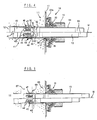
- the jacket pipe bushing or sealing arrangement shown in FIGS. 1 and 2 and constructed according to the invention has the structure described below.
- the wall opening 12 In the masonry 11 is the wall opening 12, which has been drilled in the usual way by means of suitable tools and through which the casing tube 13 is to be passed.
- the casing tube 13 can be made of plastic or steel and preferably has a thread 14 for the pressure nut 15 of the sealing arrangement 16.
- a fiber-reinforced bitumen plate 17 of sufficient dimensions is firmly and tightly glued.
- the bitumen plate 17 has a central circular cutout 18 the size of the wall opening 12.
- an annular disc 19 is placed coaxially to the hole 18, the hole reveal 20 of which is conical and which has at least one ring rib 21 which is pressed into the bitumen plate 17.
- the biconvex sealing body 22 made of permanently elastic material and having an inner or outer spherical surface 22a or 22b is seated on the casing tube 13. This sealing body 22 ensures a perfect seal of the wall duct, even if the casing tube 13 is not coaxially in the wall opening 12. Angular deviations that occur frequently during assembly are harmless, since the inner spherical surface 22a of the sealing body 22 is always in contact with the hole reveal 20 of the ring disk 19 over the entire area in the contact area.
- a sealing element 26 On the outer surface 22b of the sealing body 22 there is a sealing element 26 with a central dome-shaped part 27, which has a correspondingly large central opening 28 in order to be able to allow angular deviations.
- On the outside of the sealing element 26 On the outside of the sealing element 26 is the shape of the support disc 32, which has a central spherical part 33 and a peripheral annular part 34; the latter serves in particular to firmly press the sealing profile 30 of the sealing element 26 against the bitumen plate 17.
- the inner spherical end face of the nut 15 screwed onto the thread 14 of the casing tube 13 acts on the outer surface of the support disk 32, by means of which the entire sealing arrangement 16 is
- the diameters of the central openings in the annular disk 19 in the sealing element 26 and in the support disk 32 are at least about 10 to 30% larger than the diameter of the casing tube 13, in order to always ensure a perfect water- and gas-tight casing pipe bushing in the event of angular deviations of the pipe axis from the axis of the wall opening 12.
- FIGS. 4 and 5 show the fixing or anchoring of the casing tube piece 13 inserted into a wall opening 12 with its sealing device 16 arranged on the outside of the masonry 11, the masonry in FIG. 4 made of monolithic concrete and in FIG. 5 as a cavity Masonry.
- FIG. 4 In the upper half of FIG. 4, namely above the center line M, the arrangement for anchoring the tubular casing piece 13 to the surrounding masonry 11 is shown in a position after the tubular casing piece 13 has been inserted into the wall opening 12 with its inner end and before the assembly is unclamped in the axial direction to provide a proper water and gas tight seal.
- an axially tapering conical surface 42 which is surrounded by a spring steel collar 43, preferably made of stainless steel, which adjoins the conical surface 42 and projects axially inwards the circumference of the spring steel sleeve 43 has tabs 44 arranged in a uniformly distributed manner, the free ends of which are bent outwards to form a claw 45.
- a U-shaped cut 46 In each of the tabs 44 there is a U-shaped cut 46 to form spring tongues 47 projecting radially outwards and axially outwards.
- the outer end 53 of the casing tube 13 projecting outward from the wall opening 12 is provided with an external thread 54, onto which, for example, a ring nut 15, preferably a torque nut securing a predetermined and limited pressing force, is screwed, which the sealing device 16 against the masonry 11 presses.
- a ring nut 15 preferably a torque nut securing a predetermined and limited pressing force
- the sealing device essentially corresponds to that according to FIGS. 1 to 3, which has been described in detail above.
- the edge of the hole 56 is provided with a U-shaped profiled ring 57 made of sheet steel or another suitable material dressed, on which the sealing body 22 rests.
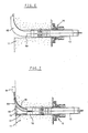
- this jacket tube piece 59 is provided with a bend 60 which has a radius of curvature such that the conductors in the or in the cable (s) are not damaged or bent in an impermissible manner.
- an insert 62 for example made of plastic, into the wall opening 12, which is widened in a radial plane at its inner end 61 and which, with its curved wall surface 63, provides a contact surface for the or forms the cable 65 to be inserted into a connection box 64 attached to the inner wall of the masonry 11, whereby the permissible curvature of the or the Cable is not exceeded.
- the inner opening of the insert 62 can be largely closed with a cover 66.
- the coupling arrangement designed according to the invention has also proven itself in particular in the case of wall openings 12 in masonry 11, which consists of bricks 68 containing cavities 67.
- the wall opening 12 penetrates the cavity 67, as a result of which the one contact surface 69 for the tongues 47 of the tabs 44 of the spring steel collar 43 is formed.
- the spring steel collar 43 is only prevented from further axial movement outwards by means of the tongues 47.
- FIG. 8 Another embodiment is shown in FIG. 8.
- the casing pipe 13 lying in the wall opening 12 is anchored by means of a pipe piece 71 which is connected to the casing pipe 13, for example screwed.
- the inner end 72 is provided with a thread 73 onto which the anchoring nut 74 is screwed with the interposition of an annular disk 75.
- the annular disk preferably has a spherical cap-shaped part 76 in its center, against which the nut 74 rests with its outer end in order to enable an angle compensation.
- In the tube 71 there is a cutout 77 from which the cables or tubes which are guided through the jacket tube 13 can be led out in a gentle curvature in order to avoid damaging sharp kinks.
Landscapes
- Engineering & Computer Science (AREA)
- General Engineering & Computer Science (AREA)
- Mechanical Engineering (AREA)
- Installation Of Indoor Wiring (AREA)
Applications Claiming Priority (4)
| Application Number | Priority Date | Filing Date | Title |
|---|---|---|---|
| DE3733237 | 1987-10-01 | ||
| DE19873733237 DE3733237A1 (de) | 1987-10-01 | 1987-10-01 | Mantelrohrdurchfuehrung durch das mauerwerk von haus- u. dgl. waenden |
| DE3803492 | 1988-02-05 | ||
| DE19883803492 DE3803492A1 (de) | 1988-02-05 | 1988-02-05 | Anordnung zum wasser- und gasdichten ankuppeln eines mantelrohrs an das mauerwerk von haus- u. dgl. waenden im bereich einer maueroeffnung |
Publications (2)
| Publication Number | Publication Date |
|---|---|
| EP0309836A2 true EP0309836A2 (fr) | 1989-04-05 |
| EP0309836A3 EP0309836A3 (fr) | 1991-03-20 |
Family
ID=25860403
Family Applications (1)
| Application Number | Title | Priority Date | Filing Date |
|---|---|---|---|
| EP19880115238 Withdrawn EP0309836A3 (fr) | 1987-10-01 | 1988-09-16 | Traversée étanche à l'eau et au gaz pour un tuyau ayant une enveloppe à travers de parois de maisons et autres choses semblables |
Country Status (1)
| Country | Link |
|---|---|
| EP (1) | EP0309836A3 (fr) |
Cited By (6)
| Publication number | Priority date | Publication date | Assignee | Title |
|---|---|---|---|---|
| DE4237478A1 (de) * | 1992-11-06 | 1994-01-27 | Eitle Rolf | Hauseinführung für Kabel |
| EP1580471A3 (fr) * | 2004-03-25 | 2009-07-29 | HL Hutterer & Lechner GmbH | Dispositif d'étanchéité |
| CN108518531A (zh) * | 2018-04-24 | 2018-09-11 | 安徽春辉仪表线缆集团有限公司 | 一种通用性高的用于从密闭容器中引出电缆的密封贯穿结构 |
| CN108963920A (zh) * | 2018-07-19 | 2018-12-07 | 芜湖籁余新能源科技有限公司 | 一种潜航器电缆贯穿耐压壳体的密封装置 |
| CN111146748A (zh) * | 2020-01-17 | 2020-05-12 | 浙江集弘电气有限公司 | 一种柱管式管口封堵装置及其使用方法 |
| CN115498571A (zh) * | 2022-09-21 | 2022-12-20 | 宁国市远大聚氨酯有限公司 | 一种穿墙线缆防渗密封结构及其施工方法 |
Family Cites Families (9)
| Publication number | Priority date | Publication date | Assignee | Title |
|---|---|---|---|---|
| DE869888C (de) * | 1938-10-13 | 1953-03-09 | Walther Mueller | Abdichtung an Rohren, Kabeln od. dgl. Leitungen bei Mauerdurchbruechen |
| DE1285800B (de) * | 1964-04-10 | 1968-12-19 | Rheinische Ziehglas Ag | Mauerdurchfuehrung fuer Installationsrohre mit einem gummielastischen Pressring zwischen dem Installationsrohr und einem Mauerschutzrohr |
| DE1684044C3 (de) * | 1965-10-21 | 1979-08-09 | Harold M. Ephrata Pa. Zimmerman (V.St.A.) | Fahrzeug mit Behältern zur Aufnahme von Betonkomponenten |
| DE1936772U (de) * | 1966-02-18 | 1966-04-14 | Georg Seiler | Mauerdurchfuhrung. |
| DE2203370A1 (de) * | 1972-01-25 | 1973-08-02 | Heinz Wunderlich | Vorrichtung zum verankern von rohrleitungsaustritten in der wand |
| US3814467A (en) * | 1972-04-17 | 1974-06-04 | Trw Inc | Connector for flexible conduit |
| JPS5343223A (en) * | 1976-09-30 | 1978-04-19 | Nippon Kokan Kk <Nkk> | Fitting structure of pipe body |
| DE8318034U1 (de) * | 1983-06-22 | 1983-11-03 | Schuck, Franz, 7920 Heidenheim | Hauseinfuehrungskombination zum einfuehren einer gasleitung in ein gebaeude |
| DE3623550C1 (en) * | 1986-07-12 | 1987-09-24 | Stewing Nachrichtentechnik | Device for sealing pipes, cables or similar tubular bodies which are led through wall openings |
-
1988
- 1988-09-16 EP EP19880115238 patent/EP0309836A3/fr not_active Withdrawn
Cited By (6)
| Publication number | Priority date | Publication date | Assignee | Title |
|---|---|---|---|---|
| DE4237478A1 (de) * | 1992-11-06 | 1994-01-27 | Eitle Rolf | Hauseinführung für Kabel |
| EP1580471A3 (fr) * | 2004-03-25 | 2009-07-29 | HL Hutterer & Lechner GmbH | Dispositif d'étanchéité |
| CN108518531A (zh) * | 2018-04-24 | 2018-09-11 | 安徽春辉仪表线缆集团有限公司 | 一种通用性高的用于从密闭容器中引出电缆的密封贯穿结构 |
| CN108963920A (zh) * | 2018-07-19 | 2018-12-07 | 芜湖籁余新能源科技有限公司 | 一种潜航器电缆贯穿耐压壳体的密封装置 |
| CN111146748A (zh) * | 2020-01-17 | 2020-05-12 | 浙江集弘电气有限公司 | 一种柱管式管口封堵装置及其使用方法 |
| CN115498571A (zh) * | 2022-09-21 | 2022-12-20 | 宁国市远大聚氨酯有限公司 | 一种穿墙线缆防渗密封结构及其施工方法 |
Also Published As
| Publication number | Publication date |
|---|---|
| EP0309836A3 (fr) | 1991-03-20 |
Similar Documents
| Publication | Publication Date | Title |
|---|---|---|
| EP2492569A2 (fr) | Liaison pour manchon | |
| DE3131690A1 (de) | "steckarmatur zum schnellen und loesbaren anschluss fuer kunststoff-rohrleitungen" | |
| EP0318019B1 (fr) | Dispositif pour la traversée de parois de bâtiments étanches au gaz et à l'eau par des objets longilignes | |
| EP0305723B1 (fr) | Traversée de mur pour câbles, conduites, tuyaux ou similaires | |
| EP0309836A2 (fr) | Traversée étanche à l'eau et au gaz pour un tuyau ayant une enveloppe à travers de parois de maisons et autres choses semblables | |
| DE2901266A1 (de) | Wanddurchfuehrung fuer kabel, leitungen, rohre o.dgl. | |
| EP0245233B1 (fr) | Pièce de raccordement, respectivement d'attache pour tuyaux et tuyaux flexibles | |
| DE3308877C2 (fr) | ||
| EP4661228A2 (fr) | Joint d'étanchéité pour tuyau unique | |
| DE3733237A1 (de) | Mantelrohrdurchfuehrung durch das mauerwerk von haus- u. dgl. waenden | |
| DE3803492A1 (de) | Anordnung zum wasser- und gasdichten ankuppeln eines mantelrohrs an das mauerwerk von haus- u. dgl. waenden im bereich einer maueroeffnung | |
| DE9312880U1 (de) | Kombinierte Schlauch- und Kabelverschraubung | |
| DE3938910C1 (en) | Plastic wall grommet-like arrangement for cabling - has outer threaded tube in bored hole fitted with flange section widened to funnel shape | |
| EP4279676B1 (fr) | Dispositif de raccordement à étanchéité améliorée sur un tube principal endommagé à l'intérieur | |
| DE102021103195B4 (de) | Verschlusshülse mit Klemmelement zum Abdichten einer Ankerspannstelle an einer Betonschalung | |
| DE102011085006A1 (de) | Vorrichtung zur Versorgung eines Gebäudes mit Wasser oder Gas | |
| DE4242236C1 (de) | Mauerdurchführung | |
| DE19634293C1 (de) | Gebäudeeinführung | |
| EP3738182A1 (fr) | Passe-câble à vis | |
| DE9310705U1 (de) | Vorrichtung zum Einbau von Rohren durch Wand- und Deckendurchbrüche, insbesondere von sogenannten Hauseinführungen | |
| DE19814982A1 (de) | Hauseinführung für Telekommunikationsleitungen | |
| EP0133455A2 (fr) | Dispositif de fermeture ou d'accouplement | |
| DE19602887C1 (de) | Verfahren und Bausatz zum Herstellen einer Leitungsverbindung | |
| EP0572823B1 (fr) | Traversée de mur | |
| DE3803494A1 (de) | Wasser- und gasdichte ankupplung eines mantelrohrs an das mauerwerk von haus- u. dgl. waenden im bereich einer oeffnung oder eines durchbruchs |
Legal Events
| Date | Code | Title | Description |
|---|---|---|---|
| PUAI | Public reference made under article 153(3) epc to a published international application that has entered the european phase |
Free format text: ORIGINAL CODE: 0009012 |
|
| AK | Designated contracting states |
Kind code of ref document: A2 Designated state(s): AT BE CH DE ES FR GB GR IT LI LU NL SE |
|
| PUAL | Search report despatched |
Free format text: ORIGINAL CODE: 0009013 |
|
| AK | Designated contracting states |
Kind code of ref document: A3 Designated state(s): AT BE CH DE ES FR GB GR IT LI LU NL SE |
|
| STAA | Information on the status of an ep patent application or granted ep patent |
Free format text: STATUS: THE APPLICATION IS DEEMED TO BE WITHDRAWN |
|
| 18D | Application deemed to be withdrawn |
Effective date: 19910921 |