EP0309924B1 - Gekapselte Gehäuse- und Deckelanordnung für Strombegrenzungsschalter - Google Patents
Gekapselte Gehäuse- und Deckelanordnung für Strombegrenzungsschalter Download PDFInfo
- Publication number
- EP0309924B1 EP0309924B1 EP88115602A EP88115602A EP0309924B1 EP 0309924 B1 EP0309924 B1 EP 0309924B1 EP 88115602 A EP88115602 A EP 88115602A EP 88115602 A EP88115602 A EP 88115602A EP 0309924 B1 EP0309924 B1 EP 0309924B1
- Authority
- EP
- European Patent Office
- Prior art keywords
- circuit breaker
- cover
- enclosure
- side walls
- projections
- Prior art date
- Legal status (The legal status is an assumption and is not a legal conclusion. Google has not performed a legal analysis and makes no representation as to the accuracy of the status listed.)
- Expired - Lifetime
Links
- 239000004033 plastic Substances 0.000 claims abstract description 5
- 239000002184 metal Substances 0.000 claims description 7
- 239000002991 molded plastic Substances 0.000 claims description 6
- 239000000463 material Substances 0.000 claims description 4
- 238000004519 manufacturing process Methods 0.000 claims description 3
- 230000003014 reinforcing effect Effects 0.000 claims description 3
- 230000000295 complement effect Effects 0.000 abstract description 3
- 239000007789 gas Substances 0.000 description 22
- 238000000034 method Methods 0.000 description 6
- 238000013022 venting Methods 0.000 description 2
- 230000009286 beneficial effect Effects 0.000 description 1
- 230000008033 biological extinction Effects 0.000 description 1
- 230000005540 biological transmission Effects 0.000 description 1
- 239000002131 composite material Substances 0.000 description 1
- 238000003780 insertion Methods 0.000 description 1
- 230000037431 insertion Effects 0.000 description 1
- 238000000465 moulding Methods 0.000 description 1
Images


Classifications
-
- H—ELECTRICITY
- H01—ELECTRIC ELEMENTS
- H01H—ELECTRIC SWITCHES; RELAYS; SELECTORS; EMERGENCY PROTECTIVE DEVICES
- H01H71/00—Details of the protective switches or relays covered by groups H01H73/00 - H01H83/00
- H01H71/02—Housings; Casings; Bases; Mountings
- H01H71/025—Constructional details of housings or casings not concerning the mounting or assembly of the different internal parts
- H01H71/0257—Strength considerations
Definitions
- This invention relates to a unique insulating enclosure for low voltage current limiting circuit breakers and, more specifically, to the inter-connection between the case and the cover of the enclosure to allow the enclosure to strongly resist the overpressure caused by gases generated during the interruption process.
- the standard insulating molded plastic enclosure for such low voltage circuit breakers consists of an enclosure, which contains the circuit breakers components, provided with a cover having openings for an operating handle.
- the cover is usually attached to the case by screws passing through the cover itself to engage threaded openings in the case. Additionally, the cover includes projecting ridges for accurate alignment with the case.
- the high gas pressure generated when a short circuit occurs, exerts a strong mechanical stress to the side walls of the case which ordinarily is incapable of resisting such a high pressure. Accordingly, it is considered beneficial to transfer such a stress from the side walls of the case to the cover which is more capable of resisting stress because of the reduced height and increased thickness thereof.
- Another know method of reinforcing the enclosure consisted of providing a number of metal pins in the edge of the cover received whithin corresponding recesses formed in the cross-section of the side walls of the case. The method was effective for increasing the resistance of the enclosure to stress but resulted in an increase in the overall cost of manufacturing the cover and the case.
- FR-A-2 386 899 discloses a method for connecting, by means of tenons and mortises members of a composite socket having the purpose of housing electric devices such as relays and circuit breakers, but cannot suggest the transmission of stresses due to gas pressures from a member to another one. Furhter the tenons and the mortises are each other coupled in the tightest way the possible so that such a couplement cannot suggest in any way to vent the gas developped in a circuit breaker.
- the invention regards a circuit breaker enclosure comprising a molded plastic case and a molded plastic cover in which said cover includes a pair of opposing side walls having a plurality of dovetail projections extending therefrom and said case includes a pair of side walls having a corresponding plurality of recesses formed therein, said recesses being shaped to accept said dovetail projections, wherein said dovetail projections each comprise a pair of opposing internal and external surfaces, said external surfaces being larger than said internal surfaces and wherein said opposing internal and external surfaces are joined by tapering edges, said edges tapering inwards from said external surfaces to said internal surfaces.
- said recesses are flanked by intermediate projections having internal and external surfaces, said intermediate projections having tapering side walls and said side walls taper outwards from said internal to said external surfaces.
- a further embodiment includes a metal tang embedded within the dovetails projections on the cover to provide increased stiffness to the dovetail projections.
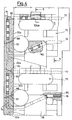
- the molded plastic insulating enclosure 10 shown in Figure 1 is designed for a current limiting circuit breaker, according to the invention and consists of a case 12 which houses the components of the low voltage circuit breaker (not shown) and a cover 14.
- the case includes two side walls 16 and 18 which occur upon short circuit interruption whereby the gases developed in the arc chambers of the circuit breaker generate such a high internal pressure that side walls would otherwise camber and move away from each other.
- the upper edges of the side walls 16 and 18 have, at both ends, areas defined at 23, 24, 26 and 28 respectively which are separated by recesses 20a, 20b, 20c, 20d, 20e, 20f, 20g and 20h, alternated with outwardly tapered protrusions 22a, 22b, 22c, 22e, 22f and 22g.
- Each of the protrusions is defined by a narrow exterior surface and a wider interior surface.
- the cover is provided with a pair of opposing side walls 30A, 30B.
- a plurality of dovetail-shaped projections 32a, 32b, 32c, 32d alternate with recesses 34a, 34b, 34c which reciprocally align with the protusions 22a-d of the corresponding side wall 16 as best seen by referring to Figure 2.
- a pair of thru-holes 36 and 38 on one end of the cover 14 aligns with the corresponding threaded holes 44 and 46 in the case 12, for attaching the cover to that side of the case 12.
- a similar pair of thru-holes 52 and 54 on the opposite side of the cover aligns with a corresponding pair of threaded holes 64 and 66 in the case for attaching the opposite end of the cover to the case as shown in Figure 1.
- the remaining thru-holes 40, 42, 56 and 58 in the cover respectively align with corresponding thru-holes 48, 50, 60 and 62 in the case to allow for attaching the circuit breaker within a panelboard.
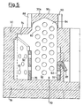
- Such additional support consists of a U-shaped sheet metal bracket 70 embedded in the top and side walls of the cover itself.
- the U-shaped bracket includes a first leg 72, exending from the interior to the exterior of the cover, a bight 74 and second leg 76 extending from the exterior to the interior of the cover.
- the legs 72, 76, and bight 74 are embedded in the molded top part of the cover 14 so that the entire braket 70 is embedded in the insulating plastic material forming the cover as indicated at 80.
- a plurality of holes 82 are formed in the metal sheet of the bracket.
- the holes become filled with the plastic material 80 during the molding process.
- a tail piece or tang 84 protrudes from yoke or bight 74 of the bracket 70 which extends into the protrusions of the lateral wall of the cover to enhance the strength of the dovetail projections as depicted at 32a in Figure 5.
- the dovetail projections such as 32a, 32b in Figure 4 are provided with tapered edges 88, 90 which complement corresponding tapered edges 92, 94 and the recesses 20a-d in the side walls of the case 12.
- the gaps between the tops 96 of the dovetail 32a-d of the cover 14 and the bottoms 98 of the recesses 20a-d of the case 12 permit a limited amount of gas venting from the enclosure 10.
- the U-shaped brackets receive the gas pressure through the tail piece 84 when embedded in the body of the dovetail projections and transfer the gas pressure to the top 78 of the cover by means of legs 72 and 76. As depicted in figure 5, the operation of the bracket 70 is insured by an accurate positioning of the tang 84 inside the body of the dovetail projection 32a.
- This positioning is obtained by using the folded tang 87 as a reference point which, in turn, allows the bracket 70 to be positioned within the mold during the manufacturing of the cover 14 itself.
Landscapes
- Switch Cases, Indication, And Locking (AREA)
- Breakers (AREA)
- Casings For Electric Apparatus (AREA)
- Distribution Board (AREA)
- Fuses (AREA)
- Motor Or Generator Frames (AREA)
Claims (10)
- Gehäuse für einen Strombegrenzungsschalter, der ein Formoberteil (14) aus Kunststoff und ein Formunterteil (12) aus Kunststoff aufweist, wobei das Oberteil (14) zwei gegenüberliegende Seitenwände (30A, 30B) mit mehreren davon ausgehenden schwalbenschwanzförmigen Vorsprüngen (32a-d) aufweist und das Unterteil (12) zwei Seitenwände (16, 18) aufweist, in denen eine entsprechende Anzahl von Aussparungen (20a-h) ausgebildet sind, wobei die Aussparungen (20a-h) zur Aufnahme der schwalbenschwanzförmigen Vorsprünge (32a-d) ausgebildet sind, die jeweils ein Paar gegenüberliegender interner und externer Oberflächen aufweisen, wobei die externen Oberflächen größer sind als die internen Oberflächen und die gegenüberliegenden internen und externen Oberflächen durch schräge Ränder (88, 90) miteinander verbunden sind, die von den externen Oberflächen zu den internen Oberflächen schräg nach innen verlaufen.
- Schaltergehäuse nach Anspruch 1, dadurch gekennzeichnet, daß die Aussparungen (20a-h) von Zwischenvorsprüngen (22a-g) flankiert sind, die interne und externe Oberflächen und schräge Seitenwände (92, 94) aufweisen, die von den internen zu den externen Oberflächen schräg nach außen verlaufen.
- Schaltergehäuse nach Anspruch 2, wobei die schwalbenschwanzförmigen Vorsprünge (32a-d) in den Aussparungen (20a-h) sitzen, dadurch gekennzeichnet, daß die schrägen Ränder (88, 90) auf den schwalbenschwanzförmigen Vorsprüngen (32a-d) an den schrägen Rändern (92, 94) auf den Zwischenvorsprüngen (22a-g) anliegen.
- Schaltergehäuse nach Anspruch 1, dadurch gekennzeichnet, daß metallische Verstärkungsmittel (70) in den schwalbenschwanzförmigen Vorsprüngen (32a-d) vorgesehen sind.
- Schaltergehäuse nach Anspruch 4, dadurch gekennzeichnet, daß die metallischen Verrstärkungsmittel (70) eine U-Form besitzen.
- Schaltergehäuse nach Anspruch 5, dadurch gekennzeichnet, daß die U-Form zwei planare Seitenschenkel (72, 76) aufweist, die durch einen planaren Buchtteil (74) verbunden sind.
- Schaltergehäuse nach Anspruch 6, dadurch gekennzeichnet, daß ein Schaft (84) von dem Buchtteil (74) ausgeht und in einen der schwalbenschwanzförmigen Vorsprünge (32a-d) vorsteht.
- Schaltergehäuse nach Anspruch 5, dadurch gekennzeichnet, daß die U-Form mehrere Löcher (82) bildet zur Aufnahme von Kunststoffmaterial während der Fertigung des Oberteils (14).
- Schaltergehäuse nach Anspruch 8, dadurch gekennzeichnet, daß ein Schaft (87) von der U-Form ausgeht zur Positionierung der U-Form in dem Oberteil.
- Schaltergehäuse nach Anspruch 3, dadurch gekennzeichnet, daß ein Boden von Jedem der schwalbenschwanzförmigen Vorsprünge (32a-d) und ein Boden von Jeder der Aussparungen (20a-h) einen vorbestimmten Spalt dazwischen bilden, der den Durchtritt von Gas aus einem Innenraum zu einem Außenraum des Gehäuses gestattet.
Applications Claiming Priority (2)
| Application Number | Priority Date | Filing Date | Title |
|---|---|---|---|
| IT2245287U | 1987-09-29 | ||
| IT8722452U IT211844Z2 (it) | 1987-09-29 | 1987-09-29 | Accoppiamento tra base e coperchio di un interruttore in scatola isolante stampata particolarmente resistente a deformazioni e rotture dovute a sovrappressioni derivate da gas prodotti da archi o simili. |
Publications (3)
| Publication Number | Publication Date |
|---|---|
| EP0309924A2 EP0309924A2 (de) | 1989-04-05 |
| EP0309924A3 EP0309924A3 (en) | 1990-06-13 |
| EP0309924B1 true EP0309924B1 (de) | 1994-07-20 |
Family
ID=11196492
Family Applications (1)
| Application Number | Title | Priority Date | Filing Date |
|---|---|---|---|
| EP88115602A Expired - Lifetime EP0309924B1 (de) | 1987-09-29 | 1988-09-22 | Gekapselte Gehäuse- und Deckelanordnung für Strombegrenzungsschalter |
Country Status (4)
| Country | Link |
|---|---|
| EP (1) | EP0309924B1 (de) |
| AT (1) | ATE108944T1 (de) |
| DE (1) | DE3850732T2 (de) |
| IT (1) | IT211844Z2 (de) |
Families Citing this family (3)
| Publication number | Priority date | Publication date | Assignee | Title |
|---|---|---|---|---|
| US4860162A (en) * | 1988-09-29 | 1989-08-22 | General Electric Company | Molded case and cover arrangement for current limiting circuit interrupters |
| DE19958945A1 (de) | 1999-11-26 | 2001-05-31 | Siemens Ag | Elektrisches Schaltgerät mit mehreren Gehäuseteilen |
| US20230377822A1 (en) * | 2022-05-20 | 2023-11-23 | Rockwell Automation Technologies, Inc. | Circuit breaker housing with two-stage structure |
Family Cites Families (5)
| Publication number | Priority date | Publication date | Assignee | Title |
|---|---|---|---|---|
| GB530353A (en) * | 1939-06-22 | 1940-12-10 | Crabtree & Co Ltd J A | Improvements in, and connected with, boxes or covers for electrical apparatus |
| US3632939A (en) * | 1970-02-16 | 1972-01-04 | Westinghouse Electric Corp | Circuit interrupter with improved molded insulating housing |
| DE7711221U1 (de) * | 1977-04-09 | 1977-08-18 | Ellenberger & Poensgen Gmbh, 8503 Altdorf | Klemmbrett für elektrische Installationsgeräte |
| DE2802553B1 (de) * | 1978-01-19 | 1979-01-18 | Siemens Ag | Niederspannungs-Leistungsschalter mit geteiltem Isolierstoffgehaeuse |
| IT210417Z2 (it) * | 1987-06-09 | 1988-12-30 | Bassani Spa | Apparecchiatura elettrica di protezione magnetermica e differenziale. |
-
1987
- 1987-09-29 IT IT8722452U patent/IT211844Z2/it active
-
1988
- 1988-09-22 AT AT88115602T patent/ATE108944T1/de not_active IP Right Cessation
- 1988-09-22 DE DE3850732T patent/DE3850732T2/de not_active Expired - Fee Related
- 1988-09-22 EP EP88115602A patent/EP0309924B1/de not_active Expired - Lifetime
Also Published As
| Publication number | Publication date |
|---|---|
| ATE108944T1 (de) | 1994-08-15 |
| DE3850732T2 (de) | 1995-03-16 |
| IT8722452V0 (it) | 1987-09-29 |
| IT211844Z2 (it) | 1989-05-25 |
| DE3850732D1 (de) | 1994-08-25 |
| EP0309924A3 (en) | 1990-06-13 |
| EP0309924A2 (de) | 1989-04-05 |
Similar Documents
| Publication | Publication Date | Title |
|---|---|---|
| EP1464063B1 (de) | Elektrischer pol für einen niederspannungsschutzschalter und dazugehoeriger niederspannungsschutzschalter | |
| EP1213741B1 (de) | Schmelzsicherungsdose | |
| EP1454331B1 (de) | Kontaktarme tragende schaltwelle für einen niederspannungsschutzschalter | |
| EP0353950B1 (de) | Gummianschläge in Aussenpolen | |
| EP0353940B1 (de) | Querbalkenanordnung | |
| EP0422868B1 (de) | Anordnung zum schnellen Austauschen eines Stromtransformators und Kraftübertragungsabstandhalter | |
| US4860162A (en) | Molded case and cover arrangement for current limiting circuit interrupters | |
| EP0309924B1 (de) | Gekapselte Gehäuse- und Deckelanordnung für Strombegrenzungsschalter | |
| US5686709A (en) | Modular trip bar assembly for multipole circuit breaker | |
| US3840717A (en) | Manually operated rotary switch and combination load contact-fuse clip therefor | |
| AU623409B2 (en) | A molded case circuit breaker with an unriveted upper link securement | |
| EP0353939B1 (de) | Methode zum schnellen Austauschen eines Stromtransformators | |
| US6005207A (en) | Multi-part circuit breaker housing | |
| EP0353951A2 (de) | Kombinationssperre und Hilfsstromtransformatorplatte | |
| AU621906B2 (en) | A circuit breaker with a modular option deck | |
| JP2001160349A (ja) | 2極回路遮断器 | |
| IE73215B1 (en) | Crossbar assembly | |
| JPH083950Y2 (ja) | 回路しや断器の筐体 | |
| KR200229098Y1 (ko) | 진공차단기의 대차 | |
| KR820002264Y1 (ko) | 다극 저전압 회로차단기 | |
| WO1997028546A1 (fr) | Disjoncteur | |
| EP0691029A1 (de) | Einheitsschaltermodul für mehrpoligen motor lastschalter und motorlastschalter mit solchem einheitsmodul ausgestattet |
Legal Events
| Date | Code | Title | Description |
|---|---|---|---|
| PUAI | Public reference made under article 153(3) epc to a published international application that has entered the european phase |
Free format text: ORIGINAL CODE: 0009012 |
|
| AK | Designated contracting states |
Kind code of ref document: A2 Designated state(s): AT BE CH DE FR GB IT LI NL SE |
|
| PUAL | Search report despatched |
Free format text: ORIGINAL CODE: 0009013 |
|
| AK | Designated contracting states |
Kind code of ref document: A3 Designated state(s): AT BE CH DE FR GB IT LI NL SE |
|
| RHK1 | Main classification (correction) |
Ipc: H01H 71/02 |
|
| 17P | Request for examination filed |
Effective date: 19901114 |
|
| 17Q | First examination report despatched |
Effective date: 19930616 |
|
| GRAA | (expected) grant |
Free format text: ORIGINAL CODE: 0009210 |
|
| AK | Designated contracting states |
Kind code of ref document: B1 Designated state(s): AT BE CH DE FR GB IT LI NL SE |
|
| PG25 | Lapsed in a contracting state [announced via postgrant information from national office to epo] |
Ref country code: NL Effective date: 19940720 Ref country code: LI Effective date: 19940720 Ref country code: CH Effective date: 19940720 Ref country code: BE Effective date: 19940720 Ref country code: AT Effective date: 19940720 |
|
| REF | Corresponds to: |
Ref document number: 108944 Country of ref document: AT Date of ref document: 19940815 Kind code of ref document: T |
|
| REF | Corresponds to: |
Ref document number: 3850732 Country of ref document: DE Date of ref document: 19940825 |
|
| ITF | It: translation for a ep patent filed | ||
| PG25 | Lapsed in a contracting state [announced via postgrant information from national office to epo] |
Ref country code: SE Effective date: 19941020 Ref country code: GB Effective date: 19941020 |
|
| REG | Reference to a national code |
Ref country code: CH Ref legal event code: PL |
|
| ET | Fr: translation filed | ||
| NLV1 | Nl: lapsed or annulled due to failure to fulfill the requirements of art. 29p and 29m of the patents act | ||
| PLBE | No opposition filed within time limit |
Free format text: ORIGINAL CODE: 0009261 |
|
| STAA | Information on the status of an ep patent application or granted ep patent |
Free format text: STATUS: NO OPPOSITION FILED WITHIN TIME LIMIT |
|
| GBPC | Gb: european patent ceased through non-payment of renewal fee |
Effective date: 19941020 |
|
| 26N | No opposition filed | ||
| PGFP | Annual fee paid to national office [announced via postgrant information from national office to epo] |
Ref country code: DE Payment date: 20031128 Year of fee payment: 16 |
|
| PGFP | Annual fee paid to national office [announced via postgrant information from national office to epo] |
Ref country code: FR Payment date: 20031230 Year of fee payment: 16 |
|
| PG25 | Lapsed in a contracting state [announced via postgrant information from national office to epo] |
Ref country code: DE Free format text: LAPSE BECAUSE OF NON-PAYMENT OF DUE FEES Effective date: 20050401 |
|
| PG25 | Lapsed in a contracting state [announced via postgrant information from national office to epo] |
Ref country code: FR Free format text: LAPSE BECAUSE OF NON-PAYMENT OF DUE FEES Effective date: 20050531 |
|
| REG | Reference to a national code |
Ref country code: FR Ref legal event code: ST |
|
| PG25 | Lapsed in a contracting state [announced via postgrant information from national office to epo] |
Ref country code: IT Free format text: LAPSE BECAUSE OF NON-PAYMENT OF DUE FEES;WARNING: LAPSES OF ITALIAN PATENTS WITH EFFECTIVE DATE BEFORE 2007 MAY HAVE OCCURRED AT ANY TIME BEFORE 2007. THE CORRECT EFFECTIVE DATE MAY BE DIFFERENT FROM THE ONE RECORDED. Effective date: 20050922 |