EP0309970A2 - Dispositif d'accouplement pour fers d'armature - Google Patents
Dispositif d'accouplement pour fers d'armature Download PDFInfo
- Publication number
- EP0309970A2 EP0309970A2 EP88115843A EP88115843A EP0309970A2 EP 0309970 A2 EP0309970 A2 EP 0309970A2 EP 88115843 A EP88115843 A EP 88115843A EP 88115843 A EP88115843 A EP 88115843A EP 0309970 A2 EP0309970 A2 EP 0309970A2
- Authority
- EP
- European Patent Office
- Prior art keywords
- insert
- sleeve
- threads
- coupler
- tapered
- Prior art date
- Legal status (The legal status is an assumption and is not a legal conclusion. Google has not performed a legal analysis and makes no representation as to the accuracy of the status listed.)
- Withdrawn
Links
- 230000003014 reinforcing effect Effects 0.000 title claims abstract description 15
- 239000004567 concrete Substances 0.000 claims abstract description 12
- 230000009471 action Effects 0.000 claims abstract description 3
- 230000004323 axial length Effects 0.000 claims description 4
- 238000010276 construction Methods 0.000 abstract description 8
- 230000008878 coupling Effects 0.000 description 7
- 238000010168 coupling process Methods 0.000 description 7
- 238000005859 coupling reaction Methods 0.000 description 7
- 239000011178 precast concrete Substances 0.000 description 4
- 230000004075 alteration Effects 0.000 description 2
- 238000009434 installation Methods 0.000 description 2
- 230000004048 modification Effects 0.000 description 2
- 238000012986 modification Methods 0.000 description 2
- 230000007704 transition Effects 0.000 description 2
- 230000009286 beneficial effect Effects 0.000 description 1
- 230000015572 biosynthetic process Effects 0.000 description 1
- 238000005266 casting Methods 0.000 description 1
- 230000001934 delay Effects 0.000 description 1
Images


Classifications
-
- E—FIXED CONSTRUCTIONS
- E04—BUILDING
- E04C—STRUCTURAL ELEMENTS; BUILDING MATERIALS
- E04C5/00—Reinforcing elements, e.g. for concrete; Auxiliary elements therefor
- E04C5/16—Auxiliary parts for reinforcements, e.g. connectors, spacers, stirrups
- E04C5/162—Connectors or means for connecting parts for reinforcements
- E04C5/163—Connectors or means for connecting parts for reinforcements the reinforcements running in one single direction
- E04C5/165—Coaxial connection by means of sleeves
-
- Y—GENERAL TAGGING OF NEW TECHNOLOGICAL DEVELOPMENTS; GENERAL TAGGING OF CROSS-SECTIONAL TECHNOLOGIES SPANNING OVER SEVERAL SECTIONS OF THE IPC; TECHNICAL SUBJECTS COVERED BY FORMER USPC CROSS-REFERENCE ART COLLECTIONS [XRACs] AND DIGESTS
- Y10—TECHNICAL SUBJECTS COVERED BY FORMER USPC
- Y10T—TECHNICAL SUBJECTS COVERED BY FORMER US CLASSIFICATION
- Y10T403/00—Joints and connections
- Y10T403/57—Distinct end coupler
- Y10T403/5733—Plural opposed sockets
-
- Y—GENERAL TAGGING OF NEW TECHNOLOGICAL DEVELOPMENTS; GENERAL TAGGING OF CROSS-SECTIONAL TECHNOLOGIES SPANNING OVER SEVERAL SECTIONS OF THE IPC; TECHNICAL SUBJECTS COVERED BY FORMER USPC CROSS-REFERENCE ART COLLECTIONS [XRACs] AND DIGESTS
- Y10—TECHNICAL SUBJECTS COVERED BY FORMER USPC
- Y10T—TECHNICAL SUBJECTS COVERED BY FORMER US CLASSIFICATION
- Y10T403/00—Joints and connections
- Y10T403/57—Distinct end coupler
- Y10T403/5793—Distinct end coupler including member wedging or camming means
Definitions
- This invention relates generally as indicated to a reinforcing bar coupler and more particularly to a position coupler for connecting reinforcing bar in concrete construction where neither of the bars joined need be rotated.
- couplers known as position couplers are employed.
- Such couplers normally comprise separate threaded couplers for each bar end and a linking sleeve which engages the respective bar couplers.
- Such couplers may also be used with opposite hand threads to act as turnbuckles which when tightened draw the bar ends together. Examples of several forms of position couplers may be seen in U.S. Patent No. 3,850,535.
- a conventional position coupler such as that manufactured by Erico Products, Inc. of Solon, Ohio under such trademark LENTON includes a long female internally cylindrically threaded end member and a male externally cylindrically threaded connector end member, both of which are taper thread connected to the joined ends of reinforcing bar.
- a jam or lock nut is positioned on the threads of the male connector end and must be tightened against the female long end after the male and female ends are properly secured and tightened on the respective bars.
- Position couplers While quite adequate for the intended purpose, present some field installation problems.
- the male and female ends are of course rotated in the opposite directions for tightening and when the jam nut is tightened it is rotated on the cylindrical threads of the connecter end in a direction which may tend to loosen the connector end taper threaded connection to its bar.
- Position couplers normally require torquing of at least some of the parts in opposite directions. If rotational slippage occurs, the connector end may require retightening and/or being held by a second wrench during the tightening of the jam nut. Since the field installation of such position couplers is not like working at a bench with a vise, a slippage problem can reduce the productivity of the installer.
- flank contact In machined thread couplers, because of imperfect thread flank contact, when the coupling is placed under tension some axial slippage also may occur. Thus if flank contact can be improved when the coupling is formed, such axial slippage can be minimized.
- a position coupler for connecting reinforcing bar in concrete construction where neither bar is able to rotate either conveniently or not at all includes a sleeve at least a portion of which is internally cylindrically threaded and which received at least one split collar insert.
- the insert has external cylindrical threads which match the internal cylindrical threads of the sleeve and also has internal tapered threads which match the tapered external threads on the bars to be joined.
- the inserts, in addition to being longitudinally split are provided with either a transverse slot or a hex head on their outer ends to receive a wrench. When a transverse slot is provided a spanner wrench may be inserted between the bar and sleeve.
- the tightening of the insert creates a wedge action which hoop stresses the sleeve locking the parts together and reduces slippage.
- the insert may be locked anywhere along the interior of the cylindrical thread portion of the sleeve to connect bars at different axial spacings.
- the sleeve is machined from stock with the cylindrical threads receiving the insert being formed on one end while the opposite end is provided with a taper thread socket having taper threads which match the external tapered threads of the bars to be joined.
- the sleeve is formed of tube with the internal cylindrical threads extending the length of the sleeve and an insert for each bar is employed. The sleeve may be provided with opposite hand threads so that rotation of the sleeve will draw the rods together before the inserts are fully torqued and locked.
- FIG. 1 there is illustrated a position coupler in accordance with the present invention shown generally at 15 which includes a sleeve shown generally at 17 and a threaded collar insert shown generally at 18.
- the sleeve 17 may be circularly cylindrical or include a hexagonal outer configuration for the application of a wrench and at one end includes a taper threaded socket 20.
- the sleeve includes a cylindrical threaded socket 22 which is somewhat axially longer than the taper threaded socket.
- the blind end of the taper thread socket indicated at 23 is unthreaded and slightly spaced from the blind end 24 of the socket 22 forming a wall 25.
- the unthreaded portion 23 may of course be omitted.
- the insert 18 shown in more detail in Figures 3 and 4 is cylindrical in configuration and includes external cylindrical threads 27 which match the internal cylindrical threads 28 of the socket 22.
- the insert has an axial length substantially shorter than the axial length of the socket 22.
- the interior of the insert includes a taper thread section 30 which has tapered threads 31 which may be the same as the tapered threads of socket 20. If the position coupler is also a transition coupler the tapered threads of the insert may be of a different size matching the bar to be joined.
- the enlarged end of the tapered thread section terminates at the outer end face 33 of the collar insert while the inner or narrow end terminates at the end of smaller diameter cylindrical hole 34.
- the cylindrical hole continues to the inner end face 35 of the insert.
- the collar insert is longitudinally slit along one side as indicated by the slot 37.
- the outer end face is provided with diametral face slot sections 39 and 40.
- the slots 39 and 40 in the outer end face of the insert are adapted to receive the fingers 47 and 48 of a spanner wrench 49 shown generally in Figures 8 and 9.
- the fingers 47 and 48 project axially from one end 50 of semi-cylindrical body 51 and handle 52 projects radially from the other end 53.
- the spanner wrench may be inserted in the interior of socket 22 surrounding the bar 43 with the fingers 47 and 48 engaging the diametral slots 39 and 40 of the collar insert so that the collar insert may be turned with respect to both the sleeve 17 and bar 43.
- other types of spanner wrenches may be employed including those of the ratchet type and also those which indicate torque loading.
- the joint shown in Figure 2 may be formed by first tightening the sleeve 17 on the bar 42 and then rotating the insert with the spanner wrench, in a direction to unscrew it from the socket 22, which then tightens the internal threads of the insert on the threaded section of the bar 43. In this manner neither bar is required to rotate.
- the tightening of the insert causes the insert to expand slightly creating hoop stresses in the cylindrical threaded section of the sleeve locking the sleeve, insert and bar together. This of course minimizes axial slip when the joint is under tension.
- the embodiment of Figures 1-4 comprises but two parts, namely the sleeve and one assembled collar insert.
- the position coupler 56 of Figure 5 comprises three parts which are an elongated seamless internally threaded sleeve 57 and split collar inserts 58 and 59 for respective taper threaded bars 60 and 61.
- the split collar inserts 58 and 59 may be identical each having external cylindrical threads matching the internal cylindrical threads 63 in the sleeve, and each having internal tapered threads matching the tapered thread end sections 64 and 65 on the respective rods.
- the outer ends of each insert are also provided with the diametral slots seen at 66 and 67 for engagement by the spanner wrench.
- the sleeve 57 may also have a hexagonal exterior configuration.
- the threads 63 on the interior of the sleeve 57 may be all of one hand with the threads on the exterior of the collar inserts being matching.
- the inserts are threaded into the sleeve at the desired location.
- the insert is rotated in a counterclockwise direction facing the lefthand end of the sleeve in Figure 5. This assembles the insert on the rod 60.
- the position of the insert in the sleeve may be adjusted by rotating the sleeve with respect to the insert. At insert may be turned with respect to both the sleeve 17 and bar 43.
- the joint shown in Figure 2 may be formed by first tightening the sleeve 17 on the bar 42 and then rotating the insert with the spanner wrench, in a direction to unscrew it from the socket 22, which then tightens the internal threads of the insert on the threaded section of the bar 43. In this manner neither bar is required to rotate.
- the tightening of the insert causes the insert to expand slightly creating hoop stresses in the cylindrical threaded section of the sleeve locking the sleeve, insert and bar together. This of course minimizes axial slip when the joint is under tension.
- the embodiment of Figures 1-4 comprises but two parts, namely the sleeve and one assembled collar insert.
- the position coupler 56 of Figure 5 comprises three parts which are an elongated seamless internally threaded sleeve 57 and split collar inserts 58 and 59 for respective taper threaded bars 60 and 61.
- the split collar inserts 58 and 59 may be identical each having external cylindrical threads matching the internal cylindrical threads 63 in the sleeve, and each having internal tapered threads matching the tapered thread end sections 64 and 65 on the respective rods.
- the outer ends of each insert are also provided with the diametral slots seen at 66 and 67 for engagement by the spanner wrench.
- the sleeve 57 may also have a hexagonal exterior configuration.
- the threads 63 on the interior of the sleeve 57 may be all of one hand with the threads on the exterior of the collar inserts being matching.
- the inserts are threaded into the sleeve at the desired location.
- the insert is rotated ina counterclockwise direction facing the lefthand end of the sleeve in Figure 5.
- This assembles the insert on the rod 60.
- the position of the insert in the sleeve may be adjusted by rotating the sleeve with respect to the insert.
- the insert may then be fully torqued and because of its ability slightly to expand the insert sleeve and bar 60 will be locked together.
- the sleeve will of course be hoop stressed in the area of the insert 58.
- the insert 59 may then be assembled on the rod 61 by rotating the insert 59 in a counterclockwise direction as viewed from the righthand end of the sleeve in Figure 5. Because of the nature of the inserts, when the insert 59 is fully torqued, any tendency of the sleeve to rotate will be minimized. Also, when fully torqued better thread flank engagement is achieved which minimizes any axial slip tendency under tensile load.
- sleeve 70 which may have a cylindrical or hexagonal external configuration and which is internally threaded with opposite hand threads as indicated at 71 and 72.
- the opposite hand threads extend for half the length of the sleeve.
- Inserts 73 and 74 of the same split and notched construction as the inserts 58 and 59 are threaded on the tapered thread sections 76 and 77 on the ends of respective reinforcing bars 78 and 79.
- Such inserts have external threads matching the opposite hand threads of the sleeve.
- the sleeve 70 may be rotated with respect to the inserts to draw the two bars 78 and 79 toward each other, or for that matter to move them apart. When the desired spacing is obtained the inserts are fully torqued locking the parts together.
- FIG. 11 there are illustrated various applications for position couplers in accordance with the present invention.
- two precast or cast concrete elements illustrated at 80 and 81 which include opposed projecting reinforcing or dowel rods 82, 83, 84 and 85, each of which includes a taper thread end section.
- the rod 82 projecting from the element 80 extends further than the rod 84 so that the spacing between the rods 82 and 83 is less than the spacing between the rods 84 and 85. Regardless of such spacing differential, the rods can be joined with the position couplers of the present invention.
- FIG 12 there is illustrated a typical column cage wherein the position couplers or joints of the present invention are employed to join the vertically extending reinforcing rod of top and bottom cage sections 90 and 91.
- the vertically extending rods of such cages indicated generally at 93 are normally wire tied to rod 94 and thus the rods 93 in the sections cannot normally be rotated after the cage sections are formed. Also, the axial spacing of the rods may not in each instance be the same. In any event the joining of rods in cage sections presents an ideal application for the position coupler of the present invention.
- FIG. 13 With reference to Figure 13 and 14 there is illustrated a position coupler in accordance with the present invention used as a connection socket in the formation of a pour or a precast concrete element.
- the position coupler sleeve 17 is threaded on taper threaded end section 44 of rod 42 and tightened.
- the insert 18 is assembled in the cylindrical thread socket 22 and a cap 96 having a few external threads 97 on a short projecting stud is threaded in the end of the socket compressing O-ring seal 98.
- the seal keeps concrete out of the socket when the concrete is poured.
- the end cap is abutted against form 99 and the concrete 100 is poured. When the form 99 is removed the end cap is exposed.
- the insert may then be used to attach a rod to the position coupler in a continuing pour.
- the position coupler forms a recessed rod or dowell attachment connection. In this manner disassembly of the insert is not required.
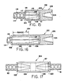
- position couplers in accordance with the present invention can be formed with split collar inserts which include an axially extending radially projecting hexagonal or flatted head so that the insert can be turned with a more conventional wrench rather than a spanner wrench as seen in Figures 8 and 9.
- the position coupler shown generally at 102 includes a sleeve 103 which may be essentially the same as the sleeve 17 of Figure 1.
- the sleeve includes at one end a taper internally threaded socket 104 to receive the taper externally threaded end of a reinforcing bar (not shown) in the same manner as in Figure 2.
- the opposite end of the sleeve is provided with an internally cylindrically threaded socket 105 which receives split collar insert 106.
- the insert is provided with external cylindrical threads 108 matching the threads of socket 105 and is longitudinally split as indicated by the slot 109.
- the interior of the insert includes tapered internal threads 111 matching the tapered external threads 112 on the end of rod 114.
- the insert Inwardly of the internally tapered threaded section the insert includes an axial extension 116 which has a slightly enlarged internal diameter 117 which radially clears the external ribs 118 on the reinforcing bar 114.
- the outer end of the insert includes a radially projecting flange 120 which may be provided with a hexagonal configuration providing flats 12 for engagement by a conventional wrench.
- the coupler 125 has a sleeve 126 with an axially lengthened cylindrical internally threaded socket 128.
- the split insert is provided with a lengthened extension 130 which has an enlarged internal diameter 131 clearing the ribs 118 of rod 114, and which terminates in radially extending flatted wrench engaging head 132.
- the insert and sleeve are connected to the respective rods in the same manner but the coupling of Figure 16 has a lengthened range of adjustment as indicated at 134 to accommodate axial spacing variations of the rods. While the insert of the illustrated coupler has external threads throughout its length, it will be appreciated that the external threads need only be axially coextensive with the tapered internal thread section 136. In such case the outside diameter of the extension 130 should be such as to clear the internal threads of socket 128.
- FIG 17 there is illustrated a position coupler 140 which is like that shown in Figure 5 but which, while using sleeve 57, has split collar inserts 106 of the type shown in Figure 15 in each end.
- the two different types of inserts may be used interchangeably with the same sleeve.
- the inserts are turned with conventional wrenches with the projecting flatted heads 120.
- the lengths of the sleeve as well as the inserts may vary.
- the inserts 106 may of course be used with the turnbuckle coupler of Figure 10.
- the length of the insert may vary depending on the taper angle.
- the insert should be somewhat longer than the taper threaded end section of the bar so that the hoop stress of the sleeve is generated uniformly for the full length of the taper threaded end section of the rod.
Landscapes
- Engineering & Computer Science (AREA)
- Architecture (AREA)
- Civil Engineering (AREA)
- Structural Engineering (AREA)
- Reinforcement Elements For Buildings (AREA)
- Joining Of Building Structures In Genera (AREA)
- Mutual Connection Of Rods And Tubes (AREA)
Applications Claiming Priority (2)
| Application Number | Priority Date | Filing Date | Title |
|---|---|---|---|
| US101633 | 1987-09-28 | ||
| US07/101,633 US5067844A (en) | 1987-09-28 | 1987-09-28 | Reinforcing bar coupler |
Publications (2)
| Publication Number | Publication Date |
|---|---|
| EP0309970A2 true EP0309970A2 (fr) | 1989-04-05 |
| EP0309970A3 EP0309970A3 (fr) | 1991-02-06 |
Family
ID=22285661
Family Applications (1)
| Application Number | Title | Priority Date | Filing Date |
|---|---|---|---|
| EP19880115843 Withdrawn EP0309970A3 (fr) | 1987-09-28 | 1988-09-27 | Dispositif d'accouplement pour fers d'armature |
Country Status (3)
| Country | Link |
|---|---|
| US (1) | US5067844A (fr) |
| EP (1) | EP0309970A3 (fr) |
| JP (1) | JPH01158158A (fr) |
Cited By (4)
| Publication number | Priority date | Publication date | Assignee | Title |
|---|---|---|---|---|
| EP0570848A3 (fr) * | 1992-05-19 | 1994-02-23 | Splice Sleeve Japan Ltd | |
| RU2394969C2 (ru) * | 2005-12-22 | 2010-07-20 | Тама Хоум Ко., Лтд. | Устройство для соединения арматурных стержней |
| AU2005201610B2 (en) * | 2004-04-23 | 2010-10-14 | Altrum Pty Ltd | Method and device for engaging a bore |
| CN108412133A (zh) * | 2018-01-30 | 2018-08-17 | 浙江新盛建设集团有限公司 | 一种自锁装配式构件的钢筋连接装置及其使用方法 |
Families Citing this family (28)
| Publication number | Priority date | Publication date | Assignee | Title |
|---|---|---|---|---|
| FR2639054B2 (fr) * | 1988-02-03 | 1992-07-03 | Techniport Sa | Perfectionnements apportes a la liaison mecanique de ronds a beton, procede de realisation de telles liaisons et rond a beton obtenu par la mise en oeuvre dudit procede |
| US5308184A (en) * | 1989-01-27 | 1994-05-03 | Techniport S.A. | Method and apparatus for mechanically joining concrete-reinforcing rods |
| US5261198A (en) * | 1991-10-22 | 1993-11-16 | Mcmillan Larry S | Modular concrete connector |
| CA2081650A1 (fr) * | 1992-01-24 | 1993-07-25 | Geoffrey M. Bowmer | Jointure de barres d'armature a resistance dynamique elevee, et methode de fabrication connexe |
| CA2068666C (fr) * | 1992-05-14 | 1995-04-11 | Tsung-Hwei Wu | Attelage de barres d'armature |
| US5366672A (en) * | 1993-03-18 | 1994-11-22 | Erico International Corporation | Method of forming concrete structures with a grout splice sleeve which has a threaded connection to a reinforcing bar |
| US6345472B1 (en) | 1997-06-09 | 2002-02-12 | Warren Taylor | Apparatus and method for anchoring and erecting concrete or similar materials |
| US6152643A (en) * | 1998-09-21 | 2000-11-28 | Woodings Industrial Corporation | Coupling for inserting a soaking bar into a blast furnace tap hole |
| AU5366100A (en) | 1999-12-08 | 2001-06-14 | Suntisuk Dr Plooksawasdi | Self coupling steel bar connections |
| WO2004098807A1 (fr) * | 2000-11-21 | 2004-11-18 | Barsplice Products, Inc. | Procede de fabrication de coupleurs en acier permettant d'assembler des barres d'armature du beton |
| NL1020069C1 (nl) * | 2002-02-27 | 2002-07-22 | Barfix Bermuda Ltd | Werkwijze en inrichting voor het verbinden van betonstaal. |
| US7624556B2 (en) | 2003-11-25 | 2009-12-01 | Bbv Vorspanntechnik Gmbh | Threaded deformed reinforcing bar and method for making the bar |
| US7313942B2 (en) * | 2004-05-27 | 2008-01-01 | Dextra Asia Co., Ltd. | Forging machine for the upsetting of deformed reinforcement bars |
| MX346834B (es) | 2010-06-24 | 2017-04-03 | Nucor Corp | Un perno de anclaje roscado de ajuste tensor. |
| US9010165B2 (en) | 2011-01-18 | 2015-04-21 | Nucor Corporation | Threaded rebar manufacturing process and system |
| US20130174399A1 (en) * | 2012-01-09 | 2013-07-11 | Bernie Goldfuss | Removable Forming Support |
| CN103469967B (zh) * | 2013-08-20 | 2016-03-16 | 张晨 | 钢筋砼构件装配式建筑构件钢筋连接套筒 |
| US9394706B2 (en) | 2013-10-08 | 2016-07-19 | Simpson Strong-Tie Company, Inc. | Concrete anchor |
| CN103669732A (zh) * | 2013-11-07 | 2014-03-26 | 张晨 | 钢筋硂构件装配式建筑构件钢筋连接套筒 |
| US9163655B2 (en) | 2014-01-14 | 2015-10-20 | Kaoru Taneichi | Thrust nut |
| CN103821230A (zh) * | 2014-02-27 | 2014-05-28 | 王睿敏 | 钢筋混凝土结构连接构件、制作方法及施工方法 |
| KR101505957B1 (ko) * | 2014-05-09 | 2015-03-26 | 기언관 | 나선철근용 철근연결구 |
| WO2016006904A1 (fr) * | 2014-07-07 | 2016-01-14 | 양현민 | Dispositif d'accouplement de barre d'armature à contact unique à haute résistance |
| CN105464290A (zh) * | 2015-12-10 | 2016-04-06 | 江苏金砼预制装配建筑发展有限公司 | 一种新型钢筋连接套筒 |
| JP7381057B2 (ja) * | 2019-08-30 | 2023-11-15 | 株式会社NejiLaw | 棒状体継手 |
| EP4067522A1 (fr) * | 2021-03-29 | 2022-10-05 | Hilti Aktiengesellschaft | Élément de liaison, renforcement et utilisation d'un élément de liaison |
| WO2023098965A1 (fr) | 2021-12-01 | 2023-06-08 | Al Tuhami Al Tuhami Abuzeid | Coupleur de barres de renforcement basé sur une double action d'éléments de vis |
| CN114645602B (zh) * | 2022-05-23 | 2022-08-05 | 河北易达钢筋连接技术有限公司 | 一种改进型装配式住宅用螺纹连接套筒装置 |
Family Cites Families (13)
| Publication number | Priority date | Publication date | Assignee | Title |
|---|---|---|---|---|
| US1712108A (en) * | 1926-10-01 | 1929-05-07 | Robert A Goeller | Connecter |
| US1833008A (en) * | 1928-01-03 | 1931-11-24 | Columbus Sucker Rod Company | Coupling for rods and other metallic bodies |
| US2064440A (en) * | 1934-09-04 | 1936-12-15 | Robert A Meeker | Electric connecter |
| US2135812A (en) * | 1937-06-28 | 1938-11-08 | Samuel E Gray | Rigid coupling for sucker rods |
| US2930642A (en) * | 1957-07-10 | 1960-03-29 | George H Howlett | Steel bar connector for reinforcing and stressing concrete |
| US3253332A (en) * | 1963-05-14 | 1966-05-31 | Howlett Machine Works | Connecting means and method for reinforcing rods |
| US3201158A (en) * | 1964-01-09 | 1965-08-17 | Liberty Mfg Co Of Texas | Sucker rod coupling |
| US3415552A (en) * | 1966-11-29 | 1968-12-10 | Howlett Machine Works | Splicing metallic reinforcing rods with a threaded coupling sleeve |
| US3514140A (en) * | 1968-04-23 | 1970-05-26 | Permali Ltd | Stay member,tension rod and end fitting |
| US3850535A (en) * | 1972-09-11 | 1974-11-26 | Hewlett Machines Works | Connecting means and method for forming reinforcing rod connection |
| US4146951A (en) * | 1976-06-22 | 1979-04-03 | Howlett Machine Works | Method and apparatus for tensioning concrete reinforcing tendons |
| US4047388A (en) * | 1976-06-30 | 1977-09-13 | Howlett Machine Works | Method for coupling axially aligned tunnel sections and apparatus therefor |
| DE3210007A1 (de) * | 1982-03-19 | 1984-01-26 | Jan Dipl.-Ing. 7032 Sindelfingen Smitka | Ankerkoerper und stossverbindungen fuer profilstahl im stahlbetonbau durch mehrteilige segmente mit ausnuetzung der kegelwirkung |
-
1987
- 1987-09-28 US US07/101,633 patent/US5067844A/en not_active Expired - Fee Related
-
1988
- 1988-09-27 EP EP19880115843 patent/EP0309970A3/fr not_active Withdrawn
- 1988-09-28 JP JP63243740A patent/JPH01158158A/ja active Pending
Cited By (5)
| Publication number | Priority date | Publication date | Assignee | Title |
|---|---|---|---|---|
| EP0570848A3 (fr) * | 1992-05-19 | 1994-02-23 | Splice Sleeve Japan Ltd | |
| AU2005201610B2 (en) * | 2004-04-23 | 2010-10-14 | Altrum Pty Ltd | Method and device for engaging a bore |
| RU2394969C2 (ru) * | 2005-12-22 | 2010-07-20 | Тама Хоум Ко., Лтд. | Устройство для соединения арматурных стержней |
| CN108412133A (zh) * | 2018-01-30 | 2018-08-17 | 浙江新盛建设集团有限公司 | 一种自锁装配式构件的钢筋连接装置及其使用方法 |
| CN108412133B (zh) * | 2018-01-30 | 2023-07-18 | 浙江新盛建设集团有限公司 | 一种自锁装配式构件的钢筋连接装置及其使用方法 |
Also Published As
| Publication number | Publication date |
|---|---|
| EP0309970A3 (fr) | 1991-02-06 |
| US5067844A (en) | 1991-11-26 |
| JPH01158158A (ja) | 1989-06-21 |
Similar Documents
| Publication | Publication Date | Title |
|---|---|---|
| US5067844A (en) | Reinforcing bar coupler | |
| US3850535A (en) | Connecting means and method for forming reinforcing rod connection | |
| US4492500A (en) | Torque limiting set screw | |
| US6811364B2 (en) | Quick connecting threaded coupler | |
| US6202282B1 (en) | Method of making a tubular coupler for concrete reinforcing bars | |
| EP0867578B1 (fr) | Procédé de raccordement d'un raccord à une barre d'armature et un tel raccord | |
| KR20070054417A (ko) | 나사 마디 철근의 이음을 위한 나사형 슬리브 | |
| US20050169701A1 (en) | Reinforcing bar splice and method | |
| US20240410169A1 (en) | Rebar system for use with concrete reinforcing bars | |
| US20080060291A1 (en) | Device for connecting bars end-to-end | |
| KR101574515B1 (ko) | 직선 또는 각도가 주어진 철근용 유니버셜 토크쉐어 커플러 | |
| US4266460A (en) | Multiple piece bolt-type fastener | |
| AU2020200495B2 (en) | Coupler for threaded reinforcing bar | |
| AU2022221515B2 (en) | Thread engagement device for threaded reinforcing bar | |
| JPH0718787A (ja) | Pc鋼撚り線接続具及び接続方法 | |
| GB2060452A (en) | Tool for Applying Torque to Fastening Elements | |
| JPH028498A (ja) | コンクリート部材の締結装置 | |
| US5980176A (en) | Nut structure having anchor pin blocking split sleeve against rotation in nut body | |
| KR102207160B1 (ko) | 철근 이음용 커플러 | |
| EP0154466A1 (fr) | Boulon d'ancrage | |
| JP3678358B2 (ja) | 鉄筋の継手構造 | |
| JP2003239392A (ja) | コンクリート製品の連結構造及び連結具 | |
| JPH0351439Y2 (fr) | ||
| AU2023259740A1 (en) | A retention device and method of use thereof | |
| GB2265681A (en) | Continuity coupling for reinforcing bars |
Legal Events
| Date | Code | Title | Description |
|---|---|---|---|
| PUAI | Public reference made under article 153(3) epc to a published international application that has entered the european phase |
Free format text: ORIGINAL CODE: 0009012 |
|
| AK | Designated contracting states |
Kind code of ref document: A2 Designated state(s): AT BE CH DE ES FR GB GR IT LI LU NL SE |
|
| PUAL | Search report despatched |
Free format text: ORIGINAL CODE: 0009013 |
|
| AK | Designated contracting states |
Kind code of ref document: A3 Designated state(s): AT BE CH DE ES FR GB GR IT LI LU NL SE |
|
| STAA | Information on the status of an ep patent application or granted ep patent |
Free format text: STATUS: THE APPLICATION IS DEEMED TO BE WITHDRAWN |
|
| 18D | Application deemed to be withdrawn |
Effective date: 19910807 |