EP0309977A2 - Appareil pour la distribution de porions d'une matière pâteuse, par exemple, pâte de patisserie - Google Patents
Appareil pour la distribution de porions d'une matière pâteuse, par exemple, pâte de patisserie Download PDFInfo
- Publication number
- EP0309977A2 EP0309977A2 EP88115854A EP88115854A EP0309977A2 EP 0309977 A2 EP0309977 A2 EP 0309977A2 EP 88115854 A EP88115854 A EP 88115854A EP 88115854 A EP88115854 A EP 88115854A EP 0309977 A2 EP0309977 A2 EP 0309977A2
- Authority
- EP
- European Patent Office
- Prior art keywords
- housing
- piston rod
- push lever
- fork
- toothed
- Prior art date
- Legal status (The legal status is an assumption and is not a legal conclusion. Google has not performed a legal analysis and makes no representation as to the accuracy of the status listed.)
- Withdrawn
Links
Images



Classifications
-
- A—HUMAN NECESSITIES
- A21—BAKING; EDIBLE DOUGHS
- A21C—MACHINES OR EQUIPMENT FOR MAKING OR PROCESSING DOUGHS; HANDLING BAKED ARTICLES MADE FROM DOUGH
- A21C11/00—Other machines for forming the dough into its final shape before cooking or baking
- A21C11/16—Extruding machines
- A21C11/18—Extruding machines with pistons
-
- A—HUMAN NECESSITIES
- A21—BAKING; EDIBLE DOUGHS
- A21C—MACHINES OR EQUIPMENT FOR MAKING OR PROCESSING DOUGHS; HANDLING BAKED ARTICLES MADE FROM DOUGH
- A21C3/00—Machines or apparatus for shaping batches of dough before subdivision
- A21C3/04—Dough-extruding machines ; Hoppers with moving elements, e.g. rollers or belts as wall elements for drawing the dough
Definitions
- the invention relates to a device for portionwise delivery of pasty masses, for. B. of dough for the production of pastries, consisting of a cylindrical housing with a mouthpiece at the lower end, a piston gradually displaceable in the housing with a piston rod passing through the housing on the upper end face with at least one toothed strip, one in the region of the upper end face of the housing on a horizontal axis pivotally mounted, the piston rod with a fork head encompassing a push lever actuated by this, spring-engaging in the toothed ratchet pawl and a backstop arranged on the housing for the piston rod.
- Devices of the aforementioned type are known in a variety of embodiments (DE-PS 32 15 362 and 958 011, DE-GM 82 29 452, CH-PS 184 284) and are used primarily in the household for the production of small baked goods.
- the working Wise is as follows: The prepared dough is pressed into the housing from an open side and pressed out through the mouthpiece by means of the piston, the piston rod and the push lever, the mouthpiece being able to have differently shaped and differently arranged outlet openings, so that biscuits with a different surface structure or Surface drawing is created.
- the piston is driven via the piston rod and the pawl in the manner of a step-by-step mechanism, in that the pawl engages resiliently in a tooth of the toothed rack and presses the piston rod downward to a certain extent under the pressure exerted on the push lever.
- the stroke can either be limited to a certain extent by limiting the pivoting angle of the push lever, so that only a predetermined amount of dough always escapes.
- a backstop is attached to the housing, which the toothed rack runs past and which at the end of the stroke in the opposite one Tooth collapses. It is also usually spring-loaded.
- the device For working with such devices, it is essential to have a simple structure in order to make handling as easy as possible for the user. This applies on the one hand to filling the device with the dough, since for this purpose the piston rod with the piston has to be returned to the starting position and the housing has to be opened. Furthermore, the device must be removable in all parts in order to be able to clean it completely after use. In order to make the disassembly and subsequent assembly of the device as simple as possible, the device should consist of as few individual parts as possible, their assembly effect should also be easily manageable for the technical layperson.
- the simplest design device (DE-PS 32 15 362) has on the front side of the housing opposite the screw-on mouthpiece a closure cover with a central hole through which the piston rod extends.
- a ring is inserted between the cover and the housing, which has inwardly projecting lugs as backstops.
- the push lever engages around the outwardly projecting end of the piston rod and is mounted in the cover so that it can be pivoted about a horizontal axis by means of separate bearing bolts.
- the piston rod is provided with two diametrically arranged toothed strips, into which push pawls arranged on both sides of the piston rod engage. In an embodiment of this known device, these pawls can be made in one piece with the fork legs.
- the piston rod is provided with flats in a staggered arrangement to the toothed racks so that they can easily be returned to their starting position after being rotated about their own axis, since then the pusher pawls and the backstops, which are also provided on diametrical sides, disengaged the Tooth rack come.
- This device also consists of a relatively large number of components.
- the invention has for its object to reduce the number of necessary components and thus to simplify the device in terms of production, assembly and application technology and consequently to make it cheaper. Furthermore, the device should be designed to be more user-friendly and more diverse in its possible uses.
- plastic push lever on the two legs of the fork head each has an integrally molded, outwardly facing journal, both of which engage in a bearing opening of the housing and after inserting the piston rod between the fork legs in their storage position are held.
- the housing in the region of the upper end from the otherwise cylindrical shape
- the housing can be drawn in at the upper end approximately to the diameter of the piston rod, wherein it has an opening on one side for the engagement of the push lever with the fork head, which leaves it sufficient freedom of movement.
- a closure is also functionally unnecessary, since the dough filled into the housing is covered by the piston anyway.
- the plastic push lever has at least one integrally molded pawl which projects into the space delimited by the fork head of the push lever. Due to the one-piece molding of the pawl, it forms a single component together with the push lever. It is molded so that it springs automatically and can snap into the rack on the piston rod. Preferably, only one rack is provided, which is formed on the side of the piston rod facing the push lever.
- the thrust pawl is formed on the push lever between the two fork legs and is designed as an obliquely downward-pointing spring lug, so that the force acting on the push lever is directed downward and the thrust pawl is essentially only subjected to pressure during feed, on the other hand when Retrieval of the push lever can slide over the toothed rack without power transmission to it.
- a thrust pawl can be formed on the inside of each fork leg, in which case the piston rod then has two diametrically arranged toothed strips, in which the two thrust pawls engage.
- the resilient fork legs have sufficient axial play in their pivot bearings to allow the thrust pawls to slide over the toothed strips when the push lever is returned.
- the backstop is designed as a lug integrally molded on the housing.
- This nose is advantageously molded in the area of the opening of the housing for the passage of the piston rod.
- the housing in the area of this backstop is designed so that the nose also yields resiliently and can slide over the teeth of the toothed strip passing through it during the working stroke.
- the piston rod can be rotated about its axis in order to be able to disengage the toothed strip or toothed strips from the pawl and the backstop and to be able to return the piston rod to its starting position after the dough has been pressed out.
- flats can also be provided offset on the piston rod relative to the toothed strip or toothed strips.
- the piston rod can have two or more toothed strips with different tooth pitch. This makes it possible to change the dough portion dispensed per work thrust, namely to enlarge it with a larger tooth pitch when setting the tooth rack or to decrease it with smaller tooth pitch when setting the tooth rack. The changeover can be done by simply turning the piston rod.
- the dough portion delivered can also be used with a tooth rack with a small tooth pitch can be varied by paying attention to the latching sound of the pawl when the push lever is returned and for example pushing the push lever back only by one tooth or several teeth at a time.
- the housing has an axially parallel guide for the piston rod, which is at the same time designed as a rotation lock for the piston rod.
- this guide is formed from an axially parallel rib arranged on the piston rod and a groove arranged on the housing in the region of its upper end face.
- the depth of engagement of the rib need only be relatively small, since only very small torsional forces can act on the piston rod. Due to the small depth of engagement, the piston rod can nevertheless be rotated relatively easily by hand, be it to return the piston or to set another toothed rack in the operating position. If the piston rod has a plurality of toothed racks, such a guide is expediently assigned to each toothed rack.
- the bearing pins can be disengaged from the bearing openings in the upper position of the shock lever by deflecting the fork legs and / or by rebounding the wall of the housing and the shock lever can be detached from the housing.
- the assembly and disassembly of the push lever is particularly simple and can also be carried out by the user, for example for cleaning purposes.
- the device is also less bulky when the push lever is removed and can be packaged and stored in a more space-saving manner.
- the aforementioned embodiment also gives the possibility that the device can be used as a garnish syringe after releasing the push lever from the housing.
- the device serving as a pastry press in its normal configuration can thus be converted into another working device by simple manipulations.
- the garnishing compound can be pressed out either with the existing piston rod, if appropriate after fitting a plate-shaped handle, or by means of another piston which is inserted into the housing.
- the piston rod is preferably designed as a plastic tube of relatively large diameter, which on the one hand gives it sufficient stability and on the other hand the arrangement of two or more toothed racks is possible without any problems.
- the mouthpiece is designed as a short cylindrical component and has a plurality of chambers open to the interior of the housing, of which one chamber arranged in the center has the outlet openings for the pasty mass accommodated in the housing, while that around the Central chamber arranged further chambers serve to hold masses of a different color or a different type and are either connected to the central chamber via transverse openings or have outlet openings pointing directly outwards.
- the mass located in the other chambers is either pressed through the transverse openings into the central chamber and added to the main mass there due to the pressure of the piston also acting on it. If, for example, a dough of a different color is used in the side chambers entered into the housing, the pressed pastry piece is of different colors.
- the shape and dimensioning of the transverse openings, as well as the appropriate design and arrangement of the outlet openings provide a wide range of decoration options.
- the lateral chambers can also have direct outlet openings, so that the masses emerge next to one another and, when pressed, merge or converge, for example on a sheet.
- a garnishing nozzle can be attached to the housing instead of the mouthpiece, or a garnishing nozzle adjoining the outlet opening (s) can be attached to the mouthpiece itself. In the latter case, when using a multi-chamber mouthpiece, the garnish can be carried out with masses of different types or colors.
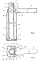
- the device for producing biscuits shown in the drawings has a cylindrical housing 1, which is closed on its lower end by a screwed-on or bounced mouthpiece 2 and which is drawn inwards at the upper end 3.
- a piston 4 (see FIG. 2) is guided in the housing 1 and can be driven via a piston rod 5 by means of a push lever 6.
- the upper end 7 of the piston rod 5 passes through the upper end 3 of the housing 1 through an opening 8. It can have a recessed grip 9 on its upper end 7 on opposite sides for rotation about its own axis.
- a pawl 11 cooperates with the one toothed strip 10, which is integrally formed on the push lever 6 and is designed in the manner of a spring nose 12.
- the push lever 6 has in its area near the container a fork head with two fork legs 13, 14, the spring lug 12 being arranged between the two fork legs 13, 14 approximately in the longitudinal axis of the push lever 6.
- At the free ends of the fork legs 13, 14 outwardly facing journals 15, 16 are formed, which engage in bearing openings 17, 18 in the upper end 3 of the housing.
- the upper end 3 of the housing has on its side facing the push lever 6 a wide opening 19 through which the push lever can be inserted, the trunnions 15, 16 sliding with their outer end face along the substantially straight wall 20 of the housing 1 there until the trunnions 15, 16 finally snap into the bearing openings 17, 18.
- the bearing pins 15, 16 are held in their position.
- a backstop 21 is arranged above the push lever 6, which also engages in the toothed rack 10 and, when the push lever 6 is lifted from the end position shown in FIG prevented.
- the backstop 21 is also designed to be resilient so that it can slide over the toothed strip 10 when the piston rod 5 moves downward.
- the substantially circular opening 8 in the upper end 3 of the housing 1 is on one side extended to slots 22 leading to both sides, so that the backstop 21 is formed by a narrow, web-shaped wall 23 of the housing and thereby receives its spring property.
- the piston rod 5 has a further toothed strip 24 on the side opposite the toothed strip 10, which however has a different tooth pitch and consequently each individual tooth leads to a different stroke than the teeth on the toothed strip 10. Furthermore, the piston rod is offset from the toothed strips 10, 24 with flats 25 which, after the piston rod 7 has been rotated about its own axis, allow the piston rod to be returned from the end position shown in FIG. 2 to the starting position in which the piston 4 is below the Upper end 3 of the housing 1 is located and the housing 1 can be filled with dough.
- a number of axially parallel ribs 26 corresponding to the number of toothed racks 10, 24 are formed on the piston rod, which engage in corresponding axially parallel guide grooves 27 and which hold the toothed ratchet 11 respectively positioned in relation to the pawl 11, thus securing the piston rod against rotation.
- FIGS. 4 and 5 differs from that according to FIGS. 2 and 3 essentially only in that the piston rod has the same toothed rack 10 on opposite sides and the pawls 11 on the mutually facing inner sides of the fork legs 13, 14 in shape below facing strips 28 are arranged.
- the fork legs 13, 14 on the bearing pins 15, 16 have a somewhat greater axial play in order to allow the strips 28 to rebound.
- each toothed strip 10 is assigned a backstop 21 which is formed on opposite sides of the opening 8.
- FIGS. 6 and 7 show a modified version of the mouthpiece 2 for producing decorative pastries.
- the cylindrical mouthpiece has a certain height and, in the exemplary embodiment shown, has four upwardly open chambers 30 to 33, of which the central cylindrical chamber 30 has the outlet openings 34 for the dough, while the chambers 31, 32, 33 surrounding the chamber 30 follow closed at the bottom and connected to the central chamber 30 via transverse openings 35 in the respective partition.
- the chambers 31, 32, 33 another, for. B. filled with different colored dough than in the housing 1, so that each time a metered amount of dough from the adjacent chambers 31, 32 and 33 is fed to the dough strand when pressing out the main dough mass through the chamber.
- the mouthpiece 2 finally has at least three feet 36, by means of which the device on a base, for. B. a baking sheet, can be set up and create the necessary distance for the dough to emerge from the surface.
- the housing 1 is designed somewhat differently on its upper end face.
- the piston rod 5 also passes through an opening 8 in the housing.
- the push lever 6 engages with its pawl 11 in a toothed strip 10 of the piston rod 5.
- the push lever 6 is pivotally mounted with the bearing pins 15, 16 in the bearing openings 17, 18 of the housing 1.
- precautions are taken on the fork legs 13, 14 and / or on the inside of the housing in the movement path of the fork legs, e.g. B. contact surfaces od.
- Like. Arranged which release the trunnions 15, 16 from the bearing openings 17, 18 when pulling the push lever into the highest position. This can be done, for example, by resilient yielding of the opposite one Housing walls or - after turning the piston rod - by compressing the fork legs 13, 14 so that the push lever 6 can be removed from the housing 1 (dash-dotted position in Figure 8 and Figure 9).
- FIG. 10 shows a garnishing nozzle 37 which, in the exemplary embodiment shown, consists of a mouthpiece 38 with an outlet opening 39 and an attached nozzle 40 with the actual nozzle opening 41.
- the Garnierdüse can either be placed directly on the front of the housing or on one of the mouthpieces described above.
Landscapes
- Life Sciences & Earth Sciences (AREA)
- Engineering & Computer Science (AREA)
- Food Science & Technology (AREA)
- Manufacturing And Processing Devices For Dough (AREA)
- Confectionery (AREA)
Applications Claiming Priority (2)
| Application Number | Priority Date | Filing Date | Title |
|---|---|---|---|
| DE19873733325 DE3733325A1 (de) | 1987-10-02 | 1987-10-02 | Vorrichtung zur portionsweisen abgabe pastoeser massen, z. b. gebaeckteig |
| DE3733325 | 1987-10-02 |
Publications (2)
| Publication Number | Publication Date |
|---|---|
| EP0309977A2 true EP0309977A2 (fr) | 1989-04-05 |
| EP0309977A3 EP0309977A3 (fr) | 1990-03-21 |
Family
ID=6337469
Family Applications (1)
| Application Number | Title | Priority Date | Filing Date |
|---|---|---|---|
| EP88115854A Withdrawn EP0309977A3 (fr) | 1987-10-02 | 1988-09-27 | Appareil pour la distribution de porions d'une matière pâteuse, par exemple, pâte de patisserie |
Country Status (2)
| Country | Link |
|---|---|
| EP (1) | EP0309977A3 (fr) |
| DE (1) | DE3733325A1 (fr) |
Cited By (1)
| Publication number | Priority date | Publication date | Assignee | Title |
|---|---|---|---|---|
| GR1001105B (el) * | 1991-06-24 | 1993-04-28 | Nikolaos Moutafis | Μορφοποιητης ζυμης. |
Family Cites Families (12)
| Publication number | Priority date | Publication date | Assignee | Title |
|---|---|---|---|---|
| CH184284A (de) * | 1935-09-26 | 1936-05-31 | Fred P Hoffmann | Gerär zur Herstellung von Formstücken aus Teig und andern plastischen Massen. |
| DE958011C (de) * | 1951-01-12 | 1957-02-14 | Sawa Fabriks Aktiebolag | Vorrichtung zum Herstellen von Formstuecken aus Teig oder anderen plastischen Massen |
| GB696310A (en) * | 1951-03-28 | 1953-08-26 | Nathan Stone | Improvements in or relating to dispensing containers |
| FR1075003A (fr) * | 1952-03-19 | 1954-10-12 | Gerdes & Co | Récipient comportant un dispositif permettant de prélever des quantités partielles de son contenu, en particulier distributeur de moutarde |
| FR1200293A (fr) * | 1958-03-27 | 1959-12-21 | Distributeur doseur | |
| US3002658A (en) * | 1959-07-06 | 1961-10-03 | Sigmund T Sajda | Nozzle for applying colors |
| DE1763688A1 (de) * | 1968-07-18 | 1972-02-24 | Anker Werke Ag | Verfahren und Anordnung zur Herabsetzung der Ausschwingungsdauer eines Schrittmotors |
| US4122976A (en) * | 1976-11-11 | 1978-10-31 | Colgate-Palmolive Company | Dispensing |
| DE2704432C3 (de) * | 1977-02-03 | 1979-11-08 | Gerdes Gmbh & Co, 5830 Schwelm | Handpresse zur portionsweisen Abgabe von Teig u.a. pastösen Nahrungsmitteln |
| DE3215362C1 (de) * | 1982-04-24 | 1983-08-11 | Gerdes Gmbh & Co, 5830 Schwelm | Handpresse zur portionsweisen Abgabe von Teig und aehnlichem pastoesem Gut wie z.B. Creme od.dgl. |
| DE8214557U1 (de) * | 1982-05-14 | 1982-11-04 | So, Shun, Kowloon | Vorrichtung zum extrudieren von ess- und speisewaren |
| DE8229452U1 (de) * | 1982-10-21 | 1983-05-05 | Haushaltsprodukte Vertriebsgesellschaft mbH, 5430 Montabaur | Vorrichtung zum herstellen von formstuecken aus teig |
-
1987
- 1987-10-02 DE DE19873733325 patent/DE3733325A1/de active Granted
-
1988
- 1988-09-27 EP EP88115854A patent/EP0309977A3/fr not_active Withdrawn
Cited By (1)
| Publication number | Priority date | Publication date | Assignee | Title |
|---|---|---|---|---|
| GR1001105B (el) * | 1991-06-24 | 1993-04-28 | Nikolaos Moutafis | Μορφοποιητης ζυμης. |
Also Published As
| Publication number | Publication date |
|---|---|
| EP0309977A3 (fr) | 1990-03-21 |
| DE3733325C2 (fr) | 1989-11-02 |
| DE3733325A1 (de) | 1989-04-13 |
Similar Documents
| Publication | Publication Date | Title |
|---|---|---|
| DE3227112C2 (fr) | ||
| EP0532728B1 (fr) | Dispositif de remplissage de gaines de cigarettes | |
| EP0615787B1 (fr) | Distributeur manuel pour cartouche double | |
| EP1173078B1 (fr) | Distributeur de creme et de deodorant | |
| DE2519108A1 (de) | Abgabekappe fuer aerosoldruckdosen | |
| EP3058516B1 (fr) | Compteur et appareil portatif équipé d'un compteur | |
| DE19854296A1 (de) | Extruder für teigartige Lebensmittelsubstanzen | |
| EP0276474A2 (fr) | Appareil de dosage | |
| DE10020591B4 (de) | Ausgabevorrichtung für viskoses Dentalmaterial | |
| DE2528191C3 (de) | Spender zur Einzelabgabe von als Schüttgut vordosierten Partikeln einheitlicher Form und Grosse | |
| DE2925432C2 (fr) | ||
| WO2019007987A1 (fr) | Poste de préparation pour restaurant rapide | |
| DE69907039T2 (de) | Biegsamer antriebsmechanismus sowie abgabevorrichtung enthaltend einen solchen mechanismus | |
| EP0315077A1 (fr) | Distributeur pour produits pâteux | |
| EP0248278A2 (fr) | Distributeur pour délivrer les doses unitaires d'une pâte ou similaire | |
| DE3733325C2 (fr) | ||
| DE60112417T2 (de) | Schminkset und aufbewahrungsetui für kosmetika | |
| EP0431304A2 (fr) | Dispositif pour l'expulsion par étapes d'un produit | |
| EP0267207A1 (fr) | Dispositif pour l'application de matieres liquides ou pateuses | |
| DE2704432C3 (de) | Handpresse zur portionsweisen Abgabe von Teig u.a. pastösen Nahrungsmitteln | |
| DE4001082C1 (en) | Simple dispenser for discharging metered amts. of dough - can change portion size by altering cap between discharge aperture and tapered lower end of a plug at foot of axial shaft | |
| DE8229452U1 (de) | Vorrichtung zum herstellen von formstuecken aus teig | |
| CH629994A5 (en) | Apparatus for comminuting fruit, onions, other vegetables or the like | |
| DE19746101A1 (de) | Seifenspender | |
| DE1475178C (de) | Einteiliger Sprühkopf aus Kunststoff für einen Aerosolbehälter |
Legal Events
| Date | Code | Title | Description |
|---|---|---|---|
| PUAI | Public reference made under article 153(3) epc to a published international application that has entered the european phase |
Free format text: ORIGINAL CODE: 0009012 |
|
| AK | Designated contracting states |
Kind code of ref document: A2 Designated state(s): AT BE CH DE ES FR GB IT LI NL SE |
|
| PUAL | Search report despatched |
Free format text: ORIGINAL CODE: 0009013 |
|
| AK | Designated contracting states |
Kind code of ref document: A3 Designated state(s): AT BE CH DE ES FR GB IT LI NL SE |
|
| STAA | Information on the status of an ep patent application or granted ep patent |
Free format text: STATUS: THE APPLICATION IS DEEMED TO BE WITHDRAWN |
|
| 18D | Application deemed to be withdrawn |
Effective date: 19900922 |