EP0309990B1 - Hologon und Verfahren zu seiner Herstellung - Google Patents
Hologon und Verfahren zu seiner Herstellung Download PDFInfo
- Publication number
- EP0309990B1 EP0309990B1 EP88115884A EP88115884A EP0309990B1 EP 0309990 B1 EP0309990 B1 EP 0309990B1 EP 88115884 A EP88115884 A EP 88115884A EP 88115884 A EP88115884 A EP 88115884A EP 0309990 B1 EP0309990 B1 EP 0309990B1
- Authority
- EP
- European Patent Office
- Prior art keywords
- diffraction
- axis
- region
- mask
- precursor
- Prior art date
- Legal status (The legal status is an assumption and is not a legal conclusion. Google has not performed a legal analysis and makes no representation as to the accuracy of the status listed.)
- Expired - Lifetime
Links
- 238000004519 manufacturing process Methods 0.000 title claims description 9
- 230000000694 effects Effects 0.000 claims description 23
- 239000002243 precursor Substances 0.000 claims description 22
- 239000011248 coating agent Substances 0.000 claims description 20
- 238000000576 coating method Methods 0.000 claims description 20
- 238000000034 method Methods 0.000 claims description 6
- 230000005855 radiation Effects 0.000 claims description 4
- 239000000758 substrate Substances 0.000 claims 7
- 230000000873 masking effect Effects 0.000 claims 2
- 239000000463 material Substances 0.000 claims 2
- 229920002120 photoresistant polymer Polymers 0.000 description 14
- 238000010586 diagram Methods 0.000 description 4
- 238000006073 displacement reaction Methods 0.000 description 3
- 230000001427 coherent effect Effects 0.000 description 2
- 239000011521 glass Substances 0.000 description 2
- 230000003247 decreasing effect Effects 0.000 description 1
- 230000002452 interceptive effect Effects 0.000 description 1
Images




Classifications
-
- G—PHYSICS
- G02—OPTICS
- G02B—OPTICAL ELEMENTS, SYSTEMS OR APPARATUS
- G02B26/00—Optical devices or arrangements for the control of light using movable or deformable optical elements
- G02B26/08—Optical devices or arrangements for the control of light using movable or deformable optical elements for controlling the direction of light
- G02B26/10—Scanning systems
- G02B26/106—Scanning systems having diffraction gratings as scanning elements, e.g. holographic scanners
-
- Y—GENERAL TAGGING OF NEW TECHNOLOGICAL DEVELOPMENTS; GENERAL TAGGING OF CROSS-SECTIONAL TECHNOLOGIES SPANNING OVER SEVERAL SECTIONS OF THE IPC; TECHNICAL SUBJECTS COVERED BY FORMER USPC CROSS-REFERENCE ART COLLECTIONS [XRACs] AND DIGESTS
- Y10—TECHNICAL SUBJECTS COVERED BY FORMER USPC
- Y10S—TECHNICAL SUBJECTS COVERED BY FORMER USPC CROSS-REFERENCE ART COLLECTIONS [XRACs] AND DIGESTS
- Y10S359/00—Optical: systems and elements
- Y10S359/90—Methods
Definitions
- This invention relates to hologons and their methods of manufacture.
- a hologon is a device which, when rotated, causes a stationary beam directed at it to repetitively scan along a line.
- Hologons which comprise a disc mounted for rotation at high speed.
- the disc has, on a planar surface to which the axis of rotation is perpendicular, a plurality of sector-shaped facets.
- Each facet contains a diffraction grating. If there are 'n' facets, the inclination of grating lines in one facet to the lines in adjacent facets is The lines may be 'tangential' or 'radial'. If 'radial', the lines of a facet are parallel to a radius which bisects the facet.
- the lines are perpendicular to the radius which bisects the facet.
- the gratings may be reflective or transmissive.
- Hologons are also known which contain a single grating pattern. Such single facet hologons cause two scans per revolution. Multifaceted hologons having 'n' facets cause 'n' scans per revolution. Hologons are also known in which each facet has power.
- a radiation beam usually a laser beam
- the exposure creates in the photosensitive coating a precursor of a grating pattern.
- the extent of the precursor created is limited by a mask which has an aperture bounded in part by two, radially inner and radially outer boundaries and opposed lateral boundaries radial to the axis of rotation of the disc.
- the angle included between the lines is the same as the included angle of the facet, i.e.
- the disc After one facet has been exposed, the disc is rotated through an angle of relative to the mask and the means for directing the radiation beams at the disc, and another facet is exposed. After all 'n' facets have been exposed, the coating is processed to produce operative gratings from the precursors in the photosensitive coating.
- Duty cycle has been understood to mean the percentage of time during which the scanner is useful.
- the scanner is, for example, not useful when the incident beam is incident on two facets. Some have regarded the duty cycle as being the percentage of time in which the beam is incident exclusively on only one facet. However, the scanner is also not useful when the beam is incident, partially or wholly, on the diffraction effects resulting from the diffraction caused by the opposed lateral boundaries of the mask.
- each junction between two facets there are two sets of diffraction effects, one for each facet and they extend from the junction clockwise or counterclockwise, respectively, into the facet.
- the diffraction effects are of substantially constant width so that their effect on duty cycle varies with radial distance from the axis of rotation; it being greater the closer to the axis.
- a known hologon 20 which comprises a glass disc 22 with a coating 24 of photoresist.
- the disc 22 has an aperture 26 coaxial with the geometric axis 28 of the disc 22, for receiving a drive shaft (not shown) to which the hologon is secured for rotation in unison with the shaft.
- the hologon 20, illustrated in Fig. 1, has six facets F1-F6 each subtending an angle of 60° at the axis 28. There are radial boundaries B12, B23, B34, B45, B56 and B61 between the facets F1 and F2, F2 and F3, and so on, respectively. Each facet has a radially inner boundary 23 and a radially outer boundary 25 both of which are arcs of respective circles.
- the facets may be termed generally sector-shaped even though they are sectors truncated by the boundaries 23.
- the photoresist coating 24 in each facet has been exposed and processed to exhibit a diffraction grating pattern.
- the diffraction grating is a plurality of straight, closely spaced lines 30 (only a very few of which are shown in the drawing) which, when light is incident on the grating, cause diffraction of the light.
- the lines 30 in each facet F1-F6 are parallel to a line R1-R6, respectively, which is a radius bisecting the respective facet.
- the lines in each facet are termed tangential and are perpendicular to the line R1-R6 in each respective facet.
- the diffraction grating lines 30 in each facet F1-F6 are formed by interfering two coherent beams so that an interference pattern is created on the photoresist.
- the interference pattern creates in the photoresist a precursor of a grating pattern.
- a mask limits the extent of the interference pattern. After one exposure there is relative displacement so that another facet can be exposed. After all facets have been exposed, the photoresist is processed and the grating patterns result.
- Fig. 3 illustrates schematically an apparatus 32 for creating the grating pattern precursors in the photoresist coating 24.
- the apparatus includes a rotary table 34 mounted from a base 38, for rotation about an axis 36.
- Drive means 40 are provided for driving the table 34 in rotation and for holding it in desired positions.
- a prism assembly 42 is mounted from the base 38 by support structure 44.
- the prism assembly 42 has a beam splitting interface 46 between two prisms 48 and 50.
- the plane of the interface 46 contains the axis 36.
- a mask 52 is disposed between the prism assembly 42 and the disc 22 and is supported by the support structure 44.
- a laser 54 provides a source of coherent, substantially monochromatic light which is directed as collimated beam 56 at a face 58 of the prism assembly 42.
- the mask 52 is illustrated in Fig. 4 and consists of an opaque plate 60 having an aperture 62.
- the aperture has a radially inner, smaller diameter circular arcuate boundary 64 and a larger diameter, radially outer circular arcuate boundary 66.
- the circular arcuate forms of the boundaries 64 and 66 have a common center 68.
- the other two boundaries 70 and 72 of the aperture 62 termed herein opposed lateral boundaries, are rectilinear and, as shown, are radial to the circular arcuate forms of the boundaries 64 and 66.
- the mask 52, supported by the support structure 44, is disposed with the center 68 on the axis 36.
- a glass disc 22 with photoresist coating 24 thereon is positioned on the table 34.
- the laser 54 is energized and its output beam 56 enters the prism assembly 42 through face 58.
- the beam is incident on the interface 46 which splits the beam into beam 74 and beam 76.
- Beam 74 is reflected off face 78 and leaves the prism assembly 42, as beam 80, through face 82.
- Beam 76 is reflected off face 84 and leaves the prism assembly 42, as beam 86, through face 88.
- the prism assembly 42 is so located and the beam 56 is of such cross-sectional size and shape that the beams 80 and 86 fill the aperture 62.
- the beams 80 and 86 interfere and form an interference pattern on the photoresist coating 24.
- the interference pattern is a plurality of bright and dark parallel lines which are parallel to the radius R1 from the axis 36, which radius bisects the angle included between opposed lateral boundaries 70 and 72 of the aperture 62 in the mask 52.
- the hologon to be produced has six facets, therefore the drive means 40 rotates the table through exactly 60° i.e., and holds the table 34 in its new position.
- the exposure process is repeated and the table is again stepped. This procedure is repeated four more times so that precursors of the six facets F1-F6 are created in the photoresist coating 24 by the six interference patterns to which the coating is exposed.
- edges 70 and 72 of the aperture 62 have been radial to the center 68 and, in an example which has six facets, have included an angle of 60° and the center 68 has been on the axis 36.
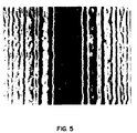
- Fig. 5 illustrates a portion of the interference patterns at each side of a boundary, for example, B12, between two facets F1 and F2 after processing of the precursors. It will be recognized: that the lines illustrated in Fig. 5 are those created by diffraction at the boundaries 70 and 72; that they are not the lines created by interference of the beams 80 and 86 which lines are too fine to show in the photograph from which Fig. 5 is reproduced; and that they are parallel to the boundaries 70 and 72 (and to the boundary B12) and not parallel to the bisector R of the facet.
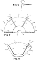
- Fig. 6 represents the intensity of light in the interference pattern which is represented to the right of boundary B12 in Fig. 5.
- the location of boundary B12 is drawn in Fig. 6 to aid understanding.
- the interference pattern termed herein diffraction effects, created by diffraction at the boundaries 70 and 72 of the mask aperture 62 creates a precursor in the photoresist which creates a line pattern when the photoresist coating is processed.
- the line pattern resulting from the diffraction reduces the angular extent of the facet which is usable and hence the duty cycle of the hologon is reduced. Such reduction is undesirable and it is a purpose of the present invention to reduce the reduction and to more nearly approach the theoretical duty cycle.
- Fig. 7 represents the regions 75 of diffraction effects in three facets F1, F2 and F6, with manufacture in accordance with the prior art.
- Each region 75 is shown as having a width D in which the hologon is not usable.
- width D in which the hologon is not usable.
- width 2D which is not usable. It will be recognized that the region 75 clockwise from boundary B12 is created when facet F2 is being exposed and the pattern counterclockwise from boundary B12 is created when the facet F1 is being exposed.
- the precursors created by the diffraction at the lateral boundaries of adjacent facets are overlapped one over the other rather than created in adjacent contiguous but non-overlapping regions of the photosensitive layer. This is achieved by making the aperture in the mask subtend an angle greater than wherein n is the number of facets.
- the overlap may be such that one diffraction effect lies entirely on top of another or it may be such that there is just some, rather than total, overlap. The greatest advantage is achieved when there is total overlap.
- the present invention also resides in a hologon as defined in Claim 5.
- the above-described diffraction produced interference patterns are overlapped, for example, as illustrated in Fig. 8 so that the width dimension of the unusable region may be as little as D.
- Fig. 8 shows the pattern fully overlapped but in other embodiments the patterns are partially overlapped. Such other embodiments also give improvements in the duty cycle although not the maximum achievable improvement.
- the overlapping of the diffraction patterns is achieved by giving the aperture 62 in the mask 52 an extent, considered in an arcuate sense about the center 68, greater than wherein n is the number of facets.
- the aperture may be given such greater extent by increasing the angle included between boundaries 70 and 72 to an angle greater than or the included angle can be with the intersection point of the boundaries 70 and 72 spaced from and behind the axis 36.
- Fig. 9 represents the former embodiment and Fig. 10 represents the latter embodiment.
- the embodiment represented in Fig. 9 leads to an overlap of the diffraction patterns which varies in width, i.e, the dimension considered in the arcuate or tangential sense, with radius.
- the embodiment represented in Fig. 10 gives an overlap which is of uniform width independent of radius. While the former might initially seem to be less preferable than the latter, it should be borne in mind that the use of a hologon is probably known during its manufacture and hence the radius at which the small cross-section beam is incident, in use, on the hologon is also known.
- the angle included between the two boundaries 70 and 72 can be so selected that the overlap of the two regions of diffraction effects has the desired extent, in the arcuate, or tangential, sense, at the radius at which the light beam will be incident on the hologon in use.
- the overlap will be excessive and radially inwardly from the selected radius, the overlap will be less than that which provides the maximum duty cycle.
- Fig. 10 illustrates an alternative arrangement in which the angle included by the lateral boundaries of the mask is but the point of intersection of the lines of the lateral boundaries is displaced behind the axis 28.
- the facets are designated F1 ⁇ -F6 ⁇ but the projections of the lateral boundaries of the mask onto the photosensitive coating 24 are designated 70A and 72A, respectively.
- the point of intersection of the lines of the lateral boundaries of the mask is designated X.
- Such lateral boundaries may be regarded as approximately radial.
- the point of intersection of the lines of the mask edges when: facet F1 ⁇ is being exposed, is designated X1; facet F2 ⁇ is being exposed, is designated X2; etc.
- Fig. 12 represents the relationship between h and the dimension D which again is the width of the area of diffraction effects created during each exposure and which is unusable. In Fig. 10, the unusable areas are shown overlapped with a width dimension D. It will be understood that
Landscapes
- Physics & Mathematics (AREA)
- General Physics & Mathematics (AREA)
- Optics & Photonics (AREA)
- Diffracting Gratings Or Hologram Optical Elements (AREA)
- Mechanical Optical Scanning Systems (AREA)
- Holo Graphy (AREA)
Claims (5)
- Verfahren zum Herstellen eines Hologons mit einer Vielzahl von n Facetten (F), von denen jede in einer Beschichtung ein Beugungsgittermuster bildet, wobei
ein Substrat (22) vorgesehen ist, um dessen Achse (28) das Hologon bei Gebrauch drehbar ist,
eine lichtempfindliche Schicht (24) auf das Substrat aufgebracht wird,
Strahlenbündel von einem Strahlung erzeugenden Mittel (54) auf die lichtempfindliche Schicht (24) gerichtet werden, um auf der Schicht ein erstes Interferenzmuster zu erzeugen, das in der Schicht die Ausgangsbasis für ein Beugungsgitter bildet,
die Strahlenbündel mittels einer Maske (52) eingegrenzt werden, wodurch das Interferenzmuster in einem ersten Bereich der Schicht entsteht,
das Substrat, die Strahlenbündel und die Maske um einen Winkelbetrag von
die lichtempfindliche Schicht entwickelt wird, wobei ausgehend von der durch die Interferenzmuster gebildeten Ausgangsbasis Beugungsgitter in der lichtempfindlichen Schicht erzeugt werden,
dadurch gekennzeichnet, daß
der Arkus jedes Bereichs der lichtempfindlichen Schicht etwas größer ist als
- Verfahren nach Anspruch 1, dadurch gekennzeichnet, daß
jeder Bereich radial zur Achse verlaufende Seiten aufweist und daß die sich überlappenden Beugungseffekte in einem sich in Richtung der Achse (28) verjüngenden Bereich vorhanden sind. - Verfahren nach Anspruch 1, dadurch gekennzeichnet, daß
jeder Bereich Seiten aufweist, deren Linien sich in einem von der Achse (28) beabstandeten und jenseits der Achse befindlichen Punkt schneiden, und daß die sich überlappenden Beugungseffekte in Bereichen mit im wesentlichen parallel zueinander verlaufenden seitlichen Begrenzungen auftreten. - Verfahren nach Anspruch 1, dadurch gekennzeichnet, daß
das Hologon im allgemeinen sektorförmige, gleichmäßig um dessen Achse verteilte Facetten besitzt und zum Empfangen eines in einem Radialabstand r von der Achse auftreffenden Strahlenbündels dient, das bei erfolgender Drehung des Hologons um die Achse (28) von einem ruhenden Strahlenbündel zu einem Abtaststrahlenbündel umgewandelt wird,
eine Maske (52) vorgesehen ist, deren Ausschnitt (62) erste und zweite Begrenzungskanten (70, 72) aufweist, die sich radial oder nahezu radial zur Achse (28) erstrecken, wodurch in der lichtempfindlichen Schicht eine erste Ausgangsbasis für ein Beugungsgittermuster entsteht,
das Substrat, die Strahlenbündel und die Maske verdreht werden, um ein weiteres Interferenzmuster zu erzeugen, das die Ausgangsbasis für ein weiteres Beugungsgittermuster bildet, dessen Linien in einem Winkel von
die fotografische Schicht verarbeitet wird, um Beugungsgitter zu erzeugen, wobei
der von dem sich auf dem Radius r zwischen der ersten und zweiten Begrenzungskante (70, 72) des Ausschnitts (62) der Maske erstreckenden Bogen an der Achse eingeschlossene Winkel um einen Winkel α größer ist als

- Hologon mit einer Vielzahl von Facetten (F₁′-F₆′; F₁˝-F₆˝) wobei
ein Substrat (22) mit einer Achse (28) vorgesehen ist, um die das Substrat bei Gebrauch drehbar ist,
jede Facette (F₁′-F₆′; F₁˝-F₆˝) radial innere, radial äußere und einander gegenüberliegende seitliche Begrenzungen (23, 25) umfaßt,
das Substrat (22) eine Beschichtung aufweist, die durch Verarbeiten eines lichtempfindlichen Materials gebildet ist,
jede Facette (F₁′-F₆′; F₁˝-F₆˝) in der Beschichtung ein Beugungsgittermuster aufweist, dessen Ausgangsbasis im lichtempfindlichen Material optisch durch eine Maske (52) umfassende Mittel gebildet worden ist und das jeweils Linien (30) aufweist, die sich von der die Facette (F₁′-F₆′; F₁˝- F₆˝) schneidenden Achse (28) aus parallel oder senkrecht zu einem Radius (R₁-R₆) erstrecken, wobei jede Facette (F₁′-F₆′; F₁˝-F₆˝) zwei Bereiche (75) von Beugungseffekten umfaßt, von denen jeweils ein Bereich mit jeder der einander gegenüberliegenden seitlichen Begrenzungen der Facette (F₁′-F₆′; F₁˝-F₆˝) in Berührung steht, wobei die Beugungseffekte durch Beugung an Kanten (70, 72; 70A, 72A) der Maske (52) entstehen und wobei jeder der Bereiche (75) der Beugungseffekte Linien aufweist, die sich parallel zu den einander gegenüberliegenden seitlichen Begrenzungen erstrecken, mit denen der betreffende Bereich der Beugungseffekte in Berührung steht,
dadurch gekennzeichnet, daß
jede Facette (F₁′-F₆′; F₁˝-F₆˝) die ihr benachbart angeordnete Facette überlappt und jeder Bereich (75) von Beugungseffekten einen Bereich von Beugungseffekten einer benachbarten Facette (F₁′-F₆′; F₁˝-F₆˝) überlappt.
Applications Claiming Priority (2)
| Application Number | Priority Date | Filing Date | Title |
|---|---|---|---|
| US101539 | 1987-09-28 | ||
| US07/101,539 US4787688A (en) | 1987-09-28 | 1987-09-28 | Hologon and method of manufacturing a hologon |
Publications (3)
| Publication Number | Publication Date |
|---|---|
| EP0309990A2 EP0309990A2 (de) | 1989-04-05 |
| EP0309990A3 EP0309990A3 (en) | 1990-08-22 |
| EP0309990B1 true EP0309990B1 (de) | 1994-08-24 |
Family
ID=22285172
Family Applications (1)
| Application Number | Title | Priority Date | Filing Date |
|---|---|---|---|
| EP88115884A Expired - Lifetime EP0309990B1 (de) | 1987-09-28 | 1988-09-27 | Hologon und Verfahren zu seiner Herstellung |
Country Status (5)
| Country | Link |
|---|---|
| US (1) | US4787688A (de) |
| EP (1) | EP0309990B1 (de) |
| JP (1) | JPH01302220A (de) |
| CA (1) | CA1308282C (de) |
| DE (1) | DE3851192T2 (de) |
Families Citing this family (9)
| Publication number | Priority date | Publication date | Assignee | Title |
|---|---|---|---|---|
| US4840443A (en) * | 1988-05-31 | 1989-06-20 | Eastman Kodak Company | Holographic scanner spinner |
| US4988154A (en) * | 1988-09-16 | 1991-01-29 | Wisconsin Alumni Research Foundation | Method and apparatus of producing an arcuate rainbow hologram |
| US5253088A (en) * | 1992-04-27 | 1993-10-12 | Eastman Kodak Company | Method to reduce cross scan error visibility during manufacture of a hologon |
| US5255108A (en) * | 1992-04-27 | 1993-10-19 | Eastman Kodak Company | Method of maximizing the frequency of adjacent facet cross scan error such that the increased spatial frequency reduces the visual perception of the exposure error |
| EP0568469A1 (de) * | 1992-04-27 | 1993-11-03 | Eastman Kodak Company | Verfahren zur Herstellung eines Hologons mit reduzierter Sichtbarkeit des Querabtastfehlers |
| KR20020033761A (ko) * | 1999-08-11 | 2002-05-07 | 추후제출 | 이동 가능한 회절성 광 소자에 의해 광 신호를 처리하는방법 및 시스템 |
| WO2001065469A1 (en) * | 2000-03-02 | 2001-09-07 | Physical Optics Corporation | Scanner utilizing light pipe with diffuser |
| US10101652B2 (en) * | 2015-09-24 | 2018-10-16 | Ushio Denki Kabushiki Kaisha | Exposure method, method of fabricating periodic microstructure, method of fabricating grid polarizing element and exposure apparatus |
| JP2022508697A (ja) * | 2018-10-12 | 2022-01-19 | ブリスライツ,エルエルシー | レーザ投影装置および3d画像作成方法 |
Family Cites Families (3)
| Publication number | Priority date | Publication date | Assignee | Title |
|---|---|---|---|---|
| US4289371A (en) * | 1979-05-31 | 1981-09-15 | Xerox Corporation | Optical scanner using plane linear diffraction gratings on a rotating spinner |
| US4455061A (en) * | 1980-07-31 | 1984-06-19 | The Regents Of The University Of Minnesota | Multi-faceted holographic optical element and methods of making and using same |
| JPS599625A (ja) * | 1982-07-08 | 1984-01-19 | Ricoh Co Ltd | ホログラムスキヤナ− |
-
1987
- 1987-09-28 US US07/101,539 patent/US4787688A/en not_active Expired - Lifetime
-
1988
- 1988-08-02 CA CA000573602A patent/CA1308282C/en not_active Expired - Fee Related
- 1988-09-27 EP EP88115884A patent/EP0309990B1/de not_active Expired - Lifetime
- 1988-09-27 DE DE3851192T patent/DE3851192T2/de not_active Expired - Fee Related
- 1988-09-27 JP JP63242189A patent/JPH01302220A/ja active Pending
Also Published As
| Publication number | Publication date |
|---|---|
| EP0309990A3 (en) | 1990-08-22 |
| EP0309990A2 (de) | 1989-04-05 |
| DE3851192D1 (de) | 1994-09-29 |
| JPH01302220A (ja) | 1989-12-06 |
| US4787688A (en) | 1988-11-29 |
| DE3851192T2 (de) | 1995-04-06 |
| CA1308282C (en) | 1992-10-06 |
Similar Documents
| Publication | Publication Date | Title |
|---|---|---|
| US4609259A (en) | Process for producing micro Fresnel lens | |
| CN100385285C (zh) | 多光束多面镜扫描系统 | |
| EP0299964B1 (de) | Abtastvorrichtung | |
| EP0477348A1 (de) | Holographisches abtastgerät mit bündelanpassendem optischen beugungsgitter | |
| EP0547205A1 (de) | Einstrahl vielfarben holographisches abtastgerät. | |
| US4787688A (en) | Hologon and method of manufacturing a hologon | |
| JPH06109994A (ja) | 画像形成装置 | |
| JPH10227992A (ja) | ベッセルビーム発生方法及びそれを用いた光走査装置 | |
| US3795446A (en) | Lithography | |
| US4840443A (en) | Holographic scanner spinner | |
| US5255108A (en) | Method of maximizing the frequency of adjacent facet cross scan error such that the increased spatial frequency reduces the visual perception of the exposure error | |
| JP2841441B2 (ja) | 回折格子およびその製作方法 | |
| US5253088A (en) | Method to reduce cross scan error visibility during manufacture of a hologon | |
| JPH07151910A (ja) | 回折格子露光方法 | |
| JPH06264272A (ja) | 微細加工法 | |
| JPH10323787A (ja) | レーザ加工装置 | |
| JPS58184901A (ja) | 回転鏡 | |
| US6181447B1 (en) | Laser scanning unit | |
| EP0069306A2 (de) | Hologrammabtaster | |
| JPS6321128B2 (de) | ||
| RU1099747C (ru) | Устройство для записи радиальной дифракционной решетки | |
| JPS6118729B2 (de) | ||
| EP0568469A1 (de) | Verfahren zur Herstellung eines Hologons mit reduzierter Sichtbarkeit des Querabtastfehlers | |
| JPH0320711A (ja) | ホログラムディスク | |
| SU1303977A1 (ru) | Установка дл маркировки изделий |
Legal Events
| Date | Code | Title | Description |
|---|---|---|---|
| PUAI | Public reference made under article 153(3) epc to a published international application that has entered the european phase |
Free format text: ORIGINAL CODE: 0009012 |
|
| AK | Designated contracting states |
Kind code of ref document: A2 Designated state(s): AT BE CH DE ES FR GB GR IT LI LU NL SE |
|
| PUAL | Search report despatched |
Free format text: ORIGINAL CODE: 0009013 |
|
| AK | Designated contracting states |
Kind code of ref document: A3 Designated state(s): AT BE CH DE ES FR GB GR IT LI LU NL SE |
|
| 17P | Request for examination filed |
Effective date: 19901217 |
|
| 17Q | First examination report despatched |
Effective date: 19930202 |
|
| RBV | Designated contracting states (corrected) |
Designated state(s): DE FR GB |
|
| GRAA | (expected) grant |
Free format text: ORIGINAL CODE: 0009210 |
|
| AK | Designated contracting states |
Kind code of ref document: B1 Designated state(s): DE FR GB |
|
| REF | Corresponds to: |
Ref document number: 3851192 Country of ref document: DE Date of ref document: 19940929 |
|
| ET | Fr: translation filed | ||
| PLBE | No opposition filed within time limit |
Free format text: ORIGINAL CODE: 0009261 |
|
| STAA | Information on the status of an ep patent application or granted ep patent |
Free format text: STATUS: NO OPPOSITION FILED WITHIN TIME LIMIT |
|
| 26N | No opposition filed | ||
| PGFP | Annual fee paid to national office [announced via postgrant information from national office to epo] |
Ref country code: GB Payment date: 19970804 Year of fee payment: 10 |
|
| PGFP | Annual fee paid to national office [announced via postgrant information from national office to epo] |
Ref country code: FR Payment date: 19970905 Year of fee payment: 10 |
|
| PGFP | Annual fee paid to national office [announced via postgrant information from national office to epo] |
Ref country code: DE Payment date: 19970930 Year of fee payment: 10 |
|
| PG25 | Lapsed in a contracting state [announced via postgrant information from national office to epo] |
Ref country code: GB Free format text: LAPSE BECAUSE OF NON-PAYMENT OF DUE FEES Effective date: 19980927 |
|
| GBPC | Gb: european patent ceased through non-payment of renewal fee |
Effective date: 19980927 |
|
| PG25 | Lapsed in a contracting state [announced via postgrant information from national office to epo] |
Ref country code: FR Free format text: LAPSE BECAUSE OF NON-PAYMENT OF DUE FEES Effective date: 19990531 |
|
| PG25 | Lapsed in a contracting state [announced via postgrant information from national office to epo] |
Ref country code: DE Free format text: LAPSE BECAUSE OF NON-PAYMENT OF DUE FEES Effective date: 19990701 |
|
| REG | Reference to a national code |
Ref country code: FR Ref legal event code: ST |