EP0310032A2 - Circuit de détection de mouvement - Google Patents
Circuit de détection de mouvement Download PDFInfo
- Publication number
- EP0310032A2 EP0310032A2 EP88115996A EP88115996A EP0310032A2 EP 0310032 A2 EP0310032 A2 EP 0310032A2 EP 88115996 A EP88115996 A EP 88115996A EP 88115996 A EP88115996 A EP 88115996A EP 0310032 A2 EP0310032 A2 EP 0310032A2
- Authority
- EP
- European Patent Office
- Prior art keywords
- signal
- absolute value
- detection circuit
- motion detection
- interframe difference
- Prior art date
- Legal status (The legal status is an assumption and is not a legal conclusion. Google has not performed a legal analysis and makes no representation as to the accuracy of the status listed.)
- Granted
Links
Images


Classifications
-
- H—ELECTRICITY
- H04—ELECTRIC COMMUNICATION TECHNIQUE
- H04N—PICTORIAL COMMUNICATION, e.g. TELEVISION
- H04N9/00—Details of colour television systems
-
- H—ELECTRICITY
- H04—ELECTRIC COMMUNICATION TECHNIQUE
- H04N—PICTORIAL COMMUNICATION, e.g. TELEVISION
- H04N7/00—Television systems
- H04N7/015—High-definition television systems
- H04N7/0152—High-definition television systems using spatial or temporal subsampling
-
- H—ELECTRICITY
- H04—ELECTRIC COMMUNICATION TECHNIQUE
- H04N—PICTORIAL COMMUNICATION, e.g. TELEVISION
- H04N19/00—Methods or arrangements for coding, decoding, compressing or decompressing digital video signals
- H04N19/50—Methods or arrangements for coding, decoding, compressing or decompressing digital video signals using predictive coding
- H04N19/503—Methods or arrangements for coding, decoding, compressing or decompressing digital video signals using predictive coding involving temporal prediction
-
- H—ELECTRICITY
- H04—ELECTRIC COMMUNICATION TECHNIQUE
- H04N—PICTORIAL COMMUNICATION, e.g. TELEVISION
- H04N5/00—Details of television systems
- H04N5/14—Picture signal circuitry for video frequency region
- H04N5/144—Movement detection
Definitions
- the present invention relates to a motion detection circuit for detecting the moving picture-area for a sub-Nyguist sampled (hereinafter simply referred to as sub-sampled) image signal, and more particularly to the motion detection circuit that can be suitably used for an encoder and decoder in an MUSE (Multiple Sub-Nyguist Sampling Encoding) system for transmitting a high definition television signal.
- MUSE Multiple Sub-Nyguist Sampling Encoding
- Fig. 2 One exemplary arrangement of the conventional motion detection circuit is shown in Fig. 2.
- 1 is a frame memory and 2 is a substracter which produces an interframe difference signal.
- 3 is a horizontal direction LPF (low-pass filter) which removes the aliased portion in the horizontal direction of a sub-sampled image signal.
- 4 is an absolute value circuit which extracts the absolute value (full-wave rectification value) of an output signal from the horizontal direction LPF 3.
- 5 is an edge detection circuit and 6 is another absolute value circuit, these circuits 5 and 6 serve to detect (differentiate) the signal of an edge portion of an image to extract the absolute value thereof.
- 7 is a division circuit which performs a division for two input signals ⁇ and ⁇ to produce a motion signal ⁇ / ⁇ .
- the motion signal was simply produced by dividing the interframe difference signal passed through the horizontal direction LPF 3 by the detected edge portion signal.
- Figs. 5A and 5B are waveform charts for explaining the operation of producing a motion signal from an image interframe difference.
- Fig. 5A shows waveforms of adjacent n-th and (n+1)-th frames and of the interframe difference when an image at a comparatively higher level is moved by ⁇ x.
- Fig. 5B show those when an image at a comparatively lower level is moved by ⁇ x.
- the interframe difference waveforms have different amplitudes with the same motion ⁇ X.
- the motion ⁇ x is required for motion detection so that it is divided by the corresponding image level so as to be normalized.
- the interframe difference can be expressed as -f(x, t+ ⁇ t) + f(x, t).
- f(x, t) is a preceding frame and f(x, t+ ⁇ t) is a present frame.
- the motion ⁇ x is expressed by Namely, the motion ⁇ x can be derived by dividing the interframe difference by the amount of an edge.
- the dynamic range representative of the edge amount can not take a sufficiently large value as compared to the interframe difference.
- the image with a white peak on a black background does not permit a sufficiently large amount of an edge to be detected.
- the value obtained by dividing the interframe difference by the edge amount is not so small and so the still image will be erroneously judged to be a moving image.
- An object of the present invention is to provide a motion detection circuit which can surely produce a moving image signal without any error by dividing an interframe difference signal by a mixed value of a detected edge value and the level value of an edge image itself.
- a motion detection circuit comprises means for producing an interframe difference signal of a sub-sampled image signal, filter means for extracting low frequency compornents of the interframe difference signal in the horizontal and vertical directions from the output of the producing means, detection means for detecting an edge of the image signal; mixing means for mixing the absolute value of the level of the image signal and the absolute value of an output from the detection means, and division means for dividing the absolute value of an output from the filter means by an output from the mixing means to provide a motion signal.
- the interframe difference signal is divided by the signal produced at the edge of an image and the corresponding level value of the image.
- the aliased portion in the vertical direction due to sampling can be removed from the interframe difference signal and so an error of motion detection due to this aliased portion can be obviated.
- the aliased portion in the vertical direction can be removed to reproduce a desired image without failing in motion detection.
- Fig. 1 shows a schematic arrangement of the motion detection circuit according to one embodiment of the present invention.
- 1 is a frame memory to which an image signal is supplied and 2 is a substracter which produces a interframe difference signal.
- 101 is an aliased portion removing section which removes the aliased portions in the horizontal direction and vertical direction of a sub-sampled image signal.
- 4 is an absolute value circuit which produces the absolute value (full-wave rectification value) of an output signal from the aliased portion removing section 101.
- 5 is an edge detection circuit which detects (differentiates) a signal at the edge portion of the image and 6 is an absolute value circuit which produces the absolute value thereof.
- the mixing section 100 is constituted by the absolute value circuit 8 and the mixing circuit 9.
- the above ⁇ is an output from the mixing circuit 9.
- the aliased portion removing section 101 is constituted by a horizontal direction LPF 3 and a vertical direction LPF 10 in cascade connection. 11 is an input terminal and 12 is an output terminal.
- the sub-sampled image signal is divided, at the input terminal 11 of the motion detection circuit, into three routes:
- Route (1) consists of sub-routes (a) and (a′).
- the one sub-route (a) is lead to the substracter 2 through the frame memory 1 and the other sub-route (a′) is directly lead to the substracter 2.
- An output from the substracter 2 is an interframe difference signal.
- This signal is subjected to the processings by the horizontal direction LPF 3 and the vertical direction LPF 10.
- the horizontal direction LPF 3 has a plurality of taps the number of which is dependend upon the spectrum characteristic of an original signal. For example, in MUSE system decoder three or hour horizontal direction LPF'S 3 with three to seven taps are used by connecting them in cascade.
- the vertical direction LPF 10 has a large amount of delay so that the scale of hardware thereof is likely to be large.
- the vertical direction LPF 10 is desired to have a larger number of taps, but may be a simple LPF such as shown in Figs. 3 and 4 which will be described later.
- the above edge detection route (2) and level detection route (3) are the routes (b) and (c) shown in Fig. 1, respectively.
- the edge signal x is produced by the edge detection circuit 5 and the absolute value circuit 6 on the route (b) and the image level signal y is produced by the absolute value circuit 8 on the route (c).
- the signals x and y are mixed by the mixing circuit 9 at a proper ratio (AX + By).
- a and B are weighting coefficients arbitrarily determined for x and y, respectively.
- the mixing circuit 9 performs a linear mixing in the embodiment of Fig. 1, it may perform a non-linear mixing using e.g. a secondary function: AX2 + By2 + Cxy + dx + ey + f
- the inputs to the mixing circuit may be 6 bits or so for the edge signal and may be higher oder 6 bits or so of the image signal for the image level.
- the motion detection circuit mentioned above should be provided for both encoder and decoder sides to generate a more desired effect in technical advantage.
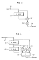
- FIG. 3 One concrete example of the vertical direction LPF 10 shown in Fig. 1 is shown in block from in Fig. 3.
- 31 is a 1 H (one-horizontal-line) delay circuit; 32 is an adder; 33 is a 1/2 multiplier; 34 is an input terminal; and 35 is an output terminal.
- the arrangement shown in Fig. 3 is a well known digital filter which serves as a vertical direction LPF. The operation thereof will be explained below.
- the interframe difference signal which is an output from the substracter 2 of Fig. 1 is supplied to the input terminal 34 via the horizontal direction LPF 3.
- the interframe difference signal thus supplied to one terminal of the adder 32 as well as the 1 H delay circuit 31.
- the output from the 1 H delay circuit 31 is supplied to the other terminal of the adder 32.
- the interframe difference signal and the output from the 1 H delay circuit 31 are added in the adder 32.
- the output from the adder 32 is 1/2-multiplied by the 1/2 multiplier 33.
- the output from the 1/2 multiplier 33 is derived from the output terminal 35 as a interframe difference signal with the vertical direction aliased portion removed.
- FIG. 4 Another example of the vertical direction LPF 10 shown in Fig. 1 is shown in block form in Fig. 4.
- 41 and 42 are a 1 H delay circuit, respectively, 43 and 45 are a 1/4 multiplier, respectively; 44 is a 1/2 multiplier; 46 is a summing circuit; 47 is an input terminal and 48 is an output terminal.
- the arrangement shown in Fig. 4 is also a well known digital filter which serves as a vertical direction LPF. The operation thereof will be explained below.
- the interframe difference signal is supplied to the input terminal 47.
- the interframe difference signal thus supplied is supplied to the 1 H delay circuit 41 and the 1/4 multiplier 43.
- the output from the 1 H delay circuit 41 is 1 H delay circuit 42 and the 1/2 multiplier 44.
- the output from the 1 H delay circuit 42 is supplied to the 1/4 multiplier 45.
- the respective outputs from the 1/2 multiplier 44 and the 1/4 multipliers 43 and 45 are supplied to the summing circuit 46 and summed there.
- the output (summed result) from the summing circuit 46 is derived through the output terminal 48 as a interframe difference signal with the vertical direction aliased portion filtered and removed.
Landscapes
- Engineering & Computer Science (AREA)
- Multimedia (AREA)
- Signal Processing (AREA)
- Television Systems (AREA)
- Compression Or Coding Systems Of Tv Signals (AREA)
- Processing Of Color Television Signals (AREA)
- Color Television Systems (AREA)
Applications Claiming Priority (2)
| Application Number | Priority Date | Filing Date | Title |
|---|---|---|---|
| JP62247790A JPH0191586A (ja) | 1987-10-02 | 1987-10-02 | 動き検出回路 |
| JP247790/87 | 1987-10-02 |
Publications (3)
| Publication Number | Publication Date |
|---|---|
| EP0310032A2 true EP0310032A2 (fr) | 1989-04-05 |
| EP0310032A3 EP0310032A3 (en) | 1990-07-25 |
| EP0310032B1 EP0310032B1 (fr) | 1993-12-01 |
Family
ID=17168686
Family Applications (1)
| Application Number | Title | Priority Date | Filing Date |
|---|---|---|---|
| EP19880115996 Expired - Lifetime EP0310032B1 (fr) | 1987-10-02 | 1988-09-28 | Circuit de détection de mouvement |
Country Status (7)
| Country | Link |
|---|---|
| US (1) | US4884136A (fr) |
| EP (1) | EP0310032B1 (fr) |
| JP (1) | JPH0191586A (fr) |
| KR (1) | KR910009881B1 (fr) |
| CN (1) | CN1011465B (fr) |
| CA (1) | CA1289657C (fr) |
| DE (1) | DE3885994T2 (fr) |
Cited By (7)
| Publication number | Priority date | Publication date | Assignee | Title |
|---|---|---|---|---|
| EP0488723A3 (en) * | 1990-11-30 | 1992-07-29 | Canon Kabushiki Kaisha | Movement vector detection apparatus |
| EP0529761A3 (en) * | 1991-08-30 | 1993-07-14 | Matsushita Electric Industrial Co., Ltd | Method and apparatus for motion aperture correction |
| EP0556501A1 (fr) * | 1992-01-22 | 1993-08-25 | Samsung Electronics Co., Ltd. | Détecteur de mouvement vidéo |
| EP0540347A3 (en) * | 1991-10-30 | 1994-06-08 | Mitsubishi Electric Corp | Motion detection circuit for high definition television picture signal based on the muse system |
| EP0991017A3 (fr) * | 1998-09-29 | 2000-10-25 | Matsushita Electric Industrial Co., Ltd. | Circuit de dètection de mouvement et circuit de suppression de bruit le comprenant |
| EP0991016A3 (fr) * | 1998-09-29 | 2000-10-25 | Matsushita Electric Industrial Co., Ltd. | Circuit de détection de mouvement et circuit de suppression de bruit le comprenant |
| EP1063849A1 (fr) * | 1999-06-21 | 2000-12-27 | Matsushita Electric Industrial Co., Ltd. | Circuit de détection de mouvement et circuit de suppression de bruit le comprenant |
Families Citing this family (25)
| Publication number | Priority date | Publication date | Assignee | Title |
|---|---|---|---|---|
| US5111511A (en) * | 1988-06-24 | 1992-05-05 | Matsushita Electric Industrial Co., Ltd. | Image motion vector detecting apparatus |
| US5109425A (en) * | 1988-09-30 | 1992-04-28 | The United States Of America As Represented By The United States National Aeronautics And Space Administration | Method and apparatus for predicting the direction of movement in machine vision |
| US4953032A (en) * | 1988-11-30 | 1990-08-28 | Hitachi, Ltd. | Motion signal generating circuit for use in a television receiver |
| JP2576612B2 (ja) * | 1988-12-28 | 1997-01-29 | 日本ビクター株式会社 | 信号変換装置 |
| US5134472A (en) * | 1989-02-08 | 1992-07-28 | Kabushiki Kaisha Toshiba | Moving object detection apparatus and method |
| JPH0418887A (ja) * | 1990-04-20 | 1992-01-23 | Sony Corp | 静止画伝送方式 |
| US6104863A (en) | 1990-08-17 | 2000-08-15 | Samsung Electronics Co., Ltd. | Video signal encoded with additional detail information |
| JPH04207481A (ja) * | 1990-11-30 | 1992-07-29 | Canon Inc | 動き検出装置 |
| US5581309A (en) * | 1992-02-03 | 1996-12-03 | Sanyo Electric Co., Ltd. | Motion vector detecting circuit |
| KR950002658B1 (ko) * | 1992-04-11 | 1995-03-24 | 주식회사금성사 | 영상신호의 압축 부호화 및 복호화장치 |
| US5311305A (en) * | 1992-06-30 | 1994-05-10 | At&T Bell Laboratories | Technique for edge/corner detection/tracking in image frames |
| KR0151410B1 (ko) * | 1992-07-03 | 1998-10-15 | 강진구 | 영상신호의 운동벡터 검출방법 |
| EP0622960A3 (fr) * | 1993-04-30 | 1996-06-12 | Matsushita Electric Industrial Co Ltd | Circuit de détection de mouvement. |
| JPH06351002A (ja) * | 1993-06-08 | 1994-12-22 | Matsushita Electric Ind Co Ltd | 動き信号検出方法およびこれを用いた映像信号処理装置 |
| US5509089A (en) * | 1993-09-09 | 1996-04-16 | Intel Corporation | Method and system for encoding images using temporal filtering |
| EP0679032B1 (fr) * | 1994-04-20 | 2010-06-23 | Oki Electric Industry Co., Ltd. | Méthode et appareil de codage et de décodage d'images utilisant une synthèse de contours et une transformation en ondelettes inverse |
| JP3500751B2 (ja) * | 1995-01-20 | 2004-02-23 | ソニー株式会社 | 画像信号処理装置及び撮像装置 |
| KR0163922B1 (ko) * | 1995-09-19 | 1999-01-15 | 김광호 | 카메라 영상의 움직임 벡터 검출장치 및 그 검출방법 |
| CN1606758A (zh) | 2000-08-31 | 2005-04-13 | 雷泰克公司 | 传感器和成像系统 |
| TW569631B (en) * | 2001-05-28 | 2004-01-01 | Matsushita Electric Industrial Co Ltd | Image-actions detection-circuit |
| DE10302003B4 (de) * | 2002-02-26 | 2011-06-16 | Thomson Licensing S.A. | Verfahren und Schaltung zur Bestimmung des Rauschanteils in einem Videosignal |
| US7321699B2 (en) | 2002-09-06 | 2008-01-22 | Rytec Corporation | Signal intensity range transformation apparatus and method |
| JP4891103B2 (ja) | 2007-01-25 | 2012-03-07 | キヤノン株式会社 | 動き量検出装置及びそれを利用した画像処理装置、並びにそれらの制御方法 |
| US8224033B2 (en) * | 2008-06-24 | 2012-07-17 | Mediatek Inc. | Movement detector and movement detection method |
| WO2012157542A1 (fr) * | 2011-05-13 | 2012-11-22 | 住友金属工業株式会社 | Matériau de soudage et raccord soudé |
Family Cites Families (3)
| Publication number | Priority date | Publication date | Assignee | Title |
|---|---|---|---|---|
| US4692801A (en) * | 1985-05-20 | 1987-09-08 | Nippon Hoso Kyokai | Bandwidth compressed transmission system |
| JPH0750927B2 (ja) * | 1985-11-29 | 1995-05-31 | キヤノン株式会社 | 画像信号変換装置 |
| JPS6386990A (ja) * | 1986-09-30 | 1988-04-18 | Nippon Hoso Kyokai <Nhk> | 動き検出方法 |
-
1987
- 1987-10-02 JP JP62247790A patent/JPH0191586A/ja active Granted
-
1988
- 1988-09-28 DE DE88115996T patent/DE3885994T2/de not_active Expired - Fee Related
- 1988-09-28 US US07/250,160 patent/US4884136A/en not_active Expired - Lifetime
- 1988-09-28 KR KR1019880012509A patent/KR910009881B1/ko not_active Expired
- 1988-09-28 EP EP19880115996 patent/EP0310032B1/fr not_active Expired - Lifetime
- 1988-09-29 CA CA 578895 patent/CA1289657C/fr not_active Expired - Lifetime
- 1988-09-30 CN CN88107490A patent/CN1011465B/zh not_active Expired
Cited By (11)
| Publication number | Priority date | Publication date | Assignee | Title |
|---|---|---|---|---|
| EP0488723A3 (en) * | 1990-11-30 | 1992-07-29 | Canon Kabushiki Kaisha | Movement vector detection apparatus |
| EP0529761A3 (en) * | 1991-08-30 | 1993-07-14 | Matsushita Electric Industrial Co., Ltd | Method and apparatus for motion aperture correction |
| EP0540347A3 (en) * | 1991-10-30 | 1994-06-08 | Mitsubishi Electric Corp | Motion detection circuit for high definition television picture signal based on the muse system |
| US5497203A (en) * | 1991-10-30 | 1996-03-05 | Mitsubishi Denki Kabushiki Kaisha | Motion detection circuit for high definition television based on muse |
| EP0556501A1 (fr) * | 1992-01-22 | 1993-08-25 | Samsung Electronics Co., Ltd. | Détecteur de mouvement vidéo |
| EP0991017A3 (fr) * | 1998-09-29 | 2000-10-25 | Matsushita Electric Industrial Co., Ltd. | Circuit de dètection de mouvement et circuit de suppression de bruit le comprenant |
| EP0991016A3 (fr) * | 1998-09-29 | 2000-10-25 | Matsushita Electric Industrial Co., Ltd. | Circuit de détection de mouvement et circuit de suppression de bruit le comprenant |
| US6567468B1 (en) | 1998-09-29 | 2003-05-20 | Matsushita Electric Industrial Co., Ltd. | Motion detection circuit and a noise suppressing circuit including the same |
| US6687300B1 (en) | 1998-09-29 | 2004-02-03 | Matsushita Electic Industrial Co., Inc. | Motion detection circuit and a noise suppressing circuit including the same |
| EP1063849A1 (fr) * | 1999-06-21 | 2000-12-27 | Matsushita Electric Industrial Co., Ltd. | Circuit de détection de mouvement et circuit de suppression de bruit le comprenant |
| US6459734B1 (en) | 1999-06-21 | 2002-10-01 | Matsushita Electric Industrial Co., Ltd. | Motion detection circuit and a noise suppression circuit including the same |
Also Published As
| Publication number | Publication date |
|---|---|
| JPH0530112B2 (fr) | 1993-05-07 |
| DE3885994T2 (de) | 1994-04-28 |
| CA1289657C (fr) | 1991-09-24 |
| KR910009881B1 (ko) | 1991-12-03 |
| CN1011465B (zh) | 1991-01-30 |
| EP0310032A3 (en) | 1990-07-25 |
| EP0310032B1 (fr) | 1993-12-01 |
| US4884136A (en) | 1989-11-28 |
| CN1032475A (zh) | 1989-04-19 |
| KR890007586A (ko) | 1989-06-20 |
| JPH0191586A (ja) | 1989-04-11 |
| DE3885994D1 (de) | 1994-01-13 |
Similar Documents
| Publication | Publication Date | Title |
|---|---|---|
| EP0310032B1 (fr) | Circuit de détection de mouvement | |
| US4237484A (en) | Technique for transmitting digital data together with a video signal | |
| EP0216928A1 (fr) | Procede et appareil de compression de donnees video | |
| CA2204722A1 (fr) | Circuit de commande automatique de gain destine a un recepteur numerique | |
| EP0741472A3 (fr) | Méthode et circuit pour le traitement d'un signal à débit de symbole variable | |
| GB2162018A (en) | Moving picture frame rate conversion system | |
| US4639767A (en) | Apparatus for detecting movement in a television signal based on taking ratio of signal representing frame difference to signal representing sum of picture element differences | |
| US5602591A (en) | System for generating a weighting coefficient using inter-frame difference signals at a center pixel for detecting motion information and at pixels surrounding the center pixel and quantizing the difference signal at the center pixel | |
| US4907269A (en) | Process and circuit layout for the recognition of an identification sign (signum) contained in a video signal | |
| EP1174721B1 (fr) | Appareil détecteur de la gigue de phase et boucle à verrouillage de phase utilisant la gigue de phase détectée | |
| US4223270A (en) | Multiplexed CCD pulse width discriminator | |
| EP0400730B1 (fr) | Dispositif détecteur de passages par zéro | |
| US5043800A (en) | Method and apparatus for keying a digital video signal | |
| KR830009851A (ko) | 겸용식, 트랜스코더블 및 계층식 디지탈 텔레비젼 시스템 | |
| WO1991004552A1 (fr) | Dispositif de compression d'informations | |
| KR100337723B1 (ko) | 화상데이터의확대율또는축소율을검출하기위한장치및방법 | |
| KR100434632B1 (ko) | 휘도 신호 처리 장치 | |
| EP0153034B1 (fr) | Filtre de séparation signal de luminance-signal de couleur | |
| KR910007351A (ko) | 고스트 제거장치 및 방법 | |
| US4843467A (en) | Method and apparatus for improving the picture quality in multi-dimensional differential pulse code modulation | |
| EP0663767A1 (fr) | Procédé de détection et de correction d'aliasing utilisé dans le traitement de signaux vidéo | |
| JPS634781A (ja) | デジタルテレビジヨン受像機における動き信号検出回路 | |
| JPH03295485A (ja) | レーダ信号の圧縮方式 | |
| SU1406820A1 (ru) | Устройство интерпол ции цифрового телевизионного сигнала | |
| JPH0740742B2 (ja) | テレビジヨン信号の動き検出回路 |
Legal Events
| Date | Code | Title | Description |
|---|---|---|---|
| PUAI | Public reference made under article 153(3) epc to a published international application that has entered the european phase |
Free format text: ORIGINAL CODE: 0009012 |
|
| AK | Designated contracting states |
Kind code of ref document: A2 Designated state(s): DE FR GB NL |
|
| PUAL | Search report despatched |
Free format text: ORIGINAL CODE: 0009013 |
|
| AK | Designated contracting states |
Kind code of ref document: A3 Designated state(s): DE FR GB NL |
|
| 17P | Request for examination filed |
Effective date: 19901012 |
|
| 17Q | First examination report despatched |
Effective date: 19921124 |
|
| GRAA | (expected) grant |
Free format text: ORIGINAL CODE: 0009210 |
|
| AK | Designated contracting states |
Kind code of ref document: B1 Designated state(s): DE FR GB NL |
|
| ET | Fr: translation filed | ||
| REF | Corresponds to: |
Ref document number: 3885994 Country of ref document: DE Date of ref document: 19940113 |
|
| REG | Reference to a national code |
Ref country code: GB Ref legal event code: 746 Effective date: 19940322 |
|
| PLBE | No opposition filed within time limit |
Free format text: ORIGINAL CODE: 0009261 |
|
| STAA | Information on the status of an ep patent application or granted ep patent |
Free format text: STATUS: NO OPPOSITION FILED WITHIN TIME LIMIT |
|
| 26N | No opposition filed | ||
| REG | Reference to a national code |
Ref country code: GB Ref legal event code: 747D |
|
| REG | Reference to a national code |
Ref country code: GB Ref legal event code: 747C |
|
| PGFP | Annual fee paid to national office [announced via postgrant information from national office to epo] |
Ref country code: FR Payment date: 20000912 Year of fee payment: 13 |
|
| PGFP | Annual fee paid to national office [announced via postgrant information from national office to epo] |
Ref country code: DE Payment date: 20000918 Year of fee payment: 13 |
|
| PGFP | Annual fee paid to national office [announced via postgrant information from national office to epo] |
Ref country code: GB Payment date: 20000927 Year of fee payment: 13 |
|
| PGFP | Annual fee paid to national office [announced via postgrant information from national office to epo] |
Ref country code: NL Payment date: 20000928 Year of fee payment: 13 |
|
| PG25 | Lapsed in a contracting state [announced via postgrant information from national office to epo] |
Ref country code: GB Free format text: LAPSE BECAUSE OF NON-PAYMENT OF DUE FEES Effective date: 20010928 |
|
| REG | Reference to a national code |
Ref country code: GB Ref legal event code: IF02 |
|
| PG25 | Lapsed in a contracting state [announced via postgrant information from national office to epo] |
Ref country code: NL Free format text: LAPSE BECAUSE OF NON-PAYMENT OF DUE FEES Effective date: 20020401 |
|
| PG25 | Lapsed in a contracting state [announced via postgrant information from national office to epo] |
Ref country code: DE Free format text: LAPSE BECAUSE OF NON-PAYMENT OF DUE FEES Effective date: 20020501 |
|
| GBPC | Gb: european patent ceased through non-payment of renewal fee |
Effective date: 20010928 |
|
| PG25 | Lapsed in a contracting state [announced via postgrant information from national office to epo] |
Ref country code: FR Free format text: LAPSE BECAUSE OF NON-PAYMENT OF DUE FEES Effective date: 20020531 |
|
| NLV4 | Nl: lapsed or anulled due to non-payment of the annual fee |
Effective date: 20020401 |
|
| REG | Reference to a national code |
Ref country code: FR Ref legal event code: ST |
|
| NLV4 | Nl: lapsed or anulled due to non-payment of the annual fee |
Effective date: 20020401 |