EP0310046B1 - Verfahren und System zum Ermitteln der Signale eines Videoprogrammierungssystems - Google Patents
Verfahren und System zum Ermitteln der Signale eines Videoprogrammierungssystems Download PDFInfo
- Publication number
- EP0310046B1 EP0310046B1 EP88116030A EP88116030A EP0310046B1 EP 0310046 B1 EP0310046 B1 EP 0310046B1 EP 88116030 A EP88116030 A EP 88116030A EP 88116030 A EP88116030 A EP 88116030A EP 0310046 B1 EP0310046 B1 EP 0310046B1
- Authority
- EP
- European Patent Office
- Prior art keywords
- data
- signal
- vps
- video program
- program system
- Prior art date
- Legal status (The legal status is an assumption and is not a legal conclusion. Google has not performed a legal analysis and makes no representation as to the accuracy of the status listed.)
- Expired - Lifetime
Links
- 238000000034 method Methods 0.000 title claims description 21
- 239000000872 buffer Substances 0.000 claims description 74
- 230000015654 memory Effects 0.000 claims description 47
- 238000010586 diagram Methods 0.000 description 3
- 230000000052 comparative effect Effects 0.000 description 2
- 230000002159 abnormal effect Effects 0.000 description 1
- 238000012986 modification Methods 0.000 description 1
- 230000004048 modification Effects 0.000 description 1
Images





Classifications
-
- H—ELECTRICITY
- H04—ELECTRIC COMMUNICATION TECHNIQUE
- H04N—PICTORIAL COMMUNICATION, e.g. TELEVISION
- H04N7/00—Television systems
- H04N7/08—Systems for the simultaneous or sequential transmission of more than one television signal, e.g. additional information signals, the signals occupying wholly or partially the same frequency band, e.g. by time division
- H04N7/087—Systems for the simultaneous or sequential transmission of more than one television signal, e.g. additional information signals, the signals occupying wholly or partially the same frequency band, e.g. by time division with signal insertion during the vertical blanking interval only
- H04N7/088—Systems for the simultaneous or sequential transmission of more than one television signal, e.g. additional information signals, the signals occupying wholly or partially the same frequency band, e.g. by time division with signal insertion during the vertical blanking interval only the inserted signal being digital
- H04N7/0887—Systems for the simultaneous or sequential transmission of more than one television signal, e.g. additional information signals, the signals occupying wholly or partially the same frequency band, e.g. by time division with signal insertion during the vertical blanking interval only the inserted signal being digital for the transmission of programme or channel identifying signals
Definitions
- the present invention relates to a method and system for determining video program system (VPS) signals detected from television signals.
- VPN video program system
- VPS signal is represented by 1-15 word data
- word data word numbers 11-14
- the word data in current use includes the broadcasting data (the month, day and hour), the nationality code of a broadcasting station, a program source code, etc, which are previously published in a television program guide and assigned to each of programs.
- a TV is turned on and a video tape recorder (VTR) is controlled in a recording mode.
- VTR video tape recorder
- this receiving equipment decodes a received VPS signal and determines whether or not a program source code obtained by the decoding corresponds to a preset program source code. Therefore, it is necessary for the receiving equipment to accurately detect the VPS signal. However, by mixed with noise, the VPS signal may become difficult to detect.
- a example of a determination circuit for VPS signals is shown in DE-A-35 11 737.
- the determination circuit includes a memory, a comparing circuit, and a counter.
- a detected VPS signal is stored in the memory, compared with a next detected VPS signal.
- the counter is incremented by one.
- the counter resets the determination circuit only if its count is not higher than p2. If the count is p3 or higher, the program counter completes the count sequence and resets the determination circuit not until count p11. By the above process, a count value of the counter is obtained when the same VPS signal is successively detected.
- the determination circuit determines that the VPS signals correspond to a program being broadcast.
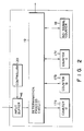
- the another sample of a known determination circuit for VPS circuit determines by using the majority of VPS signals, and includes input buffer 16, counters 17a, 17b and 17c, no-signal counter 18, determination process circuit 19 and controller 20.
- Controller 20 is constructed of a central processing unit (CPU) and the like and controls the timing of access to input buffer 16. The determination of VPS signals is performed in accordance with a flowchart as shown in Fig. 3.
- a VPS signal is detected from a television signal and input into input buffer 16 at a specified timing by a control signal output from controller 20 (step S1).
- the VPS signal input into input buffer 16 is regarded as a VPS signal for a program A
- counter 17a is incremented by one (step S5).
- Determination process circuit 19 determines whether or not a next VPS signal input into input buffer 16 coincides with the VPS signal for the program A (step S2). In step S2, when the next VPS signal corresponds to the program A, counter 17a is incremented by one (Step S5).
- step S2 if the next VPS signal does not correspond to the program A, the next VPS signal is regarded as a VPS signal for a program B, counter 17b is incremented by one (step S6).
- determination process circuit 19 determines whether or not a new VPS signal input into input buffer 16 coincides with the VPS signal for programs A or B (step 2, step S3). When the new VPS signal corresponds to the program A, counter 17a is incremented by one (step S5). When the new VPS signal corresponds to the program B, counter 17b is incremented by one (step S6).
- step S7 If the new VPS signal does not correspond to the programs A and B, the new VPS signal is regarded as a VPS signal for a program C, counter 17c is incremented by one (step S7).
- step S7 When a VPS signal input into input buffer 16 corresponds to the program C (step S4), step S7 is perfomed.
- no-signal counter 18 is incremented by one (step S8).
- step S9 The above process is performed at regular intervals and continued for a predetermined period.
- step S10 is then performed.
- step S10 the VPS signal is detected which corresponds to a counter having a maximum count value among counters 17a, 17b and 17c and no-signal counter 18. For example, when the count value of counter 17a is maximum, the VPS signal for program A has been detected most frequently during the predetermined period. As a result, the conventional determination circuit determines that a program being broadcast is A.
- VPS signals when television signals are received unstably, VPS signals will also become unstable and thus may not be determined. In such a case, the determination procedure as shown in Fig. 3 will fail to determine any of VPS signals corresponding to programs in each of steps S2, S3 and S4, increasing the count value of no-signal counter 18. For example, if normal VPS signals are detected only two times during five determination processes, the no-signal counter 18 will count three times. Thus, determination circuit would be determined that the VPS signal is not superimposed upon a television signal being received.
- an apparatus which is capable of accurately detecting and determining VPS signals from received television signals.
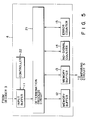
- a television signal received by receiving circuit 1 through antenna 1a is applied to detecting circuit 2, VTR 9 and TV 10.
- Detecting circuit 2 detects a VPS signal from the television signal and outputs the VPS signal to a decoder 3.
- the VPS signal decoded in decoder 3 is applied to determination circuit 4.
- Determination circuit 4 determines whether or not the decoded VPS signal is a VPS signal to be used to control VTR 9 and TV 10.
- a program code is input by program code input unit 8 and then stored in memory 7.
- determination circuit 4 determines that the VPS signal is to be used for controlling VTR 9 and TV 10
- a program code corresponding to the VPS signal is compared with the program code read out from memory 7 by comparing circuit 5.
- Control circuit 6 is formed of a microprocessor and the like and produces a control signal to operate VTR 9 and TV 10 in accordance with the comparative result output from comparing circuit 5.
- VTR 9 and TV 10 respond to the control signal so that the former operates in the recording mode and the latter turns on, for example.
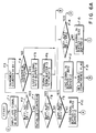
- determination circuit 4 comprises input buffer 11, memory buffers 12 and 13, no-signal counter 14, error counter 15, determination process circuit 21 and controller 22. Determination circuit 4 performs the determination of VPS signals in accordance with such flowcharts as shown in Figs. 6A and 6B and Fig. 7.
- a VPS signal is detected from a television signal and then input into input buffer 11 (step F1).
- step F2 determination process circuit 21 determines whether the VPS signal input into input buffer 11 is a no-signal or not.
- no-signal counter 14 is incremented by one (step F3).
- No-signal counter 14 is designed to overflow when over n no-signals are successively input, that is, when no-signal counter 14 are counted over n times.
- step F4 the status of no-signal counter 14 is determined.
- the no-signal counter 14 overflows, the no-signal is loaded into memory buffer 13 (step F5).
- the no-signal stored in memory buffer 13 is used as a VPS signal for controlling VTR 9 and TV 10 and thus output to comparing circuit 5 (step F6).
- step F7 When the VPS signal input into input buffer 11 is a normal signal, no-signal counter 14 is initialized (step F7) and a comparison is made between the VPS signal stored in input buffer 11 and the VPS signal stored in memory buffer 13 (step F8). When no coincidence occurs between the VPS signals, another comparison is made between the VPS signal stored in input buffer 11 and the VPS signal stored in memory buffer 12 (step F9). When no coincidence occurs between the VPS signals in step F9, the VPS signal stored in input buffer 11 is regarded as a new input signal and loaded into memory buffer 12 (step F10).
- step F29 If a twice-coincidence flag representing that two normal VPS signals of the same type are successively input and a triple-coincidence flag representing that three normal VPS signals of the same type are successively input have both been set in determination process circuit 21, these flags are reset in step F29. Further, error counter 15 is incremented by one (step F11).
- step F9 when a coincidence occurs between the VPS signal stored in input buffer 11 and the VPS signal stored in memory buffer 12, the VPS signal in input buffer 11 is loaded into memory buffer 13 (step F12), and the twice-coincidence flag is set (step F13).
- step F8 when a coincidence occurs between the VPS signal in input buffer 11 and the VPS signal in memory buffer 13, the VPS signal in input buffer 11 is compared with the VPS signal in memory buffer 12 (step F14). When no coincidence occurs between the VPS signals, the VPS signal in input buffer 11 is loaded into memory buffer 12 (step F15). The twice-coincidence flag is reset in step F16, and error counter 15 is incremented by one in step F11.
- determination process circuit 21 determines whether or not the twice-coincidence flag is set in step F17. If the flag has already been set, it is determined that the same normal VPS signals have been input successively three times, or a triple-coincidence has occurred. Thus the triple-coincidence flag is set in step F18.
- the VPS signal in memory buffer 13 is output to comparing circuit 5 as the VPS signal adapted for controlling VTR 9 and TV 10 (step F19) . Error counter 15 is initialized (step F20), and the twice-coincidence flag is reset (step F21) .
- step F22 determination process circuit 21 determines whether or not the triple-coincidence flag is set. If the triple-coincidence flag is set in step F22, the operations of steps F18 through F21 are carried out. If no triple-coincidence flag is set, then the twice-coincidence flag is set (step F23).
- error counter 15 When various kinds of normal VPS signals are input into input buffer 11, error counter 15 is incremented by one each time the VPS signal changes in kind (step F11). If error counter 15 exceeds a predetermined count, i.e., overflows in step F24, then a determination of occurrence of an abnormal input state is made so that a no-signal is loaded into memory buffer 13 (step F25). The VPS signal in memory buffer 13 is output to comparing circuit 5 as a VPS signal used for controlling VTR 9 and TV 10 (step F26). Moreover, error counter 15 is initialized (step F27).
- step F28 The above operations are performed at regular intervals and continued for a predetermined period.
- a VPS signal is detected from a television signal and input into input buffer 11 (step A1).
- determination process circuit 21 determines whether or not the VPS signal input into input buffer 11 is a no-signal.
- no-signal counter 14 is incremented by one (step A3).
- No-signal counter 14 is designed to overflow when over n no-signals are successively input into input buffer 11.
- step A4 When no-signal counter 14 overflows (step A4), the no-signal is loaded into memory buffer 13 (step A5) and then the no-signal stored in memory buffer 13 is output to comparing circuit 5 as a VPS signal used for controlling VTR 9 and TV 10 (step A6).
- step A7 When the VPS signal input into input buffer 11 is a normal VPS signal, no-signal counter 14 is initialized (step A7), and the VPS signal in input buffer 11 is compared with the VPS signal in memory buffer 12 (step A8).
- step A8 the VPS signal in input buffer 11 and the VPS signal in memory buffer 12 coincide with each other, a comparison is made between the VPS signal input buffer 11 and the VPS signal in memory buffer 13 (step A9). If a coincidence occurs between the VPS signal in input buffer 11 and the VPS signal in memory buffer 13 in step A9, then it is determined that the same normal VPS signals have successively been input three times.
- the VPS signal in memory buffer 13 is output to comparing circuit 5 as a VPS signal used for controlling VTR 9 and TV 10 (step A13).
- error counter 15 is initialized (step A12).
- step A9 If no coincidence occurs between the VPS signal in input buffer 11 and the VPS signal in memory buffer 13 in step A9, then the VPS signal in memory buffer 12 is loaded into memory buffer 13 (step A13), and the VPS signal in input buffer 11 is loaded into memory buffer 12 (step A14).
- step A8 If no coincidence occurs between the VPS signal in input buffer 11 and the VPS signal in memory buffer 12 in step A8, then the VPS signal in memory buffer 12 is loaded into memory buffer 13 (step A15), and the VPS signal in input buffer 11 is loaded into memory buffer 12 (step A16). Further, error counter 15 is incremented by one (step A17).
- step A18 when error counter 15 exceeds a predetermined count, i.e., error counter 15 overflows, the no-signal is loaded into memory buffer 13 (step A19), and the VPS signal in memory buffer 13 is output to comparing circuit 5 (step A20). Further, error counter 15 is initialized (step A21).
- step A22 The above operations are performed at regular intervals and continued for a predetermined period.
- VPS signals used for controlling a VTR and a TV are regarded as no-signals.
- Fig. 8B when three signals (program A) are input in succession (including the case where under n no-signals are successively input between the signals (program A), the signals are regarded as VPS signals used for controlling VTR and TV.
- Fig. 8C when a signal for program B is input between signals (program A), the continuity of signals (program A) will be lost.
- the signals (program A) are regarded as the VPS signals used for controlling VTR and TV.
- the present invention may be applied to the determination of four or five VPS signals which are successively input. In this case, three or four memory buffers will be needed.
Landscapes
- Engineering & Computer Science (AREA)
- Multimedia (AREA)
- Signal Processing (AREA)
- Testing, Inspecting, Measuring Of Stereoscopic Televisions And Televisions (AREA)
- Television Signal Processing For Recording (AREA)
Claims (2)
- Verfahren zum Verifizieren bzw. Bestätigen von Daten, die in einem Videoprogrammierungssystemsignal enthalten sind, das aus einem Fernsehsignal erkannt wird, mit den Schritten zum:(a) Verriegeln bzw. Zwischenspeichern von ersten Daten in einer Eingabepuffereinrichtung (11), wobei die ersten Daten aus dem Fernsehsignal während eines ersten Zeitintervalls erhalten werden, das entweder ein Videoprogrammierungssystemsignal, das Videoprogrammierungssysteminformationen umfaßt, oder ein Kein-Signal, das keine Informationen umfaßt, enthält;(b) Ermitteln, ob die ersten Daten ein Kein-Signal sind;(c) Erhöhen eines ersten Zählers (14) und Fortfahren mit Schritt (h), jedesmal, wenn die ersten Daten ein Kein-Signal sind;(d) aufeinanderfolgenden Vergleichen der ersten Daten mit allen von einer Vielzahl von zweiten Daten, die in einer Vielzahl von Speichern (12, 13) der Speicherpuffereinrichtung gespeichert sind, um Datenidentität/-unterschied zu ermitteln, wobei die Vielzahl der zweiten Daten aus Videoprogrammierungssystemsignalen erhalten werden, die während einer Vielzahl von Zeitsignalen vor dem ersten Zeitsignal empfangen werden;(e) Speichern von Identitätsdaten in einer Datenermittlungsspeichereinrichtung (21), wenn Datenidentität von der Vergleichseinrichtung (21) ermittelt wird, wodurch angezeigt wird, daß Videoprogrammierungssystemsignale, die dieselben Daten haben, seriell eingegeben werden, und Löschen der gespeicherten Identitätsdaten, wenn ein Datenunterschied von der Vergleichseinrichtung (21) ermittelt wird;(f) Speichern der ersten Daten in mindestens einem von jenen der Vielzahl von Speichern (12, 13), die Daten enthalten, die sich von den ersten Daten unterscheiden, wenn ein Datenunterschied erkannt wird;(g) Hochzählen eines Fehlerzählers (15), jedesmal, wenn ein Datenunterschied ermittelt wird;(h) Ausgeben von dritten Daten die eine Abwesenheit von Daten in den Videoprogrammierungssystemsignalen anzeigen, jedesmal, wenn ein Zählwert des ersten Zählers (14) einen ersten Wert überschreitet oder ein Zählwert des Fehlerzählers (15) einen zweiten Wert überschreitet, und Ausgeben der ersten Daten, wenn die Datenermittlungsspeichereinrichtung (21) die Identitätsdaten enthält, die anzeigen, daß eine vorbestimmte Anzahl von Videoprogrammierungssystemsignale, die dieselben Daten haben, seriell eingegeben werden.
- System zum Verifizieren von Daten, die in einem Videoprogrammierungssystemsignal enthalten sind, das aus einem Fernsehsignal erkannt wird, mit:
einer Eingabepuffereinrichtung (11) zum Speichern von ersten Daten, wobei die ersten Daten aus dem Fernsehsignal während eines ersten Zeitintervalls erhalten werden, das entweder ein Videoprogrammierungssystemsignal, das Videoprogrammierungssysteminformationen umfaßt, oder ein Kein-Signal, das keine Informationen umfaßt, enthält;
einer Speicherpuffereinrichtung, die eine Vielzahl von Speichern (12, 13) zum Speichern einer Vielzahl von zweiten Daten umfaßt, wobei die Vielzahl von zweiten Daten aus Videoprogrammierungssystemsignalen erhalten werden, die während einer Vielzahl von Zeitintervallen vor dem ersten Zeitintervall empfangen werden;
einer Ermittlungseinrichtung (21) zum Ermitteln, ob das erste Signal ein Kein-Signal ist;
einer ersten Zählereinrichtung (14) zum Hochzählen, jedesmal, wenn die Ermittlungseinrichtung (21) ermittelt, daß die ersten Daten ein Kein-Signal sind;
einer Vergleichseinrichtung (21) zum aufeinanderfolgenden Vergleichen der ersten Daten mit allen der Vielzahl von zweiten Daten, die in der Vielzahl von Speichern (12, 13) der Speicherpuffereinrichtung gespeichert sind, um Datenidentität/-unterschied zu ermitteln;
einer Datenermittlungsspeichereinrichtung (21) zum Speichern von Identitätsdaten, wenn Datenidentität durch die Vergleichseinrichtung (21) ermittelt wird, wodurch angezeigt wird, daß Videoprogrammierungssystemsignale, die dieselben Daten haben, seriell eingegeben werden, und zum Löschen der gespeicherten Identitätsdaten, wenn ein Datenunterschied von der Vergleichseinrichtung (21) ermittelt wird;
einer Fehlerzählereinrichtung (15) zum Hochzählen, jedesmal, wenn die Vergleichseinrichtung (21) einen Datenunterschied ermittelt;
einer Ausgabeeinrichtung (4) zum Ausgeben von dritten Daten, die die Abwesenheit von Daten in den Videoprogrammierungssystemsignalen anzeigen, jedesmal, wenn ein Zählwert des ersten Zählers (14) einen ersten Wert überschreitet oder ein Zählwert des Fehlerzählers (15) einen zweiten Wert überschreitet, und zum Ausgeben der ersten Daten, wenn die Datenermittlungsspeichereinrichtung (21) die Identitätsdaten enthält, was anzeigt, daß eine vorbestimmte Anzahl von Videoprogrammierungssystemsignalen, die dieselben Daten haben, seriell eingegeben werden.
Applications Claiming Priority (2)
| Application Number | Priority Date | Filing Date | Title |
|---|---|---|---|
| JP246034/87 | 1987-09-30 | ||
| JP62246034A JPS6489784A (en) | 1987-09-30 | 1987-09-30 | Video program identifying signal deciding device |
Publications (3)
| Publication Number | Publication Date |
|---|---|
| EP0310046A2 EP0310046A2 (de) | 1989-04-05 |
| EP0310046A3 EP0310046A3 (de) | 1991-04-24 |
| EP0310046B1 true EP0310046B1 (de) | 1995-03-08 |
Family
ID=17142465
Family Applications (1)
| Application Number | Title | Priority Date | Filing Date |
|---|---|---|---|
| EP88116030A Expired - Lifetime EP0310046B1 (de) | 1987-09-30 | 1988-09-28 | Verfahren und System zum Ermitteln der Signale eines Videoprogrammierungssystems |
Country Status (4)
| Country | Link |
|---|---|
| US (1) | US4891703A (de) |
| EP (1) | EP0310046B1 (de) |
| JP (1) | JPS6489784A (de) |
| DE (1) | DE3853247T2 (de) |
Families Citing this family (18)
| Publication number | Priority date | Publication date | Assignee | Title |
|---|---|---|---|---|
| US4965825A (en) | 1981-11-03 | 1990-10-23 | The Personalized Mass Media Corporation | Signal processing apparatus and methods |
| USRE47642E1 (en) | 1981-11-03 | 2019-10-08 | Personalized Media Communications LLC | Signal processing apparatus and methods |
| US7831204B1 (en) | 1981-11-03 | 2010-11-09 | Personalized Media Communications, Llc | Signal processing apparatus and methods |
| US5701593A (en) * | 1989-08-25 | 1997-12-23 | Deutsche Thomson-Brandt Gmbh | Method and means for the transmitter-side controller operation of a receiver-side device |
| NL8902241A (nl) * | 1989-09-07 | 1991-04-02 | Philips Nv | Inrichting voor het programmeren van een videorecorder, en een videorecorder voorzien van de inrichting. |
| US5469207A (en) * | 1989-12-06 | 1995-11-21 | British Broadcasting Corporation | Method of labelling a broadcast signal including transmitting a sequence of program labels |
| US5003390A (en) * | 1990-03-26 | 1991-03-26 | Pbse Enterprises, Inc. | Search and lock technique for reliable acquisition of data transmitted via television signals |
| JP2830334B2 (ja) * | 1990-03-28 | 1998-12-02 | ソニー株式会社 | 素材分配システム |
| GB9012005D0 (en) * | 1990-05-30 | 1990-07-18 | British Broadcasting Corp | Broadcast receiver system |
| KR0178536B1 (ko) * | 1991-03-11 | 1999-04-15 | 강진구 | 동종 프로그램 채널 선택방법 |
| JP2606477B2 (ja) * | 1991-04-17 | 1997-05-07 | 日本ビクター株式会社 | 映像信号送受信装置 |
| US5210611A (en) * | 1991-08-12 | 1993-05-11 | Keen Y. Yee | Automatic tuning radio/TV using filtered seek |
| SG49266A1 (en) * | 1992-05-19 | 1998-05-18 | Thomson Multimedia Sa | Method and apparatus for device control by data transmission in TV lines |
| BE1007077A3 (nl) * | 1993-05-13 | 1995-03-07 | Philips Electronics Nv | Zendstation voor het uitzenden van een pluraliteit van televisie programma's, en een ontvanger voor het ontvangen van de programma's. |
| BE1007167A3 (nl) * | 1993-05-13 | 1995-04-11 | Philips Electronics Nv | Zendstation voor het uitzenden van een pluraliteit van televisie programma's, en een ontvanger voor het ontvangen daarvan. |
| EP0967801A1 (de) * | 1998-06-26 | 1999-12-29 | Deutsche Thomson-Brandt Gmbh | Verfahren und Vorrichtung zur Mehrnormenvideodatenerfassung |
| US7440677B2 (en) * | 2004-12-23 | 2008-10-21 | Ati Technologies Inc. | Detection of copy protection indicators or redistribution control indicators in an analog video signal |
| US20090251610A1 (en) * | 2008-04-08 | 2009-10-08 | Hsin-Chung Wang | Vertical blanking interval slicer and related method |
Family Cites Families (9)
| Publication number | Priority date | Publication date | Assignee | Title |
|---|---|---|---|---|
| DE3020787A1 (de) * | 1980-05-31 | 1981-12-17 | Blaupunkt-Werke Gmbh, 3200 Hildesheim | Verfahren zum uebertragen von zusaetzlichen informationen |
| DE3038088C2 (de) * | 1980-10-09 | 1982-09-09 | Institut für Rundfunktechnik GmbH, 8000 München | Datenempfänger für ein in ein Videosignal eingetastetes Datensignal |
| US4479146A (en) * | 1982-03-08 | 1984-10-23 | Discovision Associates | Vertical code verifier |
| DE3328001C2 (de) * | 1983-08-03 | 1987-05-07 | Institut für Rundfunktechnik GmbH, 8000 München | Einrichtung zum automatischen Ein- und Ausschalten des Aufzeichnungsbetriebs eines Videorecorders |
| DE3341412C1 (de) * | 1983-11-15 | 1985-05-30 | Institut für Rundfunktechnik GmbH, 8000 München | Verfahren zum Empfang periodisch wiederholter codierter Informationen, die innerhalb eines Fernsehsignals übertragen werden |
| DE3439941C1 (de) * | 1984-11-02 | 1985-08-29 | Institut für Rundfunktechnik GmbH, 8000 München | Verfahren zum Empfang periodisch wiederholter codierter Informationen, die innerhalb eines Fernsehsignals übertragen werden |
| DE3511737A1 (de) * | 1985-03-30 | 1986-10-09 | Standard Elektrik Lorenz Ag, 7000 Stuttgart | Verfahren zur ausgabe eines sendungskennungsdatenwortes zur auswertung in einem empfangsgeraet |
| US4706121B1 (en) * | 1985-07-12 | 1993-12-14 | Insight Telecast, Inc. | Tv schedule system and process |
| DE3623108C1 (en) * | 1986-07-09 | 1987-10-15 | Inst Rundfunktechnik Gmbh | Method for contribution- or time-controlled recording of television programme contributions |
-
1987
- 1987-09-30 JP JP62246034A patent/JPS6489784A/ja active Pending
-
1988
- 1988-09-22 US US07/247,604 patent/US4891703A/en not_active Expired - Fee Related
- 1988-09-28 EP EP88116030A patent/EP0310046B1/de not_active Expired - Lifetime
- 1988-09-28 DE DE3853247T patent/DE3853247T2/de not_active Expired - Fee Related
Also Published As
| Publication number | Publication date |
|---|---|
| EP0310046A2 (de) | 1989-04-05 |
| DE3853247D1 (de) | 1995-04-13 |
| JPS6489784A (en) | 1989-04-04 |
| US4891703A (en) | 1990-01-02 |
| EP0310046A3 (de) | 1991-04-24 |
| DE3853247T2 (de) | 1995-06-29 |
Similar Documents
| Publication | Publication Date | Title |
|---|---|---|
| EP0310046B1 (de) | Verfahren und System zum Ermitteln der Signale eines Videoprogrammierungssystems | |
| US4313134A (en) | Track error correction system as for video disc player | |
| US5270829A (en) | Automatically reserve-recording and reserve-playing back a broadcasted program | |
| US5237319A (en) | Remote control device with learning function | |
| CA1138537A (en) | Synchronizing signal detecting apparatus | |
| US4656604A (en) | Control circuit with recovery protection | |
| CA1303732C (en) | Apparatus for reserving programs at various recording tape running speeds | |
| US5453793A (en) | Method for recording a series program in a video cassette recorder | |
| US4159481A (en) | Synchronizing signal selecting circuit | |
| US5510849A (en) | Circuit and method for generating caption signal in video signal processing system | |
| US6401179B1 (en) | Method for storing reference information and apparatus therefor | |
| JPS59174080A (ja) | テレビジヨン信号受信装置 | |
| US3973205A (en) | Television tuning system indicator | |
| US4047227A (en) | Auxiliary signal processing circuit | |
| EP0293492B1 (de) | System zum aufzeichnen von fernsehprogrammen | |
| JPS61190755A (ja) | アドレス回路 | |
| US3980958A (en) | Signal seeking tuning system with illegal channel detection means | |
| US5619336A (en) | Recording apparatus and method for video cassette recorder having snow noise removing function | |
| US6363205B1 (en) | Method and apparatus for automatically editing programs in video tape copy system | |
| KR100200640B1 (ko) | 방송 프로그램 녹화방법 | |
| JP3279113B2 (ja) | 周波数判別方法とビデオプロジェクター | |
| KR0134242B1 (ko) | 비데오 카세트 레코더의 kbps 데이타 수신 방법 | |
| KR19990051237A (ko) | 비디오 카세트 레코더의 제어 방법 | |
| KR19980058812A (ko) | 비데오 카세트 레코더의 시간 설정 방법 | |
| KR0151169B1 (ko) | 비디오 테이프의 녹화 방지장치 |
Legal Events
| Date | Code | Title | Description |
|---|---|---|---|
| PUAI | Public reference made under article 153(3) epc to a published international application that has entered the european phase |
Free format text: ORIGINAL CODE: 0009012 |
|
| 17P | Request for examination filed |
Effective date: 19881025 |
|
| AK | Designated contracting states |
Kind code of ref document: A2 Designated state(s): DE FR GB |
|
| PUAL | Search report despatched |
Free format text: ORIGINAL CODE: 0009013 |
|
| AK | Designated contracting states |
Kind code of ref document: A3 Designated state(s): DE FR GB |
|
| 17Q | First examination report despatched |
Effective date: 19930219 |
|
| GRAA | (expected) grant |
Free format text: ORIGINAL CODE: 0009210 |
|
| AK | Designated contracting states |
Kind code of ref document: B1 Designated state(s): DE FR GB |
|
| REF | Corresponds to: |
Ref document number: 3853247 Country of ref document: DE Date of ref document: 19950413 |
|
| ET | Fr: translation filed | ||
| PLBE | No opposition filed within time limit |
Free format text: ORIGINAL CODE: 0009261 |
|
| STAA | Information on the status of an ep patent application or granted ep patent |
Free format text: STATUS: NO OPPOSITION FILED WITHIN TIME LIMIT |
|
| 26N | No opposition filed | ||
| PGFP | Annual fee paid to national office [announced via postgrant information from national office to epo] |
Ref country code: GB Payment date: 19960919 Year of fee payment: 9 |
|
| PGFP | Annual fee paid to national office [announced via postgrant information from national office to epo] |
Ref country code: DE Payment date: 19961004 Year of fee payment: 9 |
|
| PGFP | Annual fee paid to national office [announced via postgrant information from national office to epo] |
Ref country code: FR Payment date: 19970909 Year of fee payment: 10 |
|
| PG25 | Lapsed in a contracting state [announced via postgrant information from national office to epo] |
Ref country code: GB Free format text: LAPSE BECAUSE OF NON-PAYMENT OF DUE FEES Effective date: 19970928 |
|
| GBPC | Gb: european patent ceased through non-payment of renewal fee |
Effective date: 19970928 |
|
| PG25 | Lapsed in a contracting state [announced via postgrant information from national office to epo] |
Ref country code: DE Free format text: LAPSE BECAUSE OF NON-PAYMENT OF DUE FEES Effective date: 19980603 |
|
| PG25 | Lapsed in a contracting state [announced via postgrant information from national office to epo] |
Ref country code: FR Free format text: LAPSE BECAUSE OF NON-PAYMENT OF DUE FEES Effective date: 19990531 |
|
| REG | Reference to a national code |
Ref country code: FR Ref legal event code: ST |